Lennox ComfortSense L7742U Programming Manual
Touch screen
Hide thumbs
Also See for ComfortSense L7742U:
- Programming and application manual (44 pages) ,
- Owner's manual (14 pages) ,
- Homeowner's manual (15 pages)
Table of Contents
Advertisement
E2008 Lennox Industries Inc.
Dallas, Texas, USA
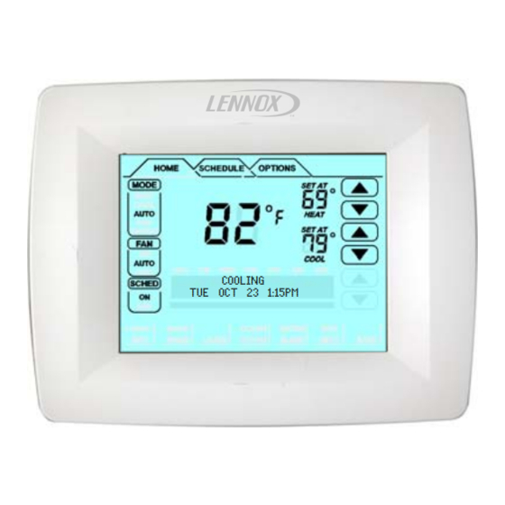
TUE OCT 23 1:15PM
IMPORTANT
Read this manual before programming this thermo-
stat.
Use this thermostat only as described in this manual.
Shipping and Packing List
1 − ComfortSenset Model L7742U touch screen, 7−day
programmable thermostat
2 − Mounting screws (M3.5x25mm self−tapping screws)
2 − Wall Anchors
1 each − Installation Quick-Start Guide, Programming &
Application Guide, Homeowner's Manual, Warranty card,
Warranty Audit tag
CAUTION
This is a 24VAC low−voltage thermostat. Do not
install on voltages higher than 30VAC.
Do not short (jumper) across terminals on the gas
valve or at the system control to test installation.
This will damage the thermostat and void the war-
ranty.
IMPORTANT
In commercial applications, the ComfortSenset
Model L7742U thermostat can only be used with ap-
proved split-system matches, and those which meet
the following installation criteria:
S installation uses 18 GAUGE thermostat wire or larger,
S thermostat wire run length DOES NOT EXCEED 300' (91m),
S load from any thermostat connection is LESS THAN 1 AMP.
If used with Harmony II
sult Application Note H−04−5.
09/08
*2P0908*
COOLING
®
Zone Control System, con-
PROGRAMMING AND
APPLICATION GUIDE
(SERVICEMAN'S MANUAL)
ComfortSenset 7000 Series
Model L7742U Touch Screen Programmable
Thermostat
CONTROLS
506180−01
09/08
Table of Contents
. . . . . . . . . . . . . . . . . . . . . . . . . . . . . . . . . . . . .
®
. . . . . . . . . . . . . . . . . . . . . . . . . . . . . . . . .
. . . . . . . . . . . . . . . . . . . . . . . . . . . . . .
®
. . . . . . . . . . . . . . . . . . . . . . . . . . . .
NOTE − This thermostat is equipped with automatic com-
pressor protection to prevent potential damage due to
short cycling or extended power outages. The short cycle
protection provides a 5−minute delay between heating or
cooling cycles to prevent the compressor from being dam-
aged.
WARNING
Always turn off power at the main power source by
switching the circuit breaker to the OFF position be-
fore installing or removing this thermostat.
All wiring must conform to local and national build-
ing and electrical codes and ordinances.
Do not switch system to cool if the outdoor tempera-
ture is below 45°F (7°C). This can damage the cool-
ing system.
*P506180-01*
Litho U.S.A.
. . . . . .
. . . . . . . . . . . .
. . . . .
. . . . . . . . . . . . . . . . . . .
. . . . . . . . . . . . . . . .
. . . . . .
. . . . . . . . . . . . . . .
. . . . . . . . .
. .
. .
. . . . . . . . . . . . .
. .
. . . . . . . . . . . . . . . . . . . . . . .
. . . . . . . . . . . . . . . . . . . .
. . .
506180−01
2
2
2
3
4
5
6
7
8
10
10
10
11
12
13
16
16
17
17
18
Advertisement
Table of Contents

Subscribe to Our Youtube Channel
Related Manuals for Lennox ComfortSense L7742U


Summary of Contents for Lennox ComfortSense L7742U
-
Page 1: Table Of Contents
PROGRAMMING AND APPLICATION GUIDE E2008 Lennox Industries Inc. (SERVICEMAN’S MANUAL) Dallas, Texas, USA ComfortSenset 7000 Series Model L7742U Touch Screen Programmable Thermostat CONTROLS 506180−01 Litho U.S.A. 09/08 COOLING TUE OCT 23 1:15PM Table of Contents ComfortSenset Model L7742U Thermostat .. -
Page 2: Comfortsenset Model L7742U Thermostat
L" terminal is activated with 24VAC and Y1 has been ComfortSenset Model L7742U activated for 5 minutes, OR, Thermostat LSOM error signal is detected on L" input and Y1 has Description been activated for 5 minutes. NOTE − If system is in battery mode, the L terminal is not The ComfortSenset Model L7742U thermostat is an elec- functional. -
Page 3: Home Screen Current Conditions & Temp. Settings
H. Displays different information depending on the tab selected: HOME tab: displays outdoor temperature (if out- door sensor Lennox P/N X2658 is installed), in- door relative humidity (RH), which mode is cal- ling, hold settings information, service remind- ers. SCHEDULE tab: displays the event being pro- grammed;... -
Page 4: Controlling The Heat/Cool Modes Of Operation
door sensor is connected, and is turned on in both installer Controlling the Heat/Cool Modes of and user settings, outdoor temperature will be included in Operation the displays. The table below summarizes the information messages. Press the screen anywhere − the first press turns on the When the faults, errors, and service information displays backlight. -
Page 5: Controlling The Fan Operation
Fan Program Controlling the Fan Operation Press the screen anywhere − the first press turns on the The user can program the fan to be ON, AUTO, or CIRC backlight. during a program event period. While scheduling the event, if the fan is set to ON, it will remain on during the From the HOME screen press FAN field;... -
Page 6: Schedule Screen Programming
Work Week Next in complexity to the full week program Schedule Screen Programming is the work week program wherein the events are set for a typical work week (MON TO FRI) and different events are Press the screen anywhere − the first press turns on the set for the weekend (SAT TO SUN). -
Page 7: Options Screen Reminders & User Settings
F/C default is Fahrenheit; to change to Celsius, scroll to Options screen Reminders & User F/C; press ENTER. Use arrows to change to C; press Settings SAVE. F OR C DEFAULT(F) CLEAN button 12 OR 24 HOUR clock default is 12H; to change, scroll to When you select the OPTIONS tab, two buttons appear 12 OR 24 HOUR;... -
Page 8: Options Screen Installer Settings
the fan to come on more or less frequently. The default is Options screen Installer Settings 35%; to change, scroll to FAN CIRCULATE; press EN- Installer Settings TER. Use arrows to change to 15, 25, or 45%; press OPTIONS TAB > INSTALLER SETTINGS > [ENTER] [ENTER] SAVE. - Page 9 RESIDUAL COOL default is zero seconds. This is the TEMPERATURE OFFSET default is 0°F. This setting time, in seconds, that the fan runs after a call for cooling is can be used to offset the displayed space temperature by satisfied in order to deliver any residual cooling ability from up to +/−...
-
Page 10: Resetting Program To Factory Conditions
A cursor will appear on the second line. Use the arrows to Scroll to ENERGY STAR DEFAULT; press ENTER. Press scroll through letters, numbers and special characters. the box below YES to reset; ENERGY STAR SETTING When the desired character appears, press NEXT to ad- appears briefly and then returns to the installer setting list- vance to the right by one character. -
Page 11: Dehumidification
the thermostat is powered, the H terminal is normally inac- Use up/down arrows to select NEW DEWPOINT ADJ set- tive (open circuit) in any mode (HEAT, COOL, OFF). When point (between +15 to −15%); then press SAVE. a humidification demand is present, H terminal and G ter- DEW POINT ADJ DEFAULT (O%) −5%... -
Page 12: Humiditrol ® Enhanced Dehum. Accessory (Eda)
NOTE − The D terminal is ALWAYS activated (24VAC) Default setting is 50% RH. Use up/down arrows to change the %RH; press SAVE. when the thermostat is in HEAT or OFF mode; it is only in- DEHUM SETPOINT active (0VAC − reverse logic) during dehumidification. DEFAULT (5O%) Dehumidification adjustment will change the relative hu- USER SETTINGS... -
Page 13: Stage Delay And Differential Settings
a dehumidification demand is present, Stage Delay & Differential Settings (Installer settings) a cooling demand is not present, outdoor temperature is less than 95ºF, Press OPTIONS tab, then use the scroll arrows to select indoor temperature is not cooler than 65ºF or cooler INSTALLER SETTINGS. - Page 14 Scroll to STG 2 DELAY (or 3 or 4); press ENTER. Select Configuration Figure the desired delay. Press SAVE. Multi−stage Cooling for Heat Pump/Non−Heat Pump STG 2 DELAY DEFAULT(2OMIN) 5MIN Heating − Non−Heat Pump (1 or 2 stages) H/C STGS LOCKED IN default NO (heat/cool stages Heating −...
- Page 15 1st stage 1st stage Stages Stg1 Differential Locked = 2nd stage 2nd stage Stg2 Differential 3rd stage 3rd stage Stg3 Differential 4th stage 4th stage Stg4 Differential 1st stage 1st stage Stages Stg1 Differential Locked = 2nd stage 2nd stage Stg2 Differential 3rd stage 3rd stage...
-
Page 16: Temporary Temp. Change Pause The Schedule
1st stage 1st stage Stages Stg1 Differential Locked = 2nd stage 2nd stage Stg2 Differential 3rd stage 3rd stage Stg3 Differential 4th stage 4th stage Stg4 Differential 1st stage 1st stage Stages Stg1 Differential Locked = 2nd stage 2nd stage Stg2 Differential 3rd stage 3rd stage... -
Page 17: Memory Protection
In many applications, the ComfortSenset Model L7742U Replace Media Filter thermostat will display the temperature sensed by the Routine Sys (System) Check−up remote outdoor sensor. With the heat pump system, the Replace Hum (Humidifier) Pad remote outdoor sensor helps determine when to turn on Replace UV Lamp the second stage of heating for optimal comfort. -
Page 18: Appendix A. Flow Diagrams & Wiring Diagrams
Appendix A. Flow Diagrams and Wiring Diagrams ® ComfortSenset Model L7742U Thermostat / Humiditrol EDA Logic Diagram START HUMIDITROL RUN EQUIPMENT IN there a cooling NORMAL COOLING Is indoor demand MODE temperature > 2ºF above heating set point RUN EQUIPMENT IN there a heating NORMAL HEATING demand... -
Page 19: Wiring Diagrams
Wiring Diagrams Thermostat wiring connections with various units, including dual fuel, zone control, and applications that include the Humidi- ® trol Enhanced Dehumidification Accessory (EDA). See figures 18 and 19. OUTDOOR SENSOR (X2658) EDA UNIT RELAY Y1 Y2 JUMPER − IN FOR L7742U SINGLE−... -
Page 20: Appendix A. Diagnostic Info. & Hidden Menu Tables
Appendix B. Diagnostic Information and Hidden Menu Tables Diagnostic Information Table Action to Clear / Display Text sage Recovery (Screen2) Type Condition Display Text (Screen1) Priority System Action Condition Error AC power loss No message Thermostat can detect When AC power re- with battery AC power loss and Stat. - Page 21 Action to Clear / Display Text sage Recovery (Screen2) Type Condition Display Text (Screen1) Priority System Action Condition Error Outdoor Sen- NO OUTDOOR SENSOR See REMIND / SER- 1−Critical No Humiditrol or Humid- If the outdoor sensor sor error with REMIND SERVICE VICE notes...
- Page 22 Action to Clear / sage Display Text Recovery (Screen2) Type Condition Display Text (Screen1) Priority System Action Condition Error Hum sensor HUM SENSOR ERROR 1−Critical All the humidity opera- User calls the dealer error (With Hu- REMIND SERVICE REMIND / SERVICE tion will stop and the and has a new sensor midifier or De-...
- Page 23 Action to Clear / Display Text sage Recovery (Screen2) Type Condition Display Text (Screen1) Priority System Action Condition Status Initial Power SET DATE/TIME 3.5−Minor Message is displayed User has to set the Up OR recov- Default DATE/TIME (MON JAN 1 on the dot Part.
- Page 24 Action to Clear / sage Display Text Recovery (Screen2) Type Condition Display Text (Screen1) Priority System Action Condition Status FAN mode is FAN ON 3−Minor Message is displayed The Message goes set to AUTO on the first line of dot away if on home (fol- matrix...
Need help?
Do you have a question about the ComfortSense L7742U and is the answer not in the manual?
Questions and answers
In a Lennox Model L7742U Themostat what does the following message mean:Contact Installing Dealer
The message "Contact Installing Dealer" on a Lennox Model L7742U Thermostat likely indicates a critical system issue, such as an HVAC error, that requires professional service. This message may appear when the system detects a fault that cannot be cleared by the user and needs dealer support to diagnose and repair.
This answer is automatically generated