Lennox ComfortSense L7742U Programming And Application Manual
Comfortsense 7000 series
touch screen programmable thermostat
Hide thumbs
Also See for ComfortSense L7742U:
- Programming and application manual (40 pages) ,
- Programming manual (24 pages) ,
- Owner's manual (14 pages)
Table of Contents
Advertisement
E2009 Lennox Industries Inc.
Dallas, Texas, USA
Shipping and Packing List
®
1 −
ComfortSense
Model L7742U touch screen, 7−day program-
mable thermostat
2 −
Mounting screws (M3.5x25mm self−tapping screws)
2 −
Wall Anchors
1 each − Installation Quick-Start Guide, Programming & Application
Guide, Homeowner's Manual, Warranty card, Warranty Audit tag
05/09
*2P0509*
PROGRAMMING AND
APPLICATION GUIDE
®
ComfortSense
Model L7742U Touch Screen Programmable Thermostat
CONTROLS
506228−01
05/09
Supersedes 04/09
IMPORTANT
Read this manual before programming the thermostat.
Use this thermostat only as described in this manual.
IMPORTANT
In all applications, the ComfortSense
stat can only be used with all residential units and approved
commercial split-system matches, and those which meet the
following installation criteria:
S installation uses 18 GAUGE thermostat wire or larger,
S thermostat wire run length DOES NOT EXCEED 300' (91m),
S load from any thermostat connection is 1 AMP or LESS.
®
If used with Harmony II
Zone Control System, consult Applica-
tion Note H−04−5.
7000 Series
Litho U.S.A.
®
Model L7742U thermo-
506228−01
*P506228-01*
Advertisement
Table of Contents

Subscribe to Our Youtube Channel
Related Manuals for Lennox ComfortSense L7742U


Summary of Contents for Lennox ComfortSense L7742U
- Page 1 PROGRAMMING AND APPLICATION GUIDE E2009 Lennox Industries Inc. ® ComfortSense 7000 Series Dallas, Texas, USA Model L7742U Touch Screen Programmable Thermostat CONTROLS 506228−01 Litho U.S.A. 05/09 Supersedes 04/09 IMPORTANT Read this manual before programming the thermostat. Use this thermostat only as described in this manual.
-
Page 2: Table Of Contents
Table of Contents CAUTION ® ComfortSense Model L7742U Thermostat ... . . Features ......... . This is a 24VAC low−voltage thermostat. -
Page 3: Comfortsense ® Model L7742U Thermostat
® ComfortSense Model L7742U Thermostat (Catalog No. Y2081) Description Outdoor Temperature Sensor ® The ComfortSense Model L7742U thermostat is an electronic 7−day An outdoor temperature sensor (X2658) is required for dual fuel ap- plications, balance points, dew point humidity control, and with Humidi- universal multi-stage programmable touch screen thermostat. -
Page 4: Touch Screen Display
Touch Screen Display C SCHED (schedule) − press to change between ON and OFF. D Displays room temperature. E Displays the current operation SET AT point(s). If MODE is set to AUTO (autochangeover), both HEAT and COOL setpoints are displayed. F Up/down arrows used for adjusting temperature up or down;... -
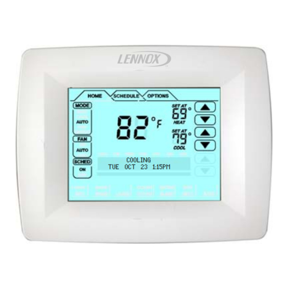
Page 5: Home Screen Current Conditions & Temp. Settings
Home Screen Current Conditions & Temperature Settings The HOME screen (figure 2) displays indoor temperature and outdoor temperature if the outdoor sensor is installed. Other system operational information, such as indoor relative humidity (if turned on in user set- tings), dehumidifying, cooling or heating, will alternately be displayed in the information display. -
Page 6: Controlling The Heat/Cool Modes Of Operation
Controlling Heat/Cool Modes of Operation On initial power up or after an a power loss over 2 When the faults, errors, and service information displays appear, dy- hours, the thermostat powers up at the HOME namic keys will appear under the second line entries, REMIND, screen in the AUTO position. -
Page 7: Controlling The Fan Operation
Controlling the Fan Operation Fan Modes percentage of active time per hour, during periods of equipment inactivity (i.e., heating or cooling equipment not running). The fan is ON If backlight is not on continuous, press the screen for 5 minutes at a time. The user may change the percentage of ON time anywhere to turn on the backlight. -
Page 8: Schedule Tab Programming
Schedule tab Programming If backlight is not on continuous, press the screen anywhere to turn on Programming may be performed in groups of days or individual days, the backlight. Press the SCHEDULE tab along the top of the screen. as follows: The display changes to programming mode (figure 4) and shows the A MON TO SUN −... - Page 9 Schedule tab Programming (continued) Days & Events Programming process Action Display shows... Press SCHEDULE tab SCHEDULE screen Press EDIT UP/DOWN arrows on right−hand side of screen; EDIT changes to CANCEL Press NEXT to highlight the de- Days change to match selected sired grouping of days group, e.g.
-
Page 10: Options Tab Reminders & User Settings
Options tab Reminders/User Settings CLEAN button [ User Settings [ OPTIONS TAB > [CLEAN] OPTIONS TAB > USER SETTINGS > [ENTER] When you select the OPTIONS tab, two buttons appear near the bot- 12 OR 24 HOUR Page 10 Page 10 tom of the screen labeled CLEAN and ENTER. - Page 11 Options tab User Setting (continued) EVENTS DAILY 2 OR 4 default is 4; to change, scroll to EVENTS For OUTDOOR TEMP, select ON or OFF; then press SAVE. DAILY 2 OR 4; press ENTER. Use arrows to change to 2; press SAVE. OUTDOOR TEMP EVENTS DAILY 2 OR 4 DEFAULT(OFF)
- Page 12 Options tab User Setting (continued) COOLING LIMIT This limits the temperature at which the thermostat BACKLIGHT INTENSITY default is 100%; scroll to BACKLIGHT IN- may be set for cooling (default is 50º); to change to any degree between TENSITY; press ENTER. Use arrows to change to 20 to 100% in 20% 45ºF and 90ºF, scroll to COOLING LIMIT;...
-
Page 13: Options Tab Installer Settings
Options tab Installer Settings Installer Settings SYSTEM SETUP Sets the thermostat for operation with a heat pump or non-heat pump and defines the number of compressor stages and OPTIONS TAB > INSTALLER SETTINGS > [ENTER] [ENTER] the number of backup heat stages. The default settings for the system are Non−heat Pump, Gas/Oil, 2 compressor stages, 2 indoor heat COMPRESSOR PROTECT Page 17... - Page 14 Options tab Installer Settings (continued) RESIDUAL COOL default is zero seconds. This is the time, in sec- SMOOTH SET BACK (SSR) default is OFF. When enabled, smooth onds, that the fan runs after a call for cooling is satisfied in order to deliv- set back begins recovery up to 2 hours before the programmed time so er any residual cooling ability from the coil and ductwork into the condi- that the programmed temperature is reached at the corresponding pro-...
- Page 15 Options tab Installer Settings (continued) Table 1. Smooth Set back Recovery (SSR) & SSR Stg 2 Lock Out Operation Equipment Available SSR = Enabled; SSR Stg 2 lock out = enabled SSR = Enabled; SSR Stg 2 lock−out = disabled (off) 1 stage HP with 1 or 2 stages Run HP (Y1) only;...
-
Page 16: Resetting Program To Factory Conditions
Options tab Installer Settings (continued) DAYLIGHT SAVING TIME (DST) default setting is ON (enabled). CUSTOM REMINDER 1 or 2. Press ENTER. To create a reminder, Note: Beginning in 2007, DST will begin on the second Sunday in March press EDIT. and end the first Sunday in November. -
Page 17: Epa Energy Star ® Recommended Setpoints
Options tab Installer Settings (continued) ® ENERGY STAR DEFAULT EPA ENERGY STAR recommended HUMIDITY OFFSET default is 0%. This can be used to offset the dis- setpoints for heating and cooling can help the household save energy. played and controlled space relative humidity (RH) by up to +/− 10% The following time and temperatures are preprogrammed into the con- RH. - Page 18 Options tab Installer Settings (continued) SYSTEM TEST MODES After the thermostat has been installed and All HVAC components can be tested to confirm the signals between set−up, the installer may run a system test function (accessed through thermostat and unit are being sent and were received. the installer settings menu), to test all cooling, heating, Emergency NOTES −...
-
Page 19: Humidification
Humidification INSTALLER SETTINGS Default setting is 45% RH. Use up/down arrows to define what NEW SETPOINT IS (between 15 to 45%); then press SAVE. Humidification (adding moisture to air) is provided only when the ther- HUM SETPOINT mostat is in heat mode. The humidification signal (H terminal) to the hu- DEFAULT (45%) midifier (off when the thermostat is in the COOL mode) controls humidi- fication. - Page 20 Humidification (continued) USER SETTINGS Scroll to HUMIDITY SETTINGS; press ENTER. Press the box below HUMIDIFY. BASIC & PRECISION if set up by the installer settings for BASIC or HUMIDITY MODE PRECISION, this adjustment controls the relative humidity (RH) be- HUMIDIFY DEHUMIDIFY tween 15 and 45%.
-
Page 21: Dehumidification
Dehumidification INSTALLER SETTINGS In PRECISION mode, dehumidification occurs if all BASIC conditions are true, except cooling demand may or may not be present. Maximum Dehumidification (removing moisture from air) can occur only when the over cool from cooling set point is 2ºF. thermostat is in cool mode. -
Page 22: Humiditrol ® Enhanced Dehumidification Accessory (Eda)
Dehumidification (continued) The AUX setting is used when a whole home dehumidifier is used for If OFF is selected by the installer settings for DEHUMIDIFY but HU- dehumidification. This requires: MIDIFY is on, the humidification menu appears (this setpoint adjust has NO effect on dehumidification): whole home dehumidifier has been wired to thermostat per dehu- HUM SETPOINT... - Page 23 Dehumidification (continued) ® ComfortSense Model L7742U thermostat operation Y2" terminal (if available) becomes activated with 24VAC. This will cycle the indoor variable speed motor to the dehumidification speed with Humiditrol enabled and cycle Y2 ON" to the outdoor unit. Cooling calls have priority over ®...
-
Page 24: Stage Delay And Differential Settings
Stage Delay & Differential Settings (Installer settings) Press OPTIONS tab for the main options screen, then use the arrows to When OFF is selected all stage delay timers are disabled. This means select INSTALLER SETTINGS. Press ENTER. stages are changed based on the temperature and not their timer de- lays. - Page 25 Stage Delay & Differential Settings (Installer settings) (continued) H/C STGS LOCKED IN default NO (heat/cool stages are turned off Configuration Figure separately). If changed to YES, heat/cool stages are turned off together Multi−stage Cooling for Heat Pump/Non−Heat Pump (see figures 6 through 13). Scroll to H/C STGS LOCKED IN; press EN- TER.
- Page 26 Stage Delay & Differential Settings (Installer settings) (continued) 1st stage 1st stage Stages Stg1 Differential Locked = 2nd stage 2nd stage Stg2 Differential 1st stage 1st stage Stages Stg1 Differential Locked = 2nd stage 2nd stage Stg2 Differential SET- SP −3.0 SP −2.5 SP −2.0 SP −1.5...
- Page 27 Stage Delay & Differential Settings (Installer settings) (continued) 1st stage 1st stage Stages Stg1 Differential Locked = 2nd stage 2nd stage Stg2 Differential 3rd stage 3rd stage Stg3 Differential 4th stage 4th stage Stg4 Differential 1st stage 1st stage Stages Stg1 Differential Locked = 2nd stage...
- Page 28 Stage Delay & Differential Settings (Installer settings) (continued) 1st stage 1st stage Stages Stg1 Differential Locked = 2nd stage 2nd stage Stg2 Differential 3rd stage 3rd stage Stg3 Differential 1st stage 1st stage Stages Stg1 Differential Locked = 2nd stage 2nd stage Stg2 Differential 3rd stage...
- Page 29 Stage Delay & Differential Settings (Installer settings) (continued) 1st stage 1st stage Stages Stg1 Differential Locked = 2nd stage 2nd stage Stg2 Differential 3rd stage 3rd stage Stg3 Differential 1st stage 1st stage Stages Stg1 Differential Locked = 2nd stage 2nd stage Stg2 Differential 3rd stage...
- Page 30 Stage Delay & Differential Settings (Installer settings) (continued) 1st stage 1st stage Stages Stg1 Differential Locked = 2nd stage 2nd stage Stg2 Differential 3rd stage 3rd stage Stg3 Differential 4th stage 4th stage Stg4 Differential 1st stage 1st stage Stages Stg1 Differential Locked = 2nd stage...
-
Page 31: Temporary Temperature Change (Pausing The Schedule)
Temporary Temperature Change (Pausing the Schedule) Two types of temperature changes may be made: temporary (while in 5. After the 3 hours expires, the scheduled programming will re- sume, OR, press SCHED to cancel the hold. the SCHEDule ON mode) or permanent (while in SCHEDule OFF). Permanent Temperature Changes (schedule OFF −... -
Page 32: Optional Remote Outdoor Sensor
Optional Remote Outdoor Sensor The outdoor sensor (X2658) may be required, especially when using the heat pump system, the remote outdoor sensor helps determine Humiditrol® EDA applications. In addition to measuring and displaying when to turn on the second stage of heating for optimal comfort. outdoor temperature, the outdoor sensor provides dew point adjust- When the outdoor sensor is connected, the temperature displays in the ment and control for all models. -
Page 33: Service Reminders
A label on the back of the thermostat is visible through an opening in the may be reset (to default) or delayed (snooze) at any time: back of baseplate. This identifies the Lennox Catalog Number, Part Replace Media Filter Number and Serial Number. Separate the baseplate from the thermo- Routine Sys (System) Check−up... -
Page 34: Appendix A. Flow Diagrams & Wiring Diagrams
Appendix A. Flow Diagrams and Wiring Diagrams ® ® Figure 15. ComfortSense Model L7742U Thermostat Operation with Humiditrol EDA Enabled START HUMIDITROL RUN EQUIPMENT IN there a cooling NORMAL COOLING Is indoor demand MODE temperature > 2ºF above heating set point RUN EQUIPMENT IN NORMAL HEATING... - Page 35 START Figure 16. Dual Fuel Flowchart Indoor heat De−energize demand W1 and W2 LEGEND HBSP − High Balance Set Point Gas/oil heat (non−HP) HEAT PUMP LBSP − Low Balance Set Point demand (W1) or EM LOCKOUT heat demand ODT − Outdoor Temperature NOTES Energize 1st stage gas/oil heat...
-
Page 36: Wiring Diagrams
Wiring Diagrams ® Thermostat wiring connections with various units, including dual fuel, zone control, and applications that include the Humiditrol Enhanced Dehu- midification Accessory (EDA). See figures 17, 18 and 19. For whole home dehumidifier, refer to the installation instruction for the dehumidifier. Figure 17. - Page 37 Figure 18. CBX40UHV Wiring Diagrams Page 37 ComfortSenset Model L7742U Touch Screen 7−Day Programmable Thermostat...
- Page 38 Figure 19. Thermostat Wiring Diagrams Page 38 506228−01 05/09...
-
Page 39: Appendix B. Diagnostic Info. & Available System Settings
Appendix B. Diagnostic Information and Hidden Menu Tables Diagnostic Information Table Action to Clear / Recovery Condition Display Text (Screen1) Display Text (Screen2) System Action Condition AC power loss for more Lithium Battery will remember the When AC power is restored, normal than 250ms (1/4 second) clock for 30 days. - Page 40 Action to Clear / Recovery Condition Display Text (Screen1) Display Text (Screen2) System Action Condition Outdoor Sensor error with NO OUTDOOR SENSOR No Humiditrol or Humidity operation If the outdoor sensor reads a value ® Humiditrol enabled (OR REMIND SERVICE REMIND/SERVICE is run.
- Page 41 Action to Clear / Recovery Condition Display Text (Screen1) Display Text (Screen2) System Action Condition Humiditrol and Dew point NO OUTDOOR SENSOR The display of Outdoor sensor from If the outdoor sensor reads a value disable and Outdoor sen- REMIND CLEAR SERVICE REMIND/CLEAR/SERVICE HOME will be turned OFF.
- Page 42 Action to Clear / Recovery Condition Display Text (Screen1) Display Text (Screen2) System Action Condition Media Filter REPLACE MEDIA FILTER See REMIND/RESET notes Displayed on both lines on HOME. User either push RESET or RE- REMIND RESET MINDER button UV Lamp REPLACE UV LAMP See REMIND/RESET notes Displayed on both lines on HOME.
- Page 43 Action to Clear / Recovery Condition Display Text (Screen1) Display Text (Screen2) System Action Condition Indoor Humidity (when INDOOR RH XX% Displayed on first line. Second line Is user de−selects from User set- selected from User set- Date/Time has Date/Time info on it tings or higher priority reminder/er- tings) ror occurs...
- Page 44 Available System Settings Setup HEAT PUMP Configurations NON HEAT PUMP Configurations Backup/ Indoor Gas/ Gas/ None Gas/ Gas/ None Elec Elec None Elec Elec None G/O or G/O or None G/O or G/O or None Heat Elec Elec Elec Elec Comp.
Need help?
Do you have a question about the ComfortSense L7742U and is the answer not in the manual?
Questions and answers