Table of Contents
Advertisement
Quick Links
E2007 Lennox Industries Inc.
Dallas, Texas, USA
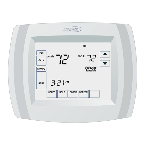
ComfortSenset 5000 Series Model No. L5732U
This thermostat is to be installed by a qualified service technician or
other qualified agency in accordance with the manufacturer's instruc-
tions, all codes, and requirements of the authority having jurisdiction.
506068−01
2/2008
3 Heat / 2 Cool Programmable
Touch Screen Thermostat
WARNING
INSTALLATION
INSTRUCTIONS
Advertisement
Table of Contents

Subscribe to Our Youtube Channel
Related Manuals for Lennox ComfortSense L5732U


Summary of Contents for Lennox ComfortSense L5732U
- Page 1 INSTALLATION INSTRUCTIONS E2007 Lennox Industries Inc. Dallas, Texas, USA ComfortSenset 5000 Series Model No. L5732U 3 Heat / 2 Cool Programmable Touch Screen Thermostat WARNING This thermostat is to be installed by a qualified service technician or other qualified agency in accordance with the manufacturer’s instruc- tions, all codes, and requirements of the authority having jurisdiction.
-
Page 2: Table Of Contents
..Page 20 Hammer General Electrical tape The Lennox ComfortSenset 5000 Thermostat Location Series L5732U programmable touch Install the thermostat about 5 feet screen thermostat provides control for (1.5m) above the floor in an area with up to three stages of heating and two good air circulation. -
Page 3: Remove Existing Thermostat
carried on the replacement wall- Remove Existing Thermostat plate. If this thermostat is being used to re- Do not allow the thermostat wires place an existing thermostat, remove to fall behind the drywall. the old thermostat: 1 − Turn off power at the heating and/ WARNING or cooling system or fuse/circuit breaker panel. -
Page 4: Thermostat Installation
6 − Position the wallplate over the an- Thermostat Installation chors and pull the thermostat The thermostat may be installed hori- wires back through the wiring zontally in a 4 in. X 2 in. (101.6 mm X opening. 50.8 mm) wiring box or on the wall us- 7 −... -
Page 5: Led Indicator
1 − Make wiring connections per the the loosened screws. Securely appropriate wiring diagram on tighten each screw. page 6 or 7. Refer to the table TERMINAL below for terminal designations. BLOCK LETTER DESIGNATIONS Terminal Description Second−stage cooling WALLPLATE Second−stage heating W2 (AUX) (or auxiliary heating) WIRE HOLE... -
Page 6: Field Wiring Diagrams
Field Wiring Diagrams TYPICAL CONVENTIONAL MULTI−STAGE APPLICATION TWO−STAGE HEAT / TWO−STAGE COOL TYPICAL MULTI−STAGE HEAT PUMP APPLICATION NO AUXILIARY HEAT TYPICAL MULTI−STAGE HEAT PUMP APPLICATION WITH AUXILIARY HEAT Page 6... - Page 7 Field Wiring Diagrams (Continued) TYPICAL SINGLE−STAGE HEAT PUMP SYSTEM WITH AUXILIARY HEAT TYPICAL SINGLE−STAGE HEAT PUMP SYSTEM WITHOUT AUXILIARY HEAT Page 7...
-
Page 8: Install Batteries
WALLPLATE Install Batteries 1 − Install three provided AAA alkaline batteries in the back of the thermo- PINS ON stat as shown. BACK OF THERMOSTAT BACK OF THERMOSTAT TERMINAL SCREW BLOCK Set Calendar and Clock This thermostat is designed to auto- BATTERIES matically keep the current time and date in memory for up to ten years, un-... - Page 9 Heating Mode Operation Advanced Heat Pump Features Outdoor Temp. below Balance Point When the outdoor temperature is be- The thermostat installer set−up may be low the selected balance point, only configured in several different ways to the furnace (fossil fuel) operates to sat- ensure the desired system operation.
- Page 10 Heat Pump Application When the outdoor temperature is Electric Auxiliary Heat above the auxiliary lock−out tempera- with Outdoor Temperature Sensor ture (balance point), only the compres- sor operates. Installer set−up number 0170 −− heat pump. When the outdoor temperature is be- tween the two temperatures, both the Installer set−up number 0200 −−...
-
Page 11: Installer Set−Up
Installer Set−Up Use the following steps and the Install- ADVANCE TO NEXT INSTALLER INSTALLER SET−UP er Set−Up menu to match the thermo- SET−UP NUMBER CURRENT stat to the HVAC system. SETTING 1 − Press and release the SYSTEM key. 2 − Press and hold the two blank keys on either side of the center blank key for approximately five sec- onds. - Page 12 Instal- Installer Selection Description lerSet− Set−Up Notes (Factory setting in bold print) Up No. Name Select first two digits of current calendar Date year (20 for 2007, etc.) 0120 (Year/ first) Factory setting = 20. Date Select last two digits of current calendar 0130 (Year/ year (07 for 2007, etc.);...
- Page 13 Instal- Installer Selection Description lerSet− Set−Up Notes (Factory setting in bold print) Up No. Name Available only if 0 − Gas or Oil Heat −− Heating system conventional controls fan during heating demand. system chosen. Factory setting. Control 0180 Setting defaults Heating to electric heat 1 −...
- Page 14 Instal- Installer Selection Description lerSet− Set−Up Notes (Factory setting in bold print) Up No. Name Cycles per Hour 1 − Recommended for use with steam and (cph) 2nd gravity. Stage Conven- 3 − Recommended for use with hot water tional heat and high−efficiency (90% or higher) Shown only Heating...
- Page 15 Instal- Installer Selection Description lerSet− Set−Up Notes (Factory setting in bold print) Up No. Name 0 − Manual changeover from heating mode to cooling mode. Factory setting. Change- 0300 over 1 − Auto−changeover from heating mode to cooling mode. 2 − 2°F (1.5°C) Dead- 3 −...
- Page 16 Instal- Installer Selection Description lerSet− Set−Up Notes (Factory setting in bold print) Up No. Name 0 − No auxiliary heat lock−out. Factory Shown only if setting. electric is se- Heat 40°F (4.5°C). lected for back− Pump up heat source 45°F (7°C) 0360 Auxiliary and outdoor...
- Page 17 Instal- Installer Selection Description lerSet− Set−Up Notes (Factory setting in bold print) Up No. Name Heat Settings of 40 − 90 available in 1°F in- Tempera- Shown in 1/2°C creme. 0600 ture increments Range Factory setting = 90.nts. (°F) Cool Settings of 50 −...
- Page 18 Instal- Installer Selection Description lerSet− Set−Up Notes (Factory setting in bold print) Up No. Name 1 − Less aggressive control. (Cooling may Cooling turn off before setpoint reached). Mode Applies to re- 2 − Standard control. Factory setting. 0690 Tempera- covery ramp.
-
Page 19: System Test
System Test The system test function allows the in- 4 − The installer test number is dis- staller to check the HVAC system after played on the upper portion of the the thermostat set−up has been com- screen. Press the up or down ar- pleted. -
Page 20: Troubleshooting
Troubleshooting Symptom Possible Cause Action 1− Check to see that there is 24V between R and C terminals. Display does not come Thermostat is not being powered. 2− Check to see that bat- teries are properly installed. 1− Check temperature set- points.
Need help?
Do you have a question about the ComfortSense L5732U and is the answer not in the manual?
Questions and answers