
Related Manuals for Maxlogic ML-221XX series


Summary of Contents for Maxlogic ML-221XX series
- Page 1 COMMISSIONING, OPERATING AND MAINTENANCE MANUAL MODEL: MAXLOGIC SERIES SUB MODEL: CONVENTIONAL SYSTEM FIRE ALARM CONTROL PANEL...
-
Page 2: Table Of Contents
CONTENTS Section Page Introduction Warning Mounting Inputs Outputs Controls Indicators Fuses Panel conditions Menu Modes Technical Specifications Santral Models Accessories and Options Annex - A : Panel Wiring Diagram Annex Annex - B : Panel Dimensions Annex - C1 : Panel Serigraphy Annex - C2 : Panel Serigraphy Annex - C3 : Panel Serigraphy Annex - C4 : Panel Serigraphy... -
Page 3: Introduction
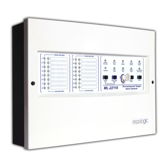
1- INTRODUCTION Maxlogic ML-221XX series conventional fire alarm control panel has, 2, 4, 8, 12 ve 16 zones (detection circuits) according to model with 24V DC operating voltage. Power supply of panel has an automatic battery charger and charger control circuit. Fire and fault conditions for each zone are indicated by individual LEDs on the fascia. -
Page 4: Mounting
3- MOUNTING The chosen site for the mounting of the panel must be clean, dry and not subject to shock or vibration. The panel must not be mounted near to sources of excessive heat or cold (see the specifications). Mark the position of the fixing holes according to the respective Annex, ensuring that the wall is flat at the chosen location. -
Page 5: Controls
5.3.1 FIRE RELAY: The fire relay activates on fire condition. The output is returned to its initial position by pressing Reset button provided no fire condition is available. The fire relay is normally not energised. 5.3.2 FAULT RELAY: The fault relay activates on fault condition. The output returns to its initial position automatically as soon as fault condition ends. Fault relay is normally energised;... -
Page 6: Fuses
Disable Flashing indicates any disablement condition. Sounder Fault Illumination indicates open or short circuit on the sounder output. Zonal faults Illumination indicates; Short circuit on the zone cabling, Open circuit, Connection problems between detector and base, End of line resistor wiring problems 8- FUSES SOUNDER OUTPUT FUSE (F2,F3) The self-resetting fuse activates on 0.5А... -
Page 7: Menu Modes
10- MENU MODES 10.1. TEST MODE In Test Mode, manually initiated fire condition is automatically reset in a few seconds by the panel. The Test Mode causes continuous illumination of the respective zonal Fault LED. Steps taken for entering and quitting the Test Mode are as follows: - Set the Button Control key to Enable position. -
Page 8: Santral Models
MLY-2218 2 way sounder card 13.1 - 8 way Relay card (MLY-2210) • Relay module provides zonal relay output for Maxlogic ML-221XX series conventional panels. • Relay outputs 30 V DC 1A. 8 way Relay card (MLY-2210) Wiring Diagram KK-642.042 Rev.No:0 01.11.12 ML-221XX User Manual... - Page 9 13.2 - 8 way Sounder card (MLY-2211) • Sounder module provides zonal sounder output for Maxlogic ML-221XX series conventional panels. • Each sounder output has 24V DC 100 mA. 8 way Sounder card (MLY-2211) Wiring Diagram 13.3 - Network Card (MLY-2212) Network module provides to makenetwork connection up 32 panels with MGRP-64 Repeater panel.
- Page 10 Network Card (MLY-2212), Mermory Card (MLY-2213), Network and Memory Card (MLY-2214) Wiring Diagram KK-642.042 Rev.No:0 01.11.12 ML-221XX User Manual Page 10/16...
-
Page 11: Annex Annex - A : Panel Wiring Diagram
KK-642.042 Rev.No:0 01.11.12 ML-221XX User Manual Page 11/16... -
Page 12: Annex - B : Panel Dimensions
KK-642.042 Rev.No:0 01.11.12 ML-221XX User Manual Page 12/16... -
Page 13: Annex - C1 : Panel Serigraphy
KK-642.042 Rev.No:0 01.11.12 ML-221XX User Manual Page 13/16... -
Page 14: Annex - C2 : Panel Serigraphy
KK-642.042 Rev.No:0 01.11.12 ML-221XX User Manual Page 14/16... -
Page 15: Annex - C3 : Panel Serigraphy
KK-642.042 Rev.No:0 01.11.12 ML-221XX User Manual Page 15/16... -
Page 16: Annex - C4 : Panel Serigraphy
KK-642.042 Rev.No:0 01.11.12 ML-221XX User Manual Page 16/16...
Need help?
Do you have a question about the ML-221XX series and is the answer not in the manual?
Questions and answers