Table of Contents
Advertisement
Quick Links
Advertisement
Table of Contents

Related Manuals for Maxlogic ML-22108


Summary of Contents for Maxlogic ML-22108
- Page 1 2831 EN 54-2:1997+A1:2006 DOP.22110201 EN 54-4:1997+A1:2002 DOP.22110202 +A2:2006 DOP.22110203 926d/05, 926d/06 DOP.22110204 926d/07, 926d/08 COMMISSIONING, OPERATING AND MAINTENANCE MANUAL MODEL: MAXLOGIC SERIES SUB MODEL: CONVENTIONAL SYSTEM FIRE ALARM CONTROL PANEL...
-
Page 2: Table Of Contents
CONTENTS Section Page Introduction Warning Mounting and Installing Commissioning Inputs Panel Outputs Controls Indicators Fuses Panel conditions Menu Modes Working with Repeater Panel and Relay Module Information About Usage Faults Panel Models Accessories and Options Technical Specifications List Of Compatible Site Devices System Faults Terms Battery Charge Voltage Adjustment Statement By The Ambient Temperature... -
Page 3: Introduction
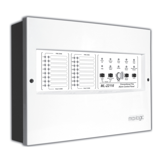
1 - INTRODUCTION Maxlogic ML-221XX series conventional fire alarm control panel has, 2, 4, 8 and 16 zones (detection circuits) according to model with 24V DC operating voltage. Max. 512 pcs detector can be connected into the panel. Power supply of panel has an automatic battery charger and charger control circuit. Fire and fault conditions for each zone are indicated by individual LEDs on the fascia. -
Page 4: Warning
- Measuring battery charge current, - Battery load test b. Supplying card test - The operation status test from the battery - Battery fault location test c. Battery supplying voltage test 2. Control panel visual test 3. Cleaning the panel 4. -
Page 5: Mounting And Installing
SIGNS USED ON THE DEVICE Sıgn Description Dangerous Voltage 230V AC Rated Voltage Protective Earth Attention! Static Safeguarded Work Area Two units 12V 7Ah battery required 3 - MOUNTING AND INSTALLING System should be installed by experienced and professional personal. Also following details should be considered; •... -
Page 6: Commissioning
4 - COMMISSIONING 4.1 Control list before commissioning 1. Technical staff should check the followings before commissioning; • All cable connections should be controlled on the field. • Detectors and call points should be controlled whether the connections are done. •... -
Page 7: Inputs
5 - INPUTS 5.1 MAINS POWER SUPPLY The system is designed to operate with 230V AC 50Hz. Earth connections must be made to earth terminal and earth resistor must be less than 10 PHASE 230V AC 50Hz Ω. The mains supply of the panel must be via an independent self-reset- EARTH Mains power supply input... -
Page 8: Controls
6.2 AUXILIARY POWER SUPPLY OUTPUT The panel is equipped with an auxiliary 0.5А 24V DC power supply output. The output is used for energizing external devices such as EXTERNAL DEVICE telephone dialer or gas detector. Connecting an external device with improper voltage requirement or overloading the output will cause device malfunction or output fault. -
Page 9: Indicators
8 - INDICATORS 8.1 Power On Continuous illumination indicates that the panel is energized. Power General Power System Earth Fault Fault Fault Fault 8.2 General Fault “Illumination indicates any fault condition. Silence Disable Silence Sounder Fault/ FIRE Alarm Buzzer Disable 8.3 Power Fault “Illumination indicates power supply fault condition. -
Page 10: Fuses
8.12 Fault Zone If there is intermittently indicating, it means there is a zonal fault. Reason of the faults can be the followings. 1. Zone cables Clemens connection interrupting. 2. Zone cable short circuit. 3. Zone cable line interrupting. 4. If there is a detector which is removed from the base. 5. -
Page 11: Working With Repeater Panel And Relay Module
- Set the Button Control key to Disable position. - Same steps are repeated and zone or sounder is commissioned in order to take again normal condition of the disabled zone or sounder. - “Fault LED” turns OFF when the feature is deactivated. Note: Panel should be in quiescent status in order to activate disable function. - Page 12 15.1 - 8 way Relay card (MLY-2210) • Relay module provides zonal relay output for Maxlogic ML-221XX series conventional panels. • Relay outputs 30V DC 1A. This specification beyond the scope of EN 54-2 standart tests. 8 way Relay card (MLY-2210) Wiring Diagram 15.2 - 8 way Sounder card (MLY-2211)
- Page 13 COMMUNICATION CARD CONFIGURATION Addressing process can be done manually via communication module.In order to do that, after the panel connection, 6. MAN/PC switch position should move to ON(MAN) position and address should be assigned as between 1-32 then panel should be energized after the addressing process.
-
Page 14: Technical Specifications
16 - TECHNICAL SPECIFICATION Output Descriptions Fire Alarm Relay: 30V DC 1A Fault Relay: 30V DC 1A Sounder Output Power: 24V DC 1A External Power Supply Output: 24V DC 500 mA Power Supply Descriptions Output Power: Main Supply: 230V AC 50 Hz Nominal Load Output: 20°C, 27,3V DC (18V min - 30V max) temperature Compensated 230V AC Fuse:... -
Page 15: List Of Compatible Site Devices
MaviGard conventional multi-sensor detector MG-3500 MaviGard universal detector base ML-2110 MaxLogic conventional photo-electric smoke detector ML-2120 MaxLogic conventional combined heat (rate of rise) detector ML-2130 MaxLogic conventional fixed heat detector ML-2140 MaxLogic conventional multisensor detector (photo-electric smoke+heat) MaxLogic detector mounting base... -
Page 16: Terms
19 - TERMS Amp - Current Volt - Voltage Watt - Power Alternative current Direct Current Amp / Hour - Battery Capacity Milliamps Second Millimeter Meter Kilogram Lighting diode Computer 20 - BATTERY CHARGE VOLTAGE ADJUSTMENT STATEMENT BY THE AMBIENT TEMPERATURE Temperature (°C) Maximum (V) Minimum (V) -
Page 17: Power Supply And Connections
21 - POWER SUPPLY AND CONNECTIONS ML-221XX Conventional Panel Thermistor connection is made to this point BATTERY BATTERY 12V DC 7Ah 12V DC 7Ah 22 - COMMUNICATION / EVENT REGISTRATION CARD CONNECTION Address Setting Manuel/PC Setting MLY-2212 Communication Card MLY-2214 Communication / Event Registration Card... -
Page 18: Annex-A: Panel Connection Diagram
KK-642.042 Rev.No:17 19.01.24 ML-221XX User Manual 18/21... -
Page 19: Annex-B: Panel Dimensions
KK-642.042 Rev.No:17 19.01.24 ML-221XX User Manual 19/21... -
Page 20: Annex-C1: Panel Serigraphy
Annex - C1: Panel Serigraphy Annex - C2: Panel Serigraphy KK-642.042 Rev.No:17 19.01.24 ML-221XX User Manual 20/21... -
Page 21: Annex-C3: Panel Serigraphy
Annex - C3: Panel Serigraphy Annex - C4: Panel Serigraphy ML-22102 ML-22104 ML-22108 ML-22116 2831 Mavili Elektronik Ticaret ve Sanayi A.Ş. Şerifali Mahallesi, Kutup Sokak No:27/1-2-4 Ümraniye TR-34775 İSTANBUL DOP No.: DOP.22110201 DOP No.: DOP.22110202 DOP No.: DOP.22110203 DOP No.: DOP.22110204 DOC No.: DOC.22110201 DOC No.: DOC.22110202 DOC No.: DOC.22110203...
Need help?
Do you have a question about the ML-22108 and is the answer not in the manual?
Questions and answers