Table of Contents
Advertisement
Quick Links
Advertisement
Table of Contents

Summarization of Contents
Introduction and Manufacturer Information
Manufacturer and Certification Body Details
Company details for the manufacturer and certification body.
Product Disposal Guidelines
Information on proper disposal of packaging and electronic waste.
Warnings and Precautions
Handling, Storage, and Transportation Warnings
Safety guidelines for handling, storing, and transporting the control panel.
Maintenance and Daily Checks
Requirements for periodic maintenance and daily user checks of the panel.
Testing and Commissioning Procedures
Panel and Field Device Testing
Procedures for testing control panel and field devices.
Safety Warning Signs
Explains critical safety signs like electrical shock and ESD protection.
Commissioning Process Overview
General steps and overview for commissioning the fire alarm system.
Device Identification and Installation
Device Warning Signs
Explains symbols and labels found on the device.
Mounting and Installation Guidelines
Detailed instructions for physically mounting and installing the control panel.
Commissioning Procedures
Pre-Commissioning Checks
List of checks to perform before starting the commissioning process.
Cable Connection Verification
Steps to verify cable connections for zones and sounders.
Sounder and Zone Commissioning
Specific steps for commissioning sounder outputs and zone lines.
System Inputs
Mains Power Supply Input
Details on connecting the main 230V AC power supply to the panel.
Battery Inputs
Information on connecting the 12V DC batteries for backup power.
Detection Zone Inputs
How to connect detectors and call points to the detection zones.
Panel Outputs
Sounder Output
Specifications and connection of the supervised sounder output.
Panel Outputs (continued)
Auxiliary Power Supply Output
Details on the 24V DC auxiliary power output for external devices.
Relay Outputs (Fire & Fault)
Explanation of the fire and fault relay outputs and their usage.
Control Functions
Panel Control Buttons
Description of the function of each button on the control panel.
Indicator Lights
Power and Fault Indicators
Explains the Power On, General Fault, Power Fault, System Fault, Earth Fault LEDs.
Fire and Alarm Status Indicators
Describes the Fire, Alarm Silence, and Buzzer Silence LEDs.
Zone Status Indicators
Details on Zone Fire and Zone Fault/Disablement LEDs.
Indicator Lights and Panel States
Fault Zone Indicator Details
Explains intermittent and permanent indications for Fault Zone LEDs.
Fuse Descriptions
Information on the panel's internal fuses and their functions.
Normal, Fire, and Fault Panel States
Describes the visual indicators for normal, fire, and fault conditions.
Menu Modes
Disable Mode Operation
Steps to enable and disable zones or sounders using the menu.
Menu Modes and System Features
Exiting Disable Mode
Procedure to return disabled zones or sounders to normal operation.
Repeater Panel and Relay Module Integration
Compatibility with repeater panels and relay modules.
Usage Fault Information
Common faults and potential causes for panel damage.
Available Panel Models
List of different Maxlogic ML-221XX panel models and their zone capacities.
Accessories and Options
Overview of optional accessories and add-on cards for the panel.
Accessories and Options Details
Relay and Sounder Module Cards
Details on 8-way relay and sounder module cards.
Network and Memory Cards
Information on network, memory, and combined network/memory cards.
Communication Configuration
Manual Communication Card Addressing
Procedure for manually setting panel addresses via DIP switches.
Network Wiring Diagram
Wiring diagram for network communication setup.
Technical Specifications
Output and Power Supply Specs
Detailed specifications for panel outputs and power supply.
Battery Specifications
Technical details regarding battery types, capacity, and charging.
Network and PC Communication Specs
Specifications for network and PC communication interfaces.
Environmental and Mechanical Specs
Operating environment conditions and mechanical dimensions.
Compatible Devices and System Faults
List of Compatible Site Devices
Catalog of detectors, call points, and sounders compatible with the panel.
System Fault Conditions and Actions
Describes system fault indicators and automatic actions.
Service Actions for System Faults
Procedures for service personnel to follow when a system fault occurs.
Glossary and Battery Charging
Technical Terms Glossary
Definitions of common technical terms used in the manual.
Battery Charge Voltage vs. Temperature
Table showing battery charge voltage adjustment based on ambient temperature.
Power and Communication Connections
Power Supply and Battery Connections
Visual guide for connecting power supply and batteries.
Communication Card Connection
Diagram showing how to connect communication cards to the mainboard.
Panel Wiring Diagrams
Annex A: Panel Wiring Diagram
Detailed wiring diagram for the panel's internal connections.
Panel Dimensions
Annex B: Panel Dimensions
Technical drawings showing the physical dimensions of the panel.
Panel Serigraphy
Annex C1: Panel Serigraphy (ML-22102)
Layout and labeling of components for the ML-22102 model.
Annex C2: Panel Serigraphy (ML-22104)
Layout and labeling of components for the ML-22104 model.
Panel Serigraphy (continued)
Annex C3: Panel Serigraphy (ML-22108)
Layout and labeling of components for the ML-22108 model.
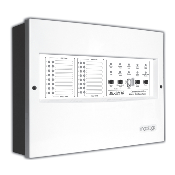
Annex C4: Panel Serigraphy (ML-22116)
Layout and labeling of components for the ML-22116 model.


Need help?
Do you have a question about the ML-22104 and is the answer not in the manual?
Questions and answers