Table of Contents
Advertisement
Quick Links
Advertisement
Table of Contents

Related Manuals for Maxlogic ML-22102


Summarization of Contents
Introduction and Product Information
Product Overview and Standards Compliance
Details the Maxlogic ML-221XX series fire alarm control panel, its features, and compliance with EN 54 standards.
Manufacturer, Service, and Certification Details
Provides contact information for the manufacturer, authorized service provider, and certification body.
Disposal of Packaging and E-Waste
Guidelines for the responsible disposal of packaging materials and the electronic waste unit.
Safety and Operational Precautions
Handling, Storage, and Transportation Safety
Safety measures for handling, storing, and transporting the fire alarm control panel to prevent damage.
Operational Safety and Maintenance Procedures
Crucial warnings for operation, cleaning, and necessary periodic maintenance for the control unit.
Commissioning and Testing Procedures
Control Panel and Field Device Testing
Comprehensive tests for control panel functions, LEDs, access levels, and connected field devices.
Warning Signs and Electrical Safety
Highlights safety warnings for electrical shock, ESD protection, and proper grounding procedures.
System Commissioning Steps
Details the final system check required after the commissioning process is completed.
Mounting and Electrical Safety
Installation Requirements and Guidelines
Covers IEE directive, field requirements, and general installation guidelines for system setup.
Electrical Safety and Power Connections
Details mains supply requirements, earth connections, fuses, cable types, and safe connection practices.
Panel Mounting Procedures and Location
Guidance on selecting a mounting site, fixing the cabinet, and preparing cable entries for installation.
Commissioning Procedures
Pre-Commissioning Checks and Documentation
Lists essential checks, required documentation, and overview of the commissioning process steps.
Cable Connection Control and Verification
Procedures for controlling cable connections, checking for earth leakage, short circuits, and polarization.
Sounder and Zone Commissioning Steps
Detailed steps for commissioning sounders and zone lines, including fault simulation and alarm activation.
Panel Inputs and Outputs
Mains Power and Battery Supply
Details the requirements for mains power supply, battery connections, and automatic charging circuits.
Detection Zone Inputs Configuration
Explains zone circuit functionality, device connections, capacity, and end-of-line resistor requirements.
Sounder Output Specifications
Describes the supervised sounder output, its limitations, cable requirements, and end-of-line resistor.
Auxiliary Outputs and Control Functions
Auxiliary Power Supply and Relay Outputs
Details the auxiliary 24V DC output and the fire/fault relay outputs, including their specifications and usage.
Control Panel Button Functions
Explains the operation of the Lamp Test, Silence Alarm, Silence Buzzer, and Reset buttons on the control panel.
Button Control Key Operation
Describes how to use the Button Control key to enable panel buttons and activate specific functions.
Panel Indicators and Zone Status
Power and Fault Indicator LEDs
Explains the Power On, General Fault, Power Fault, System Fault, and Earth Fault indicator LEDs.
Status and Silence Indicator LEDs
Details the Fire, Alarm Silence, Disable, Buzzer Silence, and Sounder Fault/Disable indicator LEDs.
Zone Fire and Fault/Disablement Indicators
Describes the indicators for individual fire zones and zone fault/disablement status.
Faults, Fuses, and Panel States
Zone Fault Indicators and Reasons
Explains the meaning of zone fault LEDs and the common reasons for intermittent or permanent fault indications.
Fuse Protection and Specifications
Details the fuses for auxiliary power, sounder output, battery, and mains supply, including their ratings and functions.
Panel Operational States and Conditions
Describes the normal, fire, and fault conditions of the panel and how indicators and outputs behave.
Disable Mode Operation
Instructions for enabling and disabling zones or sounders using the panel's menu modes.
Advanced Features and Fault Information
Zone and Sounder Disablement Procedures
Detailed steps for enabling and disabling specific zones or sounders via the panel's menu modes.
Repeater Panel and Module Compatibility
Information on compatibility with repeater panels, network connections, and module connections.
Common Usage Faults and Warranty Exclusions
Highlights dangers of improper usage and conditions that may void the product warranty.
Available Panel Models and Accessories
Lists the different panel models with their zone capacities and available accessories and options.
Accessories and Options Details
8-Way Relay Card (MLY-2210)
Details the 8-way relay card for zonal relay output, its specifications, and wiring diagram.
8-Way Sounder Card (MLY-2211)
Details the 8-way sounder card for zonal sounder output, its specifications, and wiring diagram.
Network and Memory Cards (MLY-2212 to MLY-2214)
Describes network cards, memory cards, and combined network/memory cards for system expansion and logging.
Communication Card Configuration
Manual Addressing Procedure for Communication Cards
Explains the manual process for configuring communication card addresses using DIP switches.
Network Card Wiring Diagram
Illustrates the wiring connections for the network card, including RS-485 and network interfaces.
Technical Specifications
Output and Power Supply Specifications
Details specifications for relay outputs, sounder output, auxiliary power, and the main power supply unit.
Battery and Network Connection Specifications
Provides specifications for battery requirements, network connectivity, and PC communication protocols.
Environmental, Operational, and Mechanical Details
Covers operating temperature, humidity range, and mechanical dimensions and features of the panel.
System Faults and Device Compatibility
Compatible Site Devices List
Lists various detectors, call points, sounders, and indicators compatible with the Maxlogic system.
System Faults and Service Procedures
Details system fault indicators, behaviors, and the procedures for service personnel to resolve them.
Technical Data and Terms
Glossary of Technical Terms and Abbreviations
Defines common technical terms and abbreviations used throughout the manual for clarity.
Battery Charge Voltage Adjustment Statement
Provides a statement on how battery charge voltage should be adjusted based on ambient temperature.
Panel Connections and Configuration
Power Supply and Battery Connections Diagram
Illustrates the physical connections for the main power supply and battery inputs to the ML-221XX panel.
Communication Card Connection and Addressing
Shows how to connect communication cards and configure panel addresses using DIP switches.
Panel Wiring Diagram
Comprehensive Panel Wiring Diagram
Detailed schematic illustrating all internal wiring connections for zones, outputs, and power.
Panel Dimensions and Mounting
Physical Dimensions and Mounting Hole Layout
Provides the physical dimensions of the panel and details the layout for mounting hole locations.
Panel Front Panel Layout (Serigraphy)
ML-22102 Front Panel Serigraphy
Diagram showing the layout of indicators, buttons, and labels on the front panel of the ML-22102 model.
ML-22104 Front Panel Serigraphy
Diagram showing the layout of indicators, buttons, and labels on the front panel of the ML-22104 model.
Front Panel Layout and Compliance Information
ML-22108 Front Panel Serigraphy
Diagram showing the layout of indicators, buttons, and labels on the front panel of the ML-22108 model.
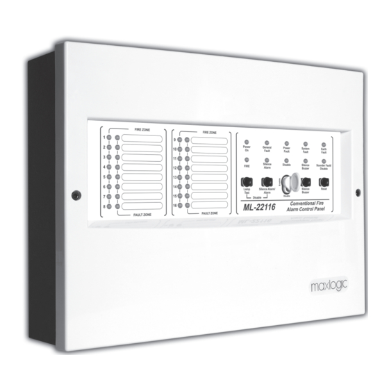
ML-22116 Front Panel Serigraphy
Diagram showing the layout of indicators, buttons, and labels on the front panel of the ML-22116 model.
Model Compliance and Documentation Information
Details compliance certifications (CPR, LVD, EMC, ROHS) and document references for each panel model.
Need help?
Do you have a question about the ML-22102 and is the answer not in the manual?
Questions and answers