Table of Contents
Advertisement
Quick Links
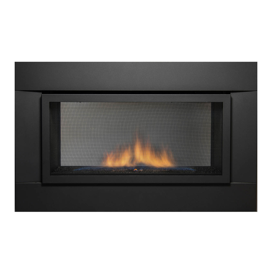
THE PALISADE
-
SEE
THU DIRECT LINEAR
20,000 BTU/h
Installation and Operating Instructions
MODELS: PALISADE-36, PALISADE-36-DELUXE
IF THE INFORMATION IN THESE INSTRUCTIONS IS
NOT FOLLOWED EXACTLY, A FIRE OR EXPLOSION
MAY RESULT CAUSING PROPERTY DAMAGE,
PERSONAL INJURY, OR DEATH.
Do not store or use gasoline or other flammable
vapors and liquids in the vicinity of this or any other
WHAT TO DO IF YOU SMELL GAS:
•
Do not try to light any appliance
•
Do not touch any electrical switch; do not use
any phone in your building
•
Immediately call your gas supplier from a
neighbour's phone. Follow gas supplier's
instructions
•
If you cannot reach your gas supplier, call the
fire department.
Installation and service must be performed by a
qualified installer, service agency or gas
supplier.
WARNING: Improper installation, adjustment,
alteration, services or maintenance can cause injury
or property damage. Refer to this manual. For
assistance or additional information consult a
qualified installer, service agency or the gas
supplier.
PLEASE READ THIS MANUAL BEFORE INSTALLING OR USING THIS APPLIANCE.
Natural Gas
CERT # LC773211
WARNING
appliance.
SAVE THIS MANUAL FOR FUTURE REFERENCE.
SEE-THROUGH – CLEAN FACE
D
UE TO HIGH TEMPERATURES
THE APPLIANCE SHOULD BE
LOCATED OUT OF TRAFFIC AND
AWAY FROM FURNITURE AND
DRAPERIES
C
HILDREN AND ADULTS SHOULD
BE ALERTED TO THE HAZARDS
OF HIGH SURFACE
TEMPERATURE AND SHOULD
STAY AWAY TO AVOID BURNS OR
CLOTHING IGNITION
Y
OUNG CHILDREN SHOULD BE
SUPERVISED WHEN THEY ARE IN
THE SAME ROOM AS THE
APPLIANCE
C
LOTHING OR OTHER
FLAMMABLE MATERIAL SHOULD
NOT BE PLACED ON OR NEAR THE
APPLIANCE
KEEP THE ROOM AREA CLEAR AND
FREE FROM COMBUSTIBLE
,
MATERIALS
GASOLINE
OTHER FLAMMABLE VAPORS AND
.
LIQUIDS
,
.
.
.
.
,
AND
Page 1 of 56
Advertisement
Table of Contents

Related Manuals for Sierra Flame PALISADE-36


Summary of Contents for Sierra Flame PALISADE-36
-
Page 1: Natural Gas
THE PALISADE THU DIRECT LINEAR 20,000 BTU/h Natural Gas Installation and Operating Instructions MODELS: PALISADE-36, PALISADE-36-DELUXE SEE-THROUGH – CLEAN FACE CERT # LC773211 UE TO HIGH TEMPERATURES WARNING THE APPLIANCE SHOULD BE IF THE INFORMATION IN THESE INSTRUCTIONS IS LOCATED OUT OF TRAFFIC AND... - Page 2 THE PALISADE THU DIRECT LINEAR 20,000 BTU/h AU GAZ NATUREL Manuel D’installation et Guide de l’utilisateur MODELS: PALISADE-36, PALISADE-36-DELUXE N RAISON DE TEMPERATURES AVERTISSEMENT ELEVEES APPAREIL DOIT ETRE ASSUREZ-VOUS DE BIEN SUIVRE LES INSTRUCTIONS PLACE HORS DE LA CIRCULATION DONNÉES DANS CETTE NOTICE POUR RÉDUIRE AU...
-
Page 3: Table Of Contents
Table of Contents IMPORTANT SAFETY INFORMATION …………………………………………………………….. 4 – 5 INTRODUCTION ........................Specifications, Appliance Dimensions & Installation Codes ......... 6 - 7 Features, Remote Control Functions ..............8 - 10 Intended Use ......................11 General Safety ....................11 - 12 OPERATION ........................... -
Page 4: Important Safety Information
WARNING AVERTISSEMENT appliance. l’appareil. CONSUMER: Retain this manual for future CONSOMMATEUR : Conservez cette notice reference. pour consultation ultérieure. WARNING • Read this owner’s manual carefully and completely before trying to assemble, operate or service this fireplace. Follow instructions for proper installation •... - Page 5 Do not use this appliance if any part has Ne pas utiliser cet appareil s’il a été plongé, been under water. Immediately call a meme partiellement, dans l’eau. Appeler un qualified service technician to inspect the technician qualifié pour inspecter l’appareil et appliance and to replace any part of the remplacer toute partie du système de control system and any gas control which...
-
Page 6: Introduction
1.0 INTRODUCTION 1.1 SPECIFICATIONS TABLE 1 ITEM NATURAL GAS (NG) INPUT: Hi 20,000 Btu/hr (5.861 kW) INPUT: Lo 13,000 Btu/hr (3.81 kW) MANIFOLD PRESSURE: Hi 3.5” w.c. (0.87 kPa) COLLECTEUR DE PRESSION: FORT MANIFOLD PRESSURE: Lo 1.7” w.c. (0.42 kPa) COLLECTEUR DE PRESSION: FAIBLE GAS INLET SUPPLY PRESSURE: Minimum: 5.0”... - Page 7 APPLIANCE DIMENSIONS Figure 1 INSTALLATION CODES This appliance is a Direct Vent appliance which draws all combustion air from outside the building through an intake vent pipe. Installation must conform to local codes. In the absence of local codes, installation must conform to the National Fuel Gas Code ANSI Z223.1/NFPA 54, or the current Natural Gas and Propane Installation Code CSA B149.1.
-
Page 8: Features, Remote Control Functions
1.2 FEATURES Ignition system: Standing pilot ignition system with thermopile and thermocouple flame detection and piezo igniter. Fan control * Optional * Variable speed control: For units equipped with a fan control, the knob controls the fan speed, turning the knob counter-clockwise turns it to the “Off”... - Page 9 Program Mode The Program function is controlled by the PROG/TIME button. The control may be programmed for up to two settings for weekdays and two settings for weekends. The control is preset to factory settings. When the Program Mode is activated, the unit will automatically be operating in the Thermostat Mode. The unit will turn on or off based upon room and set temperature.
- Page 10 Fan Control The unit must be ON to operate the Fan. The Fan will turn on after 5 minutes of operation. Once the Fan comes on, it can be controlled using the FAN button. Press the FAN button, and the fan icon and speed will appear on the LCD screen. Press the UP or DOWN button to control the fan speed (0-6).
-
Page 11: Intended Use
1.3 INTENDED USE / USAGE PROPOSÉ This appliance is intended to be used as a zero clearance fireplace. This unit is certified for installation in a bedroom, a bed sitting room or a bathroom where the maximum input is within 50 cubic feet per 1000 Btu/hr. In Canada all bedroom installations require the use of wall thermostats (note: thermostats are not allowed in the United States). - Page 12 IMPORTANT PLEASE READ THE FOLLOWING CAREFULLY It is normal for fireplaces fabricated of steel to give off some expansion and/or contraction noises during the start up or cool down cycle. It is not unusual for gas fireplaces to give off some odors the first time they are burned. This is due to the oils and sealants in the manufacturing process.
-
Page 13: Operation
2.0 OPERATION LIGHTING INSTRUCTIONS - for Intermittent Pilot FOR YOUR SAFETY, READ BEFORE LIGHTING WARNING: If you do not follow these instructions exactly, a fire or explosion may result causing property damage, personal injury or loss of life. This appliance is equipped with an ignition device which automatically lights the pilot. Do not try to light the pilot by hand. BEFORE LIGHTING smell all around the appliance area for gas. - Page 14 INSTRUCTIONS D'ALLUMAGE - Pilote intermittent POUR PLUS DE SÉCURITÉ, LIRE AVANT D’ALLUMER AVERTISSEMENT: Quiconque ne respecte pas à la letter les instructions dans la présente notice risqué de déclencher un incendie ou une explosion entraînant des dommages, des blessures ou la mort. Cet appareil est équipé...
- Page 15 2.1 LIGHTING INSTRUCTIONS – for Standing Pilot FOR YOUR SAFETY, READ BEFORE LIGHTING WARNING: If you do not follow these instructions exactly, a fire or explosion may result causing property damage, personal injury or loss of life. This appliance has a pilot which must be lighted by hand. When lighting the pilot, follow these instructions exactly. BEFORE LIGHTING smell all around the appliance area for gas.
- Page 16 2.1 INSTRUCTIONS D'ALLUMAGE – pour veilleuse permanente POUR VOTRE SÉCURITÉ, LIRE AVANT D'ALLUMER ATTENTION: Si vous ne suivez pas exactement ces instructions, un incendie ou une explosion entraînant des dommages matériels, des blessures ou des pertes de vie. Cet appareil a un pilote qui doit être allumée à la main. Lorsque l'éclairage, le pilote, suivez ces instructions à la lettre. AVANT L'ALLUMAGE odeur tout autour de l'appareil pour le gaz.
-
Page 17: Heat Output Adjustment
Robertshaw 9A0A68A6A 2.2 HEAT OUTPUT ADJUSTMENT The valve supplied with the appliance has a HI/LO knob to control the heat output and flame height (see valve diagram in Lighting Instructions, section 2.1 for either standing pilot or intermittent pilot). 2.3 FAN OPERATION (optional) For units equipped with a fan control knob, the knob is located in the valve control compartment and may be adjusted to the following settings: OFF: Turn the control fully counter-clockwise until the switch operates. - Page 18 Figure 2 Page 18 of 56...
-
Page 19: Installation
3.0 INSTALLATION 3.1 INSTALLATION & SAFETY NOTES / NOTES D'INSTALLATION ET DE SECURITE Read all instructions before starting installation and follow them carefully during installation to ensure maximum benefit and safety. Failure to follow these instructions will void your warranty and may present a fire hazard. -
Page 20: Minimum Clearances & Non Combustible Material Requirements
3.3.1 MINIMUM CLEARANCES / DÉGAGEMENTS 36.00 Non-combustible board. 11” x 35-3/8” 12.00 32.00 Framing Dimensions 32” (813mm) High x 39-1/2” (1003mm) Wide x 10-7/8” (276mm) Deep Non-combustible Board 11” x 35-3/8” will be supplied by manufacturer MINIMUM CLEARANCES TO COMBUSTIBLES 40”... - Page 21 4 of the above steel brackets can be 40.000” purchased seperately from the manufacturer. These brackets are to be used to allow venting to meet the minimum clearances to combustibles. 4 des supports en acier ci-dessus peut être acheté séparément par le fabricant. Ces supports doivent être utilisés pour permettre d'aération pour répondre aux distances minimales pour les...
-
Page 22: Gas Line Installation
/ off à distance ou une commande de l'interrupteur mural. Thermostats millivolts sont disponibles depuis n'importe quel revendeur agréé Sierra Flame. Chambre installations nécessitent l'utilisation d'un thermostat mural. Remarque: Les thermostats ne sont pas autorisés aux Etats-Unis. -
Page 23: Thermostat,Wall Switch Or Digital On/Off Remote
The thermostat, digital on/off remote or wall switch MUST be rated for millivolt use. Minimize splicing in all millivolt wiring & crimp all unavoidable splices. Le thermostat numérique, télécommande marche / arrêt ou l'interrupteur mural doit être évalué pour une utilisation en millivolts. Minimiser épissage dans l'ensemble du câblage millivolt &... -
Page 24: Direct Vent Information
Figure 4 3.3.4 DIRECT VENT INFORMATION / DIRECT VENT D'INFORMATION The unit must be connected to listed 2-ply aluminium venting, 4” flex vent on the exhaust side and listed 7” flex vent on the air intake side or can be used with Security Venting or Dura-Vent 4” x 6-5/8” with the use of Dura-Vent adapters part #’s 0924N3 &... - Page 25 This appliance’s venting system is room sealed or Direct Vent. This means that it does not require room air for combustion but draws air from outside the building. USE OF COUPLERS – WITH FLEX PIPE In the event of a puncture of the vent pipe or if an extension is needed couplers may be used. High temperature sealant shall be applied to the ends of the coupler and the coupler shall then be inserted into the flex vent.
- Page 26 Up to 34' (10363 mm) of vertical length Fire stop Flashing Collar Termination cap part # SV4CGV Use a ceiling fire stop when penetrating a ceiling or floor. Use a wall thimble when penetrating an inside or outside wall. Vent terminals shall not be recessed into a wall or siding. Metal-Fab Venting The minimum vent system for horizontal termination must consist of: Metal-Fab adapter Part # 4DDA directly on top of unit...
- Page 27 Horizontal/Vertical Venting Sample Chart H Max V Min H+H1+H2 Max Vertical/Horizontal Venting Sample Chart V Min H1 + H2 + H3 Max Horizontal/Vertical Venting Sample Chart H Max V + V1 Min H + H1 Max Vertical Venting Sample Chart V + V1 Min H + H1 Max Maximum length 34’(10363mm) Maximum total H offset 12’(3658mm)
- Page 28 USE OF SEALANT Sealant is required on vent system joints, except Metal-Fab Sure-Seal direct vent system joints (figure 7). On longer vent runs, especially vertical runs, sealant will ensure that the combustion air enters from outdoors, and not through the vent joints. Use high temperature sealant, available from local suppliers, on the inner pipe joint, applying the sealant around the outside of the male part of the vent.
- Page 29 Install the wall thimble, on the inside of the exterior wall, shield using wood screws. Attach the venting to the termination using sheet metal screws, for Z-Flex installations an Sierra Flame’s termination part # IMC1070A or IMC1070B shall be used and when using Dura-Vent or Security Venting a Dura-Vent termination part # P574 shall be used.
- Page 30 TOUJOURS vérifier les codes locaux avant l'installation VENTILATION. ETC DÉGAGEMENTS, peut varier d'ÉTAT (PROVINCE). CONSULT DURAVENT PARTS LIST OR SIERRA FLAME’S FIREPLACE MANUFACTURING PARTS LIST FOR PART NUMBERS. FOYER Duravent CONSULT LISTE DES PIÈCES OU COUPE METAL INCA de fabrication LISTE DES PIÈCES DE RÉFÉRENCE.
- Page 31 Termination above Roof Consult local codes for minimum vent cap height above the roof (X), vent must be a minimum of 2’ from any wall. To prevent water seepage; install the flashing with upper portion under the roofing material and the lower portion over the roofing material.
- Page 32 In accordance with the current CSA B149.1, Natural Gas and Propane Installation Code In accordance with the current ANSI Z223.1 / NFPA 54, National Fuel Gas Code † A vent shall not terminate directly above a sidewalk or paved driveway that is located between two single family dwellings and serves both dwellings ‡...
-
Page 33: Glass Installation
3.3.5 Glass Installation / Installation de verre Burn medium positions are critical to the safe and clean operation of this appliance. Never add any other material into the firebox. Use only with burn medium supplied with this unit. Burn positions moyennes sont critiques pour le fonctionnement sûr et propre de cet appareil. -
Page 34: Door Installation
3.3.6 Door Installation Fit the bottom of the door into the slot provided. Push top of door in and latch the locks at the top using the door latch tool provided with your fireplace. (Both sides installation is the same) Ajustez la partie inférieure de la porte dans la fente prévue. -
Page 35: Initial Firing
3.3.7 INITIAL FIRING When lit for the first few times, the appliance may emit an odor resulting from evaporation of paint and lubricants used in the manufacturing process. Open a door or window for ventilation. Anyone with a respiratory condition may need to leave the room during the initial firings. It is normal for the appliance to expand and contract while it heats up or cools down whether this is from a cold start or a steady-state condition where the fan has come on or off. -
Page 36: Altitude Adjustment
5/. Undo the set screw on the air shutter and adjust accordingly then retighten the set screw. / Défaire la vis de réglage sur le volet d'air et d'ajuster en conséquence, puis resserrez la vis de réglage. Set Screw Air tube and Air shutter shown removed for clarity purposes only. -
Page 37: Fan Access
input should be reduced 4% for each additional 1000 feet (305m) above sea level. For the USA, de- rate the unit from sea level according to the gas installation code. Toutes les vannes ont été pré-programmées et certifié pour l'installation à une altitude de 0 à 2000 pieds (0 –... - Page 38 2/. Remove the access panel by lifting up and out towards you. / Retirez le panneau d'accès en le soulevant et le vers vous. 3/. The fan is attached with magnets for ease of installation and can be pulled off the side wall. / Le ventilateur est fixé...
-
Page 39: Gas Valve Access
The pictures at left show the electrical box that controls the fan, the power cord attached and the strain relief connected to the box. 3.3.12 GAS VALVE ACCESSIBILITY / ACCESSIBILITÉ ROBINET DE GAZ. TURN THE MAIN GAS & POWER OFF TO FIREPLACE BEFORE COMMENCING ANY WORK ON THE FIREPLACE THIS SHOULD BE DONE BY A LICENSED, CERTIFIED GAS INSTALLER TURN LE PRINCIPAL GAZ ET MISE HORS TENSION AU FOYER AVANT DE... - Page 40 2/. Undo the screws on the valve mount brackets at either end of the valve. / Défaire les vis sur les supports de montage robinet à chaque extrémité de la vanne 3/. Carefully tilt the valve through the opening and lift out of firebox for accessibility. / Soigneusement incliner la valve à...
-
Page 41: Maintenance
4.0 MAINTENANCE 4.1 MAINTENANCE SAFETY WARNING AVERTISSEMENT TURN OFF THE GAS TO THE MAIN BURNER AND ALLOW THE HEATER TO COOL FOR UP TO 30 MINUTES BEFORE SERVICING. COUPEZ LE GAZ AU BRÛLEUR PRINCIPAL ET LAISSEZ L'APPAREIL REFROIDIR PENDANT JUSQU'À 30 MINUTES AVANT L'ENTRETIEN. Service and repair should be done by a qualified service person. -
Page 42: Valve & Pilot Replacement
4.5 VALVE AND PILOT ASSEMBLY REPLACEMENT WARNING AVERTISSEMENT THE FOLLOWING PROCEDURE IS TO BE PERFORMED BY QUALIFIED PERSONNEL ONLY TURN OFF THE GAS TO THE MAIN BURNER AND ALLOW THE HEATER TO COOL FOR UP TO 30 MINUTES BEFORE SERVICING. LA PROCÉDURE SUIVANTE EST EFFECTUER PAR DU PERSONNEL QUALIFIÉ... -
Page 43: Trouble Shooting
5.0 TROUBLE SHOOTING SYMPTOM CORRECTIVE ACTION POSSIBLE CAUSE Pilot will not light after A. No spark at electrode (weak or not heat source for pilot ignition) repeated triggering of the piezo ignition button 1. Improper ignition 1. Align the electrode with 1/8” (3mm) gap to pilot hood 2. - Page 44 A. Valve / Switches III. Main burner will not light 1. Valve control off 1. Turn to “ON” position 2. Blockage at the burner (line, 2. Check and clean orifice, or ports) 3. Defective wall switch 3. Conduct a continuity test or jumper wire thermostat test and replace if defective 4.
- Page 45 TROUBLE SHOOTING - INTERMITTENT PILOT SYMPTOM CORRECTIVE ACTION POSSIBLE CAUSE A. No spark at electrode (weak or not heat source for pilot ignition) I. Pilot will not light after repeated triggering of the remote control – intermittent pilot 1. Improper ignition 1.
- Page 46 4. Defective wiring or connections 4. Conduct a test with a jumper wire and repair as required 5. Defective Valve 5. Contact service technician III. Soot deposits 1. Air inlet blocked or restricted Clean air inlets 2. Vent system is restricted or 2.
-
Page 47: Replacement Parts
6.0 REPLACEMENT PARTS When requesting service or replacement parts for your unit, please provide model name and serial number. All parts listed below may be ordered from an authorized dealer. Description Part# Certification Door Burner IMC1057A CSA/UL Door Glass ASTM C1048 Restrictor Door Glass Gasket Pilot Assembly (Standing pilot) -
Page 48: Warranty
After the first year, Sierra Flame may, at its discretion, fully discharge all obligations with respect to this warranty by refunding to the original warranted purchaser the wholesale price of any warranted but defective parts. - Page 49 GARANTIE DU FOYER AU GAZ DE SIERRA FLAME Votre foyer au gaz Sierra Flame est garanti d'être exempt de défauts de matériaux et de fabrication pour une période de 5 ans à compter de la date d'achat. Cette garantie couvre: chambres de combustion, échangeurs de chaleur et brûleurs ainsi que des pièces en acier inoxydable contre le ternissement.
- Page 50 (s), la réparation ou le remplacement ou non de même, ne seront pas couverts par cette garantie ni ne doit Sierra Flame assumer la responsabilité de même. En outre, Sierra Flame ne sera pas responsable des dommages accessoires, indirects ou conséquents, sauf dans les cas prévus par la loi, et en aucun cas, ils dépassent le prix d'achat original.
-
Page 51: Label Information
8.0 LABEL INFORMATION Page 51 of 56... -
Page 52: Label Information
8.0 LABEL INFORMATION (continued) Sections of the venting system have not been installed. WARNING – Do not operate the appliance until all sections have been assembled and installed in accordance with the manufacturer’s instructions. Des sections du système d’évacuation n’ont pas été installées. AVERTISSEMENT - Ne pas utiliser l’appareil tant que toutes les sections n’ont pas été... -
Page 53: Appendix A (Intermittent Pilot & Valve Kit)
APPENDIX A (AMERICAN FLAME VALVE INFORMATION) Page 53 of 56... - Page 54 APPENDIX A (Continued) Page 54 of 56...
- Page 55 APPENDIX A (Continued) Special Features on the AF-4000 System The AF-4000 Module can be powered two different ways. The first is a standard 110 volt AC to 6.0 volt DC adaptor. This adapter is connected to the AF-4000 Module by connecting the two 1/4” female terminals from the adapter to the two 1/4”...
- Page 56 APPENDIX A (Continued) AF-4000 Wiring Diagram Sierra Flame 1503-7088 18th Ave., Burnaby, BC V3N 0A2 Page 56 of 56...
Need help?
Do you have a question about the PALISADE-36 and is the answer not in the manual?
Questions and answers