Table of Contents
Advertisement
Quick Links
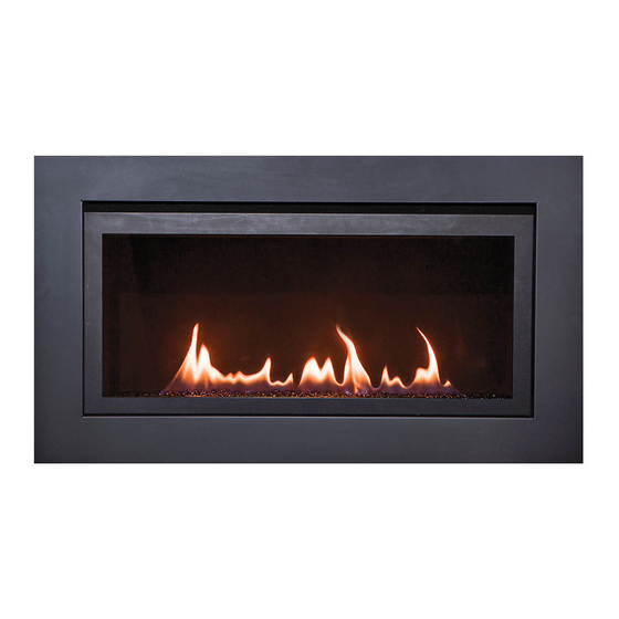
BL-936 / LANGLEY BUILDER'S LINEAR
15,500 BTU
Natural Gas & Propane
Installation and Operating Instructions
MODEL: BL-936
LANGLEY-36
IF THE INFORMATION IN THESE INSTRUCTIONS IS NOT FOLLOWED EXACTLY, A FIRE OR
EXPLOSION MAY RESULT CAUSING PROPERTY DAMAGE, PERSONAL INJURY, OR DEATH.
Do not store or use gasoline or other flammable vapors and liquids in the vicinity of this or
WHAT TO DO IF YOU SMELL GAS:
Do not try to light any appliance
Do not touch any electrical switch; do not use any phone in your building
Immediately call your gas supplier from a neighbour's phone. Follow gas supplier's
instructions
If you cannot reach your gas supplier, call the fire department.
Installation and service must be performed by a qualified installer, service agency or gas
supplier.
WARNING: Improper installation, adjustment, alteration, services or maintenance can cause
injury or property damage. Refer to this manual. For assistance or additional information
consult a qualified installer, service agency or the gas supplier.
INSTALLER: Leave this manual with the appliance.
CONSUMER: Retain this manual for future reference.
PLEASE READ THIS MANUAL BEFORE
INSTALLING OR USING THIS APPLIANCE.
SAVE THIS MANUAL FOR FUTURE
REFERENCE.
A BARRIER DESIGNED TO REDUCE THE RISK OF
BURNS FROM THE HOT VIEWING GLASS IS
PROVIDED WITH THIS APPLIANCE AND SHALL BE
INSTALLED.
CLIENT # LC773211
WARNING
any other appliance.
Page 1 of 53
Advertisement
Table of Contents

Related Manuals for Sierra Flame BL-936


Summary of Contents for Sierra Flame BL-936
- Page 1 BL-936 / LANGLEY BUILDER’S LINEAR 15,500 BTU Natural Gas & Propane Installation and Operating Instructions MODEL: BL-936 LANGLEY-36 CLIENT # LC773211 WARNING IF THE INFORMATION IN THESE INSTRUCTIONS IS NOT FOLLOWED EXACTLY, A FIRE OR EXPLOSION MAY RESULT CAUSING PROPERTY DAMAGE, PERSONAL INJURY, OR DEATH.
- Page 2 BL-936 LANGLEY LINEAR BUILDER 15,500 BTU GAZ NATUREL ET PROPANE Manuel D’installation et Guide de l’utilisateur MODEL: BL-936 / LANGLEY-36 CLIENT # LC773211 AVERTISSEMENT ASSUREZ-VOUS DE BIEN SUIVRE LES INSTRUCTIONS DONNÉES DANS CETTE NOTICE POUR RÉDUIRE AU MINIMUM LE RISQUE D'INCENDIE OU D'EXPLOSION OU POUR ÉVITER TOUT DOMMAGE MATÉRIEL, TOUTE BLESSURE OU LA MORT.
-
Page 3: Table Of Contents
Table of Contents IMPORTANT SAFETY INFORMATION …………………………………………………………….. 4 – 5 INTRODUCTION ........................Specifications, Appliance Dimensions & Installation Codes ......... 6 - 7 Features, Remote Control Functions ..............8 - 10 Intended Use ......................11 General Safety ....................11 - 12 OPERATION ........................... -
Page 4: Important Safety Information
WARNING Read this owner’s manual carefully and completely before trying to assemble, operate or service this fireplace. Follow instructions for proper installation Failure to install this appliance per the manufacturer’s instructions or failure to use only parts specifically approved with this appliance may result in property damage or personal injury. Any change to this fireplace or its controls can be dangerous. - Page 5 WARNING AVERTISSEMENT Ne pas utiliser cet appareil s’il a été plongé, Do not use this appliance if any part has meme partiellement, dans l’eau. Appeler un been under water. Immediately call a technician qualifié pour inspecter l’appareil et qualified service technician to inspect the appliance and to replace any part of the remplacer toute partie du système de control system and any gas control which...
-
Page 6: Introduction
1.0 INTRODUCTION 1.1 SPECIFICATIONS TABLE 1 ITEM NATURAL GAS PROPANE (NG) (LP) INPUT: Hi 15,500 Btu/hr (4.54 kW) 14,500 BTU/hr (4.25 kW) INPUT: Lo 11,000 Btu/hr (3.22 kW) 11,500 BTU/hr (3.37 kW) MANIFOLD PRESSURE: Hi 3.5” w.c. (0.87 kPa) 10.0” w.c. (2.49 kPa) COLLECTEUR DE PRESSION: FORT MANIFOLD PRESSURE: Lo... - Page 7 APPLIANCE DIMENSIONS 34.74” 17.37” 1.00” 0.50” 8.75” 34.20” 39.19” INSTALLATION CODES This appliance is a Direct Vent appliance which draws all combustion air from outside the building through an intake vent pipe. Installation must conform to local codes. In the absence of local codes, installation must conform to the National Fuel Gas Code ANSI Z223.1/NFPA 54, or the current Natural Gas and Propane Installation Code CSA B149.1.
-
Page 8: Features, Remote Control Functions
1.2 FEATURES Ignition system: Standing pilot ignition system with thermopile and thermocouple flame detection and piezo igniter. Gas control: * Optional* Gas control valve type: Automatic millivolt powered combination gas control valve with variable flame control for convenience and on/off switch. Optional digital remote on/off wall switch and/or optional wall thermostat (note: thermostats are not allowed in the United States). - Page 9 Press the UP or DOWN button to change the setting of P1 OFF. Press and release the SET button. Press the UP or DOWN button to change the setting of P2 ON. Press and release the SET button. Press the UP or DOWN button to change the setting of P2 OFF. Press and release the SET button. Press the UP or DOWN button to change the setting of the weekend (SS) P1 ON.
-
Page 10: Intended Use
Continuous Pilot The unit can be changed from Intermittent Pilot Ignition (IPI), to Continuous, or standing, pilot. To place the unit in continuous pilot mode, press and release the PROG/TIME and the FLAME MAIN buttons simultaneously. Continuous Pilot will appear on the LCD screen. Repeat the simultaneous PROG/TIME and FLAME MAIN push to place the unit back in IPI mode. -
Page 11: General Safety
1.4 GENERAL SAFETY / SÉCURITÉ GÉNÉRALE Maintain adequate clearances around air openings into the combustion chamber. Respecter les distances minimales convenables autour des bouches d'air dans la chambre de combustion. Maintain adequate accessibility clearances for servicing and proper operation. ... - Page 12 IMPORTANT PLEASE READ THE FOLLOWING CAREFULLY It is normal for fireplaces fabricated of steel to give off some expansion and/or contraction noises during the start up or cool down cycle. It is not unusual for gas fireplaces to give off some odors the first time they are burned. This is due to the oils and sealants in the manufacturing process.
-
Page 13: Operation
2.0 OPERATION LIGHTING INSTRUCTIONS - for Intermittent Pilot FOR YOUR SAFETY, READ BEFORE LIGHTING WARNING: If you do not follow these instructions exactly, a fire or explosion may result causing property damage, personal injury or loss of life. This appliance is equipped with an ignition device which automatically lights the pilot. Do not try to light the pilot by hand. BEFORE LIGHTING smell all around the appliance area for gas. - Page 14 INSTRUCTIONS D'ALLUMAGE - Pilote intermittent POUR PLUS DE SÉCURITÉ, LIRE AVANT D’ALLUMER AVERTISSEMENT: Quiconque ne respecte pas à la letter les instructions dans la présente notice risqué de déclencher un incendie ou une explosion entraînant des dommages, des blessures ou la mort. Cet appareil est équipé...
- Page 15 2.1 LIGHTING INSTRUCTIONS – for Standing Pilot FOR YOUR SAFETY, READ BEFORE LIGHTING WARNING: If you do not follow these instructions exactly, a fire or explosion may result causing property damage, personal injury or loss of life. This appliance has a pilot which must be lighted by hand. When lighting the pilot, follow these instructions exactly. BEFORE LIGHTING smell all around the appliance area for gas.
- Page 16 2.1 INSTRUCTIONS D'ALLUMAGE - pour veilleuse permanente POUR VOTRE SÉCURITÉ, LIRE AVANT D'ALLUMER ATTENTION: Si vous ne suivez pas exactement ces instructions, un incendie ou une explosion entraînant des dommages matériels, des blessures ou des pertes de vie. Cet appareil a un pilote qui doit être allumée à la main. Lorsque l'éclairage, le pilote, suivez ces instructions à la lettre. AVANT L'ALLUMAGE odeur tout autour de l'appareil pour le gaz.
-
Page 17: Heat Output Adjustment
Apex Control Valve 2.2 HEAT OUTPUT ADJUSTMENT The valve supplied with the appliance has a HI/LO knob to control the heat output and flame height (see valve diagram in Lighting Instructions, section 2.1). 3.0 INSTALLATION 3.1 INSTALLATION & SAFETY NOTES / NOTES D'INSTALLATION ET DE SECURITE Read all instructions before starting installation and follow them carefully during installation to ensure maximum benefit and safety. -
Page 18: Unpacking
3.2 UNPACKING Please check the appliance carefully for any damaged or missing components (specifically check the glass condition). Report any problems to your dealer within 30 days of purchase. 3.3 INSTALLATION For satisfactory results it is necessary to plan certain aspects of the installation prior to the appliance’s final positioning. -
Page 19: Installing Non Combustible Board
3.3.1 INSTALLING NON-COMBUSTIBLE BOARD WARNING THE SURFACE ABOVE THE APPLIANCE GETS VERY HOT. IF PROPER FINISHING MATERIALS ARE NOT USED, CRACKING CAN OCCUR. LA SURFACE AU-DESSUS DE L'APPAREIL EST TRÈS CHAUDE. SI DES MATERIAUX DE FINITION CORRESPONDANTS NE SONT PAS UTILISES, DES RISQUES PEUVENT SURVENIR. -
Page 20: Minimum Clearances & Non Combustible Material Requirements
3.3.2 MINIMUM CLEARANCES / DÉGAGEMENTS NON- COMBUSTIBLE BOARD 9.5” X 36” SUPPLIED BY 36.00” MANUFACTURER 12.00” Heat baffle must be MANUFACTURER fixed to non- NOTES combustible board on PREVIOUS PAGE installation. (see diagram on page 18. 1.00” 1.00” 6.00” A = 40” TO INTERNAL CEILING B = 1”... -
Page 21: Gas Line Installation
When using paint or lacquer to finish the mantel, such paint or lacquer must be heat resistant ( up to 250 F ) to prevent discolorations. Lors de l'utilisation de peinture ou de laque à la fin de la cheminée, de peinture ou laque doit être résistante à... -
Page 22: Thermostat,Wall Switch Or Digital On/Off Remote
3.3.4 THERMOSTAT, WALL SWITCH OR DIGITAL ON/OFF REMOTE INSTALLATION The burner control knob is located in the control compartment at the bottom of the unit. For your convenience, the unit can also be operated by a thermostat, a digital on/off remote or a wall switch control. Millivolt thermostats are available from any authorized Inca Metal Cutting dealer. -
Page 23: Direct Vent Information
After the unit is installed and the gas line hooked up, crimp a fork connector to each wire and attach them to the TH/TP and TH screws located on the valve. Après que l'unité est installée et la conduite de gaz accroché, sertir un connecteur fourchette pour chaque fil et les joindre à... - Page 24 If at any time the vent-air intake piping is dismantled, use the vent manufacturer’s instructions and the sealing instructions for reassembly. Si à tout moment de la tuyauterie d'admission d'air de ventilation est démontée, utilisez la ventilation instructions du fabricant et les instructions d'étanchéité pour le remontage Figure 5 This appliance’s venting system is room sealed or Direct Vent.
- Page 25 2-Ply Aluminum Flex Vent The minimum vent system for horizontal termination must consist of: 2” (50.8 mm) vertical length (measured to center of vent pipe) with a 45 degree bend and a 9.5” (241 mm) horizontal length (measured from center of vent pipe) Wall thimble part# B92 Horizontal termination cap part # 1393 The maximum horizontal vent system consists of:...
- Page 26 USE OF SEALANT Sealant is required on vent system joints, (figure 7). On longer vent runs, especially vertical runs, sealant will ensure that the combustion air enters from outdoors, and not through the vent joints. Use high temperature sealant, available from local suppliers, on the inner pipe joint, applying the sealant around the outside of the male part of the vent.
- Page 27 Horizontal Wall Vent Terminations The position of the horizontal vent termination must be positioned in such a way as to meet all local building codes. Attach the correct length of pipe. Mark the center line of the pipe facing the wall (allowing for a 1/4” rise per foot of horizontal, example 10 ft of horizontal would require a rise of 2.5”).
- Page 28 Safety Cage / Cage de sécurité A safety cage may be required on low terminations. Please check with your local safety authority. Une cage de sécurité peut être nécessaire de faibles terminaisons. S'il vous plaît vérifiez auprès de votre autorité de sécurité locale. Vertical Installations Always maintain a 1”...
- Page 29 In accordance with the current CSA B149.1, Natural Gas and Propane Installation Code In accordance with the current ANSI Z223.1 / NFPA 54, National Fuel Gas Code † A vent shall not terminate directly above a sidewalk or paved driveway that is located between two single family dwellings and serves both dwellings ‡...
-
Page 30: Glass Media Installation
3.3.6 GLASS INSTALLATION / VERRE D'INSTALLATION Step 1. Sprinkle burner channel with glass../ Canal du brûleur Saupoudrer de verre. Step 2 Install the door see instructions below. Make sure to cover the burner pan evenly / Installez la porte voir les instructions ci-dessous. Assurez-vous de couvrir la casserole du brûleur régulièrement Turn your fireplace on and wait approximately 10-15 minutes until the flames are a nice yellow colour. - Page 31 BOTTOM DOOR CHANNEL BOTTOM DOOR CHANNEL When closed properly the door latch will hook over the top of the door bracket and seal the door onto the fireplace. / Quand il est fermé correctement le loquet se brancher sur le dessus du support de porte et sceller la porte sur la cheminée.
- Page 32 If the glass has been damaged or broken it is highly recommended that you contact a qualified service person. Remove the broken pieces (be sure to wear gloves) and remove door. See the replacement parts list, at the end of the manual, you will require one 5 mm ceramic glass panel with gasket installed.
-
Page 33: Initial Firing
3.3.8 INITIAL FIRING When lit for the first few times, the appliance may emit an odor resulting from evaporation of paint and lubricants used in the manufacturing process. Open a door or window for ventilation. Anyone with a respiratory condition may need to leave the room during the initial firings. It is normal for the appliance to expand and contract while it heats up or cools down whether this is from a cold start or a steady-state condition where the fan has come on or off. -
Page 34: Altitude Adjustment
5/. Undo the set screw on the air shutter and adjust accordingly then retighten the set screw. / Défaire la vis de réglage sur le volet d'air et d'ajuster en conséquence, puis resserrez la vis de réglage. Set Screw Air tube and Air shutter shown removed for clarity purposes only. -
Page 35: Optional Fan Accessibility
3.3.12 OPTIONAL FAN ACCESSIBILITY / FAN ACCESSIBILITÉ TURN THE MAIN GAS & POWER OFF TO FIREPLACE BEFORE COMMENCING ANY WORK ON THE FIREPLACE THIS SHOULD BE DONE BY A LICENSED, CERTIFIED GAS INSTALLER TURN LE PRINCIPAL GAZ ET MISE HORS TENSION AU FOYER AVANT DE COMMENCER TOUT TRAVAIL SUR LA FOYER CELA DEVRAIT ETRE FAIT PAR UNE LICENCE, VOTRE FOURNISSEUR DE 1/. -
Page 36: Gas Valve Access
3.3.13 GAS VALVE ACCESSIBILITY / ACCESSIBILITÉ ROBINET DE GAZ. TURN THE MAIN GAS & POWER OFF TO FIREPLACE BEFORE COMMENCING ANY WORK ON THE FIREPLACE THIS SHOULD BE DONE BY A LICENSED, CERTIFIED GAS INSTALLER TURN LE PRINCIPAL GAZ ET MISE HORS TENSION AU FOYER AVANT DE COMMENCER TOUT TRAVAIL SUR LA FOYER CELA DEVRAIT ETRE FAIT PAR UNE LICENCE, VOTRE FOURNISSEUR DE GAZ. -
Page 37: Maintenance
4.0 MAINTENANCE 4.1 MAINTENANCE SAFETY / SÉCURITÉ ENTRETIEN WARNING AVERTISSEMENT TURN OFF THE GAS TO THE MAIN BURNER AND ALLOW THE HEATER TO COOL FOR UP TO 30 MINUTES BEFORE SERVICING. COUPEZ LE GAZ AU BRÛLEUR PRINCIPAL ET LAISSEZ L'APPAREIL REFROIDIR PENDANT JUSQU'À... -
Page 38: Glass Cleaning
4.3 GLASS CLEANING / NETTOYAGE DE LA VITRE The inside of the glass may require periodic cleaning to remove deposits left from impurities in the gas and combustion air. For best results, use a ceramic glass cleaner or polish. Use a cleaner suitable for ceramic glass (e.g. - Page 39 4. Disconnect the gas line to the appliance and disconnect the gas line from the valve to the main orifice. / Débrancher la conduite de gaz à l'appareil et débranchez la conduite de gaz de la vanne à l'orifice principal. 5.
-
Page 40: Trouble Shooting
5.0 TROUBLE SHOOTING SYMPTOM CORRECTIVE ACTION POSSIBLE CAUSE Pilot will not light after A. No spark at electrode (weak or not heat source for pilot ignition) repeated triggering of the piezo ignition button 1. Align the electrode with 1/8” (3mm) gap 1. - Page 41 A. Valve / Switches III. Main burner will not light 1. Turn to “ON” position 1. Valve control off 2. Blockage at the burner (line, 2. Check and clean orifice, or ports) 3. Defective wall switch 3. Conduct a continuity test or jumper wire thermostat test and replace if defective 4.
- Page 42 TROUBLE SHOOTING - INTERMITTENT PILOT SYMPTOM CORRECTIVE ACTION POSSIBLE CAUSE A. No spark at electrode (weak or not heat source for pilot ignition) I. Pilot will not light after repeated triggering of the remote control – intermittent pilot 1. Align the electrode with 1/8” (3mm) gap to 1.
- Page 43 4. Defective wiring or connections 4. Conduct a test with a jumper wire and repair as required 5. Defective Valve 5. Contact service technician III. Soot deposits 1. Air inlet blocked or restricted Clean air inlets 2. Vent system is restricted or 2.
-
Page 44: Replacement Parts
6.0 REPLACEMENT PARTS When requesting service or replacement parts for your unit, please provide model name and serial number. All parts listed below may be ordered from an authorized dealer. Description Part# Certification Door 1305 Burner 1397 Door Glass 1326 ASTM C1048 Restrictor 1333... -
Page 45: Warranty
After the first year, Inca Metal Cutting / Sierra Flame may, at its discretion, fully discharge all obligations with respect to this warranty by refunding to the original warranted purchaser the wholesale price of any warranted but defective parts. - Page 46 Inca Metal Cutting / Sierra Flame neither assumes, nor authorizes any third party to assume, on its behalf, any other liabilities with respect to the sale of this product. Inca Metal Cutting / Sierra Flame will not be responsible for: over firing, downdrafts, spillage caused by environmental conditions such as rooftops, buildings, nearby...
- Page 47 Cette garantie définit les obligations et la responsabilité de l'Inca Metal Cutting / Sierra Flame à l'égard de l'Inca Metal Cutting / Sierra Flame foyer au gaz et toute autre garantie expresse ou implicite à l'égard de ce produit, ses composants ou accessoires est exclue.
-
Page 48: Label Information
8.0 LABEL INFORMATION Page 48 of 53... - Page 49 8.0 LABEL INFORMATION (continued) WARNING Electrical Grounding Instructions This appliance is equipped with a three prong (grounding) plug for your protection against shock hazard and should be plugged directly into a properly grounded three prong receptacle. Do not cut or remove the grounding prong from this plug.
-
Page 50: Appendix A (Intermittent Pilot & Valve Kit)
APPENDIX A (AMERICAN FLAME VALVE INFORMATION) Page 50 of 53... - Page 51 APPENDIX A (Continued) Page 51 of 53...
- Page 52 APPENDIX A (Continued) Special Features on the AF-4000 System The AF-4000 Module can be powered two different ways. The first is a standard 110 volt AC to 6.0 volt DC adaptor. This adapter is connected to the AF-4000 Module by connecting the two 1/4” female terminals from the adapter to the two 1/4”...
- Page 53 APPENDIX A (Continued) AF-4000 Wiring Diagram Inca Metal Cutting Ltd Unit 100 – 11091 Bridgeport Road Richmond, BC V6X 1T3 Canada Sierra Flame 502 – 1027 Davie Street Vancouver, BC V6E 4L2 Canada Page 53 of 53...
Need help?
Do you have a question about the BL-936 and is the answer not in the manual?
Questions and answers