Page 2
Reproduction in any manner whatsoever without the written permission of D-Link Corporation is strictly forbidden. Trademarks used in this text: D-Link and the D-Link logo are trademarks of D-Link Corporation; Microsoft and Windows are registered trademarks of Microsoft Corporation. Other trademarks and trade names may be used in this document to refer to either the entities claiming the marks and names or their products.
The documents below are a further source of information in regards to configuring and troubleshooting the switch. All the documents are available either from the CD, bundled with this switch, or from the D-Link website. Other documents related to this switch are: •...
D-Link DGS-1100 Series Switch User Manual Notes, Notices, and Cautions Below are examples of the three types of indicators used in this manual. When administering your switch using the information in this document, you should pay special attention to these indicators.
D-Link DGS-1100 Series Switch User Manual Product Introduction Thank you and congratulations on your purchase of D-Link DGS-1100 Series Switch Products. D-Link's next generation DGS-1100 Series switches blends plug-and-play simplicity with exceptional value and reliability for small and medium-sized business (SMB) networking. All models are housed in a new style rack-mount metal case with easy-to-view front panel diagnostic LEDs.
D-Link DGS-1100 Series Switch User Manual DGS-1100-18 16-Port 10/100/1000Mpbs + 2 Port SFP 1000 Mbps Switch Front Panel Figure 2-3 - DGS-1100-18 Front Panel Power LED: The Power LED lights up when the Switch is connected to a power source.
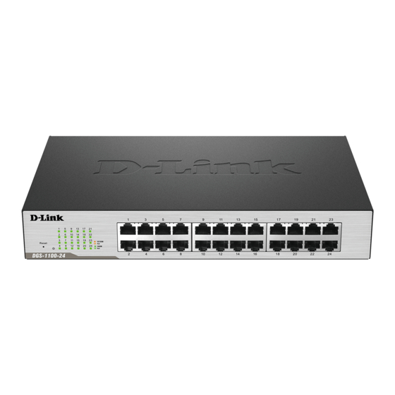
D-Link DGS-1100 Series Switch User Manual DGS-1100-24 24-Port 10/100/1000Mpbs Switch Front Panel Figure 2-5 – DGS-1100-24 Front Panel Power LED: The Power LED lights up when the Switch is connected to a power source. Link/Act/Speed LED (Ports 1-24): Solid Green: When there is a secure 1000Mbps connection at the port.
D-Link DGS-1100 Series Switch User Manual DGS-1100-24P 24-Port 10/100/1000Mpbs PoE Switch Front Panel Figure 2-7 – DGS-1100-24P Front Panel Power LED: The Power LED lights up when the Switch is connected to a power source. Link/Act/Speed LED (Ports 1-24): Solid Green: When there is a secure 1000Mbps connection at the port.
D-Link DGS-1100 Series Switch User Manual DGS-1100-26 24-Port 10/100/1000Mpbs + 2 Port SFP 1000 Mbps Switch Front Panel Figure 2-9 – DGS-1100-26 Front Panel Power LED: The Power LED lights up when the Switch is connected to a power source.
D-Link DGS-1100 Series Switch User Manual Hardware Installation This chapter provides unpacking and installation information for the D-Link Switch. Step 1: Unpacking Open the shipping carton and carefully unpack its contents. Please consult the packing list located in the User Manual to make sure all items are present and undamaged. If any item is missing or damaged, please contact your local D-Link reseller for replacement.
D-Link DGS-1100 Series Switch User Manual Rack Installation The switch can be mounted in an EIA standard size 11-inch rack, which can be placed in a wiring closet with other equipment. To install, attach the mounting brackets to the switch’s side panels (one on each side) and secure them with the screws provided (please note that these brackets are not designed for palm size switches).
D-Link DGS-1100 Series Switch User Manual Step 3 – Plugging in the AC Power Cord Users may now connect the AC power cord into the rear of the switch and to an electrical outlet (preferably one that is grounded and surge protected).
Page 17
D-Link DGS-1100 Series Switch User Manual Figure 3-5 – Ground cable, screw and #8 terminal lug rings...
D-Link Network Assistant DNA (D-Link Network Assistant) included on the installation CD is a program for discovering DGS- 1100 Series Switches with the same L2 network segment connected to your PC. This tool can support windows 2000, XP, Vista, and Windows 7.
D-Link DGS-1100 Series Switch User Manual Logging onto the Web Manager To access the Web User Interface, simply open a standard web browser on the management PC and enter the Switch’s default IP address into the address bar of the browser and press the Enter key.
D-Link DGS-1100 Series Switch User Manual Smart Wizard After a successfully connecting to the Web User Interface for the first time, the Smart Wizard embedded Web utility will be launched. This wizard will guide the user through basic configuration steps that is essential for first time connection to the Switch.
Page 21
D-Link DGS-1100 Series Switch User Manual Tick the Ignore the wizard next time option to skip the Smart Wizard on the next login. Click the Exit button to discard the changes made, exit the Smart Wizard, and continue to the Web Click the Next button to accept the changes made and continue to the next step.
Page 22
D-Link DGS-1100 Series Switch User Manual Step 3 – SNMP Settings In this window, the user can enable or disable the SNMP function. Figure 4-6 SNMP window The fields that can be configured are described below: Parameter Description SNMP Select the Enabled option to enable the SNMP function.
D-Link DGS-1100 Series Switch User Manual Web User Interface (Web UI) By clicking the Exit button in the Smart Wizard, you will enter the Web-based Management interface. Areas of the User Interface The figure below shows the user interface. Three distinct areas that divide the user interface, as described in the table.
D-Link DGS-1100 Series Switch User Manual System Device Information System Information Setting IPv4 Interface IPv6 Interface PoE (DGS-1100-24P Only) System Log Time Time Profile Device Information In this window, the Device Information, CPU, and Used status are displayed. It appears automatically when you log in the Switch.
D-Link DGS-1100 Series Switch User Manual System Information Settings The user can enter a System Name, System Location, and System Contact to aid in defining the Switch. To view the following window, click System > System Information Settings, as shown below:...
D-Link DGS-1100 Series Switch User Manual Mask If Static is selected, enter the IP address of the switch. If DHCP or BOOTP is selected, the automatically obtained network mask will be displayed. Gateway If Static is selected, enter the IP address of the switch. If DHCP or BOOTP is selected, the automatically obtained gateway will be displayed.
D-Link DGS-1100 Series Switch User Manual The fields that can be configured are described below: Parameter Description From Port / To Port Select the appropriate port range used for the configuration here. State Select this option to enable or disable the physical port here.
Page 28
D-Link DGS-1100 Series Switch User Manual Figure 5-6 Jumbo Frame window The fields that can be configured are described below: Parameter Description From Port / To Port Select the appropriate port range used for the configuration here. Jumbo Frame Enable Select whether to Enable or Disable support for Jumbo Frames on the switch.
Powered Devices (PDs) over Category 5 or Category 3 UTP Ethernet cables. The Switch follows the standard PSE (Power Sourcing Equipment) pinout Alternative A, whereby power is sent out over pins 1, 2, 3 and 6. The Switches work with all D-Link 802.3af capable devices. The Switch includes the following PoE features: •...
D-Link DGS-1100 Series Switch User Manual The fields that can be configured are described below: Parameter Description Usage Threshold Enter the usage threshold to generate a log and send the corresponding standard notification. Trap State Select this option to enable or disable the sending of PoE notifications.
D-Link DGS-1100 Series Switch User Manual PoE Configuration This window is used to configure the PoE port. To view the following window, click System > PoE > PoE Configuration, as shown below: Figure 5-9 PoE Configuration window The fields that can be configured are described below:...
D-Link DGS-1100 Series Switch User Manual System Log System Log Settings This window is used to view and configure the system’s log settings. To view the following window, click System > System Log > System Log Settings, as shown below:...
D-Link DGS-1100 Series Switch User Manual The fields that can be configured are described below: Parameter Description Host IPv4 Address Enter the system log server’s IPv4 address here. UDP Port Enter the system log server’s UDP port number here. This value must be between 1024 and 65535.
D-Link DGS-1100 Series Switch User Manual Time The Simple Network Time Protocol (SNTP) is a protocol for synchronizing computer clocks through the Internet. It provides comprehensive mechanisms to access national time and frequency dissemination services, organize the SNTP subnet of servers and clients, and adjust the system clock in each participant.
D-Link DGS-1100 Series Switch User Manual Parameter Description Summer Time State Select the summer time setting. Options to choose from are Disabled, and Date Setting. Disabled - Select to disable the summer time setting. Date Setting - Select to configure the summer time that should start and end on the specified date.
D-Link DGS-1100 Series Switch User Manual The fields that can be configured for SNTP Server Setting are described below: Parameter Description IPv4 Address Enter the IP address of the SNTP server which provides the clock synchronization. Click the Apply button to add the SNTP server.
D-Link DGS-1100 Series Switch User Manual Management User Account Settings SNMP HTTP/HTTPS D-Link Discovery Protocol User Account Settings This window is used to configure the user accounts. The active user account sessions can be viewed. There are several configuration options available in the Web User Interface (Web UI). The set of configuration options available to the user depends on the account’s Privilege Level.
D-Link DGS-1100 Series Switch User Manual SNMP Simple Network Management Protocol (SNMP) is an OSI Layer 7 (Application Layer) designed specifically for managing and monitoring network devices. SNMP enables network management stations to read and modify the settings of gateways, routers, switches, and other network devices.
D-Link DGS-1100 Series Switch User Manual SNMP Global Settings This window is used to configure the SNMP global settings and trap settings. To view the following window, click Management > SNMP > SNMP Global Settings, as shown below: Figure 6-2 SNMP Global Settings window...
D-Link DGS-1100 Series Switch User Manual Figure 6-3 SNMP Community Table Settings window The fields that can be configured are described below: Parameter Description Access Right Select the access right here. Options to choose from are Read Only, and Read Write.
D-Link Discovery Protocol This window is used to configure and display D-Link Discovery Protocol (DDP). To view the following window, click Management > D-Link Discovery Protocol, as shown below: Figure 6-6 D-Link Discovery Protocol window The fields that can be configured for D-Link Discovery Protocol are described below:...
D-Link DGS-1100 Series Switch User Manual Layer 2 Features VLAN Spanning Tree Loopback Detection Link Aggregation L2 Multicast Control LLDP Static FDB Unicast Static FDB This window is used to view and configure the static unicast forwarding settings on the Switch.
D-Link DGS-1100 Series Switch User Manual Multicast Static FDB This window is used to view and configure the multicast static FDB settings. To view the following window, click L2 Features > FDB > Static FDB > Multicast Static FDB, as shown below:...
D-Link DGS-1100 Series Switch User Manual Figure 7-4 MAC Address Table Settings (MAC Address Learning) window The fields that can be configured are described below: Parameter Description From Port / To Port Select the range of ports that will be used for this configuration here.
D-Link DGS-1100 Series Switch User Manual VLAN 802.1Q VLAN This window is used to view and configure the VLAN settings on this switch. To view the following window, click L2 Features > VLAN > 802.1Q VLAN, as shown below: Figure 7-6 802.1Q VLAN window The fields that can be configured for 802.1Q VLAN are described below:...
D-Link DGS-1100 Series Switch User Manual Click the Apply button to accept the changes made. Click the Delete All button to delete all the entries found in the display table. Management VLAN This window is used to configure the asymmetric VLAN function.
Page 47
D-Link DGS-1100 Series Switch User Manual Click the View Detail button to view more detailed information about the VLAN on the specific interface. Click the Edit button to re-configure the specific entry. After clicking the VLAN Detail button, the following page will appear.
Page 48
D-Link DGS-1100 Series Switch User Manual Click the Back button to return to the previous window. When Hybrid was selected as the VLAN Mode, the following page will appear. Figure 7-13 Configure VLAN Interface - Hybrid window The fields that can be configured are described below:...
D-Link DGS-1100 Series Switch User Manual Parameter Description VLAN Mode Select the VLAN mode option here. Options to choose from are Access, Hybrid, and Trunk. Acceptable Frame Select the acceptable frame behavior option here. Options to choose from are Tagged Only, Untagged Only, and Admit All.
Page 50
D-Link DGS-1100 Series Switch User Manual MAC Settings and Surveillance Device This window is used to configure the user-defined surveillance device OUI and display the surveillance VLAN information. To view the following window, click L2 Features > VLAN > Auto Surveillance VLAN > MAC...
D-Link DGS-1100 Series Switch User Manual Voice VLAN Voice VLAN Global Voice VLAN is a VLAN used to carry voice traffic from IP phone. Because the sound quality of an IP phone call will be deteriorated if the data is unevenly sent, the quality of service (QoS) for voice traffic shall be configured to ensure the transmission priority of voice packet is higher than normal traffic.
Page 52
D-Link DGS-1100 Series Switch User Manual Voice VLAN Port This window is used to configure the user-defined voice traffic’s port. To view the following window, click L2 Features > VLAN > Voice VLAN > Voice VLAN OUI, as show below:...
D-Link DGS-1100 Series Switch User Manual Voice VLAN OUI This window is used to configure the user-defined voice traffic’s OUI. The OUI is used to identify the voice traffic. There are a number of pre-defined OUIs. The user can further define the user-defined OUIs if needed.
D-Link DGS-1100 Series Switch User Manual Spanning Tree This Switch supports two versions of the Spanning Tree Protocol: 802.1D-1998 STP, 802.1D-2004 Rapid STP. 802.1D-1998 STP will be familiar to most networking professionals. However, since 802.1D-2004 RSTP has been recently introduced to DGS-1100 switches, a brief introduction to the technology is provided below followed by a description of how to set up 802.1D-1998 STP, 802.1D-...
D-Link DGS-1100 Series Switch User Manual STP Global Settings This window is used to view and configure the STP global settings. To view the following window, click L2 Features > Spanning Tree > STP Global Settings, as shown below: Figure 7-212 STP Global Settings window...
D-Link DGS-1100 Series Switch User Manual Figure 7-223 STP Port Settings window The fields that can be configured are described below: Parameter Description From Port / To Port Select the appropriate port range used for the configuration here. Port Fast Select the port fast option here.
Page 57
D-Link DGS-1100 Series Switch User Manual The fields that can be configured for Loopback Detection Global Settings are described below: Parameter Description Loopback Detection Select to enable or disable loopback detection. The default is Disabled. Time Interval Set a Loop detection Interval between 1 and 32767 seconds.
D-Link DGS-1100 Series Switch User Manual Link Aggregation Understanding Port Trunk Groups Port trunk groups are used to combine a number of ports together to make a single high-bandwidth data pipeline. Figure 7-245 Example of Port Trunk Group The Switch treats all ports in a trunk group as a single port. Data transmitted to a specific host (destination address) will always be transmitted over the same port in a trunk group.
Page 59
D-Link DGS-1100 Series Switch User Manual The Spanning Tree Protocol will treat a link aggregation group as a single link, on the switch level. On the port level, the STP will use the port parameters of the Master Port in the calculation of port cost and in determining the state of the link aggregation group.
Page 60
D-Link DGS-1100 Series Switch User Manual After clicking the Channel Detail button, the following page will be available. Figure 7-267 Port Channel window Click the Back button to return to the previous window.
D-Link DGS-1100 Series Switch User Manual L2 Multicast Control IGMP Snooping Internet Group Management Protocol (IGMP) snooping allows the Switch to recognize IGMP queries and reports sent between network stations or devices and an IGMP host. IGMP Snooping Settings To view the following window, click L2 Features > L2 Multicast Control > IGMP Snooping > IGMP...
Page 62
D-Link DGS-1100 Series Switch User Manual IGMP Snooping Groups Settings This window is used to configure and view the IGMP snooping static group, and view IGMP snooping group. To view the following window, click L2 Features > L2 Multicast Control > IGMP Snooping > IGMP...
D-Link DGS-1100 Series Switch User Manual Multicast Filtering This window is used to view and configure the Layer 2 multicast filtering settings. To view the following window, click L2 Features > L2 Multicast Control > Multicast Filtering, as shown below:...
D-Link DGS-1100 Series Switch User Manual LLDP LLDP Global Settings LLDP (Link Layer Discovery Protocol) provides IEEE 802.1AB standards-based method for switches to advertise themselves to neighbor devices, as well as to learn about neighbor LLDP devices. This window is used to configure the LLDP global settings.
D-Link DGS-1100 Series Switch User Manual Quality of Service (QoS) 802.1p Priority Port Rate Limiting 802.1p Priority This window is used to view and configure the port’s default CoS settings. To view the following window, click QoS > 802.1p Priority, as shown below:...
D-Link DGS-1100 Series Switch User Manual Port Rate Limiting This window is used to view and configure the port rate limiting settings. To view the following window, click QoS > Port Rate Limiting, as shown below: Figure 8-2 Port Rate Limiting window...
Zone Defense Settings Safeguard Engine D-Link’s Safeguard Engine is a robust and innovative technology that automatically throttles the impact of packet flooding into the switch's CPU. This function helps protect the Smart Switch from being interrupted by malicious viruses or worm attacks.
D-Link DGS-1100 Series Switch User Manual Traffic Segmentation Settings This window is used to view and configure the traffic segmentation settings. When the traffic segmentation forwarding domain is specified, packets received by the port will be restricted in Layer 2 packet forwarding to interfaces within the domain. When the forwarding domain of a port is empty, Layer 2 forwarding for packets received by the port is not restricted.
D-Link DGS-1100 Series Switch User Manual Storm Control This window is used to view and configure the storm control settings. Once a packet storm has been detected, the Switch will drop packets coming into the Switch until the storm has subsided.
D-Link DGS-1100 Series Switch User Manual To view the following window, click Security > DoS Attack Prevention Settings, as shown below: Figure 9-4 DoS Attack Prevention Settings window The fields that can be configured for DoS Attack Prevention Settings are described below:...
D-Link DGS-1100 Series Switch User Manual Secure Sockets Layer (SSL) is a security feature that will provide a secure communication path between a host and client through the use of authentication, digital signatures and encryption. SSL Global Settings This window is used to view and configure the SSL feature’s global settings.
D-Link DGS-1100 Series Switch User Manual 10. OAM Cable Diagnostics Cable Diagnostics The cable diagnostics feature is designed primarily for administrators or customer service representatives to verify and test copper cables; it can rapidly determine the quality of the cables and the types of error.
D-Link DGS-1100 Series Switch User Manual 11. Monitoring Statistics Mirror Settings Statistics Port Counters This window is used to display port counter statistics. To view the following window, click Monitoring > Statistics > Port Counters, as show below: Figure 11-1 Port Counters window...
D-Link DGS-1100 Series Switch User Manual Mirror Settings This window is used to view and configure the mirror feature’s settings. The Switch allows users to copy frames transmitted and received on a port and redirect the copies to another port. Attach a monitoring device to the mirroring port, such as a sniffer, to view details about the packets passing through the first port.
D-Link DGS-1100 Series Switch User Manual 12. Green Power Saving Power Saving This window is used to configure the power saving settings of the Switch. To view the following window, click Green > Power Saving, as shown below: Figure 12-1 Power Saving window...
Page 76
D-Link DGS-1100 Series Switch User Manual Figure 12-2 Power Saving Shutdown Settings window The fields that can be configured are described below: Parameter Description From Port / To Port Select the appropriate port range used for the configuration here. Time Range If a Time Profile was previously created, select the desired profile from the drop down list.
D-Link DGS-1100 Series Switch User Manual Energy Efficient Ethernet (EEE) is defined in IEEE 802.3az. It is designed to reduce the energy consumption of a link when no packets are being sent. To view the following window, click Green > EEE, as shown below:...
D-Link DGS-1100 Series Switch User Manual 13. Save and Tools Save Configuration Firmware Upgrade & Backup Configuration Restore & Backup Log Backup Ping Reset Reboot System Save Configuration This window is used to save the running configuration to the start-up configuration of the Switch.
D-Link DGS-1100 Series Switch User Manual Firmware Upgrade from HTTP This window is used to initiate a firmware upgrade from a local PC using HTTP. To view the following window, click Tools > Firmware Upgrade & Backup > Firmware Upgrade...
D-Link DGS-1100 Series Switch User Manual Figure 13-5 Firmware Backup to HTTP window The fields that can be configured are described below: Parameter Description Source Select the source image to use for the firmware backup. Click the Backup button to initiate the firmware backup.
D-Link DGS-1100 Series Switch User Manual Configuration Restore & Backup Configuration Restore from HTTP This window is used to initiate a configuration restore from a local PC using HTTP. Note: If the switch is in HTTPS mode, the firmware or configuration cannot be upgraded using regular HTTP.
D-Link DGS-1100 Series Switch User Manual Click the Restore button to initiate the configuration restore. Click Effective immediately (running-config) to have the uploaded configuration loaded immediately. Click Take effect after the next boot (startup-config) to load the configuration after the switch has been rebooted.
D-Link DGS-1100 Series Switch User Manual Log Backup Log Backup to HTTP This window is used to initiate a system log backup to a local PC using HTTP. To view the following window, click Tools > Log Backup > Log Backup to HTTP, as shown below: Figure 13-11 Log Backup to HTTP window Click the Backup button to initiate the system log backup.
D-Link DGS-1100 Series Switch User Manual Ping Ping is a small program that sends ICMP Echo packets to the IP address you specify. The destination node then responds to or “echoes” the packets sent from the Switch. This is very useful to verify connectivity between the Switch and other nodes on the network.
D-Link DGS-1100 Series Switch User Manual Figure 13-15 Reset window Select the The Switch will be reset to its factory defaults including IP address and stacking information, and the will save, reboot option to reset the Switch’s configuration to its factory default settings.
D-Link DGS-1100 Series Switch User Manual 14. Appendix A - Ethernet Technology This chapter will describe the features of the D-Link DGS-1100 Series Switch and provide some background information about Ethernet/Fast Ethernet/Gigabit Ethernet switching technology. Gigabit Ethernet Technology Gigabit Ethernet is an extension of IEEE 802.3 Ethernet utilizing the same packet structure, format,...
D-Link DGS-1100 Series Switch User Manual Switching Technology Another approach to push beyond the limits of Ethernet technology is the development of switching technology. A switch bridges Ethernet packets at the MAC address level of the Ethernet protocol transmitting among connected Ethernet or Fast Ethernet LAN segments.
D-Link DGS-1100 Series Switch User Manual 16. Appendix C – Rack mount Instructions Safety Instructions - Rack Mount Instructions - The following or similar rack-mount instructions are included with the installation instructions: A) Elevated Operating Ambient - If installed in a closed or multi-unit rack assembly, the operating ambient temperature of the rack environment may be greater than room ambient.
Need help?
Do you have a question about the DGS-1100-16 and is the answer not in the manual?
Questions and answers