Table of Contents
Advertisement
1.1
Features
The Toshiba T2150 series Personal Computer uses extensive Large Scale Integration (LSI),
and Complementary Metal-Oxide Semiconductor (CMOS) technology to provide minimum
size and weight, low power usage, and high reliability. The T2150 series incorporates the
following features and benefits:
Microprocessor
The Intel DX4-75 microprocessor operates at 75 MHz and 3.3 Volts.
Math co-processor
The math co-processor is stored in the DX4 microprocessor.
Cache memory
The 16 KB cache memory is stored in the DX4 microprocessor.
Disk storage
The T2150 series has an internal 260 million bytes (250 MB) (TEG only) HDD and
520 million bytes (500 MB) HDD.
An external 3.5-inch Floppy Disk Drive (FDD) supports 2HD (1.44 Mbytes) floppy
disks and 2DD floppy disks (720 Kbytes) floppy disks.
CD-ROM Drive
The internal CD-ROM drive is full-size and double-speed. This drive can run 12cm or
8cm disks without an adapter, and supports the following formats: Audio CD, Photo
CD, and ISO 9660 formats.
Memory
Standard memory includes 4 MB of CMOS RAM and comes with 8MB. This in-
cludes 640 KB of conventional memory with 3264 KB of extended memory for the
T2150CDS and 7360 KB for the T2150CDT, which can be utilized as expanded
memory compatible with the Lotus/Intel/Microsoft Expanded Memory Specification
(LIM-EMS).
Display
The T2150CDS has a 10.4" full-color, Supertwist Nematic (STN) LCD with 640x480
pixels.
The T2150CDT has a 10.4" full-color, Thin-Film Transistor (TFT) LCD with
640x480 pixels.
The T2150 series internal display controller supports Video Graphics Array (VGA)
for internal display and Super VGA (SVGA) for external display.
T2150 Series
1-1
Advertisement
Table of Contents
Troubleshooting

Related Manuals for Toshiba T2150 series


Summary of Contents for Toshiba T2150 series
- Page 1 The 16 KB cache memory is stored in the DX4 microprocessor. Disk storage The T2150 series has an internal 260 million bytes (250 MB) (TEG only) HDD and 520 million bytes (500 MB) HDD. An external 3.5-inch Floppy Disk Drive (FDD) supports 2HD (1.44 Mbytes) floppy disks and 2DD floppy disks (720 Kbytes) floppy disks.
- Page 2 IBM standard software. The computer’s keyboard supports soft- ware that uses a 101- or 102-key enhanced keyboard. Batteries The T2150 series has three different batteries: a main battery, a backup battery, and a Real Time Clock (RTC) battery. Expansion Memory Slot An optional 4, 8, 16, or 24 MB memory module can be installed in the memory slot.
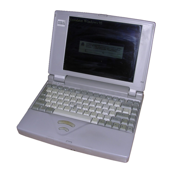
- Page 3 The sound system provides a volume control dial and jacks to connect external audio devices: headphone, microphone, and audio line-in. The T2150 series Personal Computer is shown in figure 1-1. Figure 1-1 T2150 series personal computer T2150 Series...
-
Page 4: System Unit Block Diagram
System Unit Block Diagram Figure 1-2 is a block diagram of the T2150 series system unit. Figure 1-2 T2150 series system board block diagram T2150 Series... - Page 5 The T2150 series system board has the following functional components: One Intel DX4-75 32-bit microprocessor. Intel DX4 operates at 75 MHz and 3.3 volts. Standard RAM 4 Mbytes, two 1024x16-bit chips with no parity bit. (T2150CDS) 8 Mbytes, four 1024x16-bit chips with no parity bit. (T2150CDT) 5-volt operation.
- Page 6 Clock/Reset/Suspend control CPU clock control STPCLK# and INTR/NMI/SMI# adjustment SMI control Current pass-through control Suspend/Resume sequence Reset generation DMA control Timing signal generation for DRAM Cache control DRAM address control Level Shift Gate Array control VGA chip control T2150 Series...
- Page 7 This gate array has the following functions: Level shift 5V data bus <==> 3V data bus Video Controller LSI (C&T 65545) The T2150 series internal display controller (3.3/5 volts operation) controls the internal VGA display and external SVGA compatible display.
-
Page 8: Inch Floppy Disk Drive
The T2150 series 3.5-inch Floppy Disk Drive (FDD) is a thin, high-performance reliable drive that supports 720-KB (formatted) 2DD and 1.44-MB (formatted) 2HD 3.5-inch floppy disks. The T2150 series FDD is shown in figure 1-3. The specifications for the FDD are described in table 1-1. Figure 1-3 3.5-inch FDD Table 1-1 3.5-inch FDD specifications... -
Page 9: Inch Hard Disk Drive
2.5-inch magnetic disk and mini-winchester type magnetic heads. The T2150 series supports 260 million bytes (250MB) (TEG only) and 520 million bytes (500 MB) drive. The T2150 series HDD is shown in figure 1-4. Specifications for the HDD are described in table 1-2. Figure 1-4 2.5-Inch HDD Table 1-2 2.5-inch HDD specifications... - Page 10 25-pin flat cable. The T2150 series pointer control stick, located in the center of the keyboard, provides convenient control of the cursor without requiring desk space for a mouse. The keyboard is shown in figure 1-5.
- Page 11 This drive supports the following formats: Audio CD Photo CD ISO 9660 The T2150 series CD-ROM drive is shown is figure 1-6. The specifications for the CD-ROM drive are described in table 1-3. Figure 1-6 CD-ROM Table 1-3 CD-ROM specifications...
- Page 12 Figure 1-7 STN color LCD Table 1-4 STN color LCD specifications Item Specifications Number of Dots (dots) 640x480 Dot pitch (mm) 0.33x0.33 Display area (mm) 217.2 (W)x164.4 (H) Contrast (Typically) 20:1 FL current (mA) FL frequency (KHz) 1-12 T2150 Series...
- Page 13 The FL inverter board supplies high frequency current to light the LCD’s Fluorescent Lamp. The specifications for the FL inverter are described in table 1-5. Table 1-5 STN color FL inverter board specifications Item Specifications Input Voltage (VDC) Power 4.25 Output Voltage (VAC) 1,100 Current (mA) Frequency (KHz) T2150 Series 1-13...
- Page 14 Figure 1-8 TFT color LCD Table 1-6 TFT color LCD specifications Item Specifications Number of dots (dots) 640x480 Dot pitch (mm) 0.33 (W)x0.33 (H) Display area (mm) 211.2 (W)x158.4 (H) Contrast 60:1 (minimum) FL current (mA) FL frequency (KHz) 1-14 T2150 Series...
- Page 15 The FL inverter board supplies high frequency current to light the LCD’s Fluorescent Lamp. The specifications for the FL inverter are described in table 1-7. Table 1-7 FL inverter board specifications Item Specifications Input Voltage (VDC) Power 4.25 Output Voltage (VAC) 1,100 (r.m.s.) Current (mA) Frequency (KHz) T2150 Series 1-15...
-
Page 16: Power Supply
Power Supply The power supply provides five kinds of voltages to the T2150 series system board. The T2150 series power supply has one microprocessor and it operates at 500 KHz. It contains the following functions: Determines if the AC cord or battery is connected to the computer. - Page 17 The backup and main battery maintain the state of the computer when you enable AutoResume. Battery Indicator The Battery indicator is located on the front of the T2150 series. The indicator shows the status of the removable battery pack. The status of each can be determined by color: Orange The battery is being charged.
- Page 18 The battery or AC output voltage is abnormal. The charge current is abnormal. Trickle Battery Charge When the main battery is fully charged and the AC power cord is attached, the power supply microprocessor automatically changes quick charge to trickle charge. 1-18 T2150 Series...
- Page 19 Table 1-12 shows the charging time and data preservation period of the RTC battery. Table 1-11 RTC battery charging/data preservation time Time Charging Time With AC power 48 H or main battery Data preservation period (full charge) 1 month T2150 Series 1-19...
-
Page 20: Troubleshooting
Troubleshooting Chapter 2 describes how to determine if a Field Replaceable Unit (FRU) in the T2150 series is causing the computer to malfunction. The FRUs covered are: System Board(s) Sound Board Floppy Disk Drive Hard Disk Drive CD-ROM Drive Keyboard... -
Page 21: Troubleshooting Flowchart
Use the flowchart in figure 2-1 as a guide for determining which troubleshooting procedures to execute. Before going through the flowchart steps, verify the following: Verify with the customer that Toshiba MS-DOS is installed on the hard disk. Non- Toshiba operating systems can cause the computer to malfunction. - Page 22 Figure 2-1 Troubleshooting flowchart (1/2) T2150 Series...
- Page 23 If an error is detected on the floppy disk test, perform the floppy disk drive troubleshooting procedures in section 2.5. If an error is detected on the hard disk test, perform the hard disk drive troubleshooting procedures in section 2.6. T2150 Series...
- Page 24 2.7. If an error is detected on the display test, perform the display troubleshooting procedures in section 2.8. If an error is detected on the CD-ROM test, perform the CD-ROM drive trouble- shooting procedures in section 2.9. T2150 Series...
-
Page 25: Power Supply Troubleshooting
If the AC IN indicator does not light, the AC power cord is not supplying power to the T2150 series or the AC power cord is not attached to the T2150 series, go to Check 1. If the AC IN indicator is flashing orange, the AC power cord’s voltage supply is abnormal or the power supply is not functioning properly, go to Check 2. - Page 26 AC power cord is charging the T2150 series battery pack. If the Battery LED indicator glows green, the AC power cord is connected and the battery is fully charged.
- Page 27 AC IN plug located on the AC PS unit. Replace the AC PS unit if it is damaged. Refer to chapter 4 for instructions on how to disassemble the T2150 series, and then perform the following check: Check 1 Replace the AC PS unit with a new one and restart the system.
- Page 28 If an error message is shown on the display, perform Check 1. If there is no error message, go to Procedure 2. If the Toshiba MS-DOS is properly loaded, go to Procedure 3. Check 1 If one of the following error messages is displayed on the screen, press the F1 key as the message instructs.
- Page 29 This error message appears when data stored in RAM under the resume function is lost because the battery has become discharged or the system board is damaged. Go to Procedure 3. If any other message appears, perform Check 3. 2-10 T2150 Series...
- Page 30 (19) PIC #1 ERROR (20) PIC #2 ERROR (21) KBC ERROR (22) HDC ERROR (23) HDD #0 ERROR (24) HDD #1 ERROR (25) NO FDD ERROR (26) FDC ERROR (27) TIMER INTERRUPT ERROR (28) RTC UPDATE ERROR 2-11 T2150 Series...
- Page 31 Plug the printer port LED into the T2150 series parallel port. Hold down the space bar and turn on the T2150 series power. Read the LED status from left to right as you are facing the back of the computer.
- Page 32 PIC #X ERROR Mouse initialization — KBC initialization KBC ERROR HDD initialization HDC ERROR/HDD #0 ERROR FDD initialization FDC ERROR/NO FDD ERROR Printer initialization — SIO initialization — Timer initialization RTC UPDATE ERROR TIMER INTERRUPT ERROR NDP initialization — 2-13 T2150 Series...
- Page 33 To use the printer port LED follow these steps: Turn on the T2150 series power, then set to resume mode. Turn off the T2150 series power. Plug the printer port LED into the T2150 series parallel port.
- Page 34 If an error is detected during these tests, go to Procedure 5. Procedure 5 Replacement Check The system board or the sound board may be damaged. Disassemble the T2150 series follow- ing the steps described in chapter 4, Replacement Procedures, and perform the following checks: Check 1.
- Page 35 Floppy Disk Drive Troubleshooting This section describes how to determine if the T2150 series external 3.5-inch floppy disk drive is functioning properly. Perform the steps below starting with Procedure 1 and continuing with the other procedures as required. Procedure 1:...
- Page 36 Procedure 2 Diagnostic Test Program Execution Check The Floppy Disk Drive Diagnostic Test program is stored on the T2150 series Diagnostics Disk. After loading Toshiba MS-DOS, run the diagnostic program. Refer to Chapter 3, Tests and Diagnostics, for more information about the diagnostics test procedures.
- Page 37 The FDD or its cable may be defective or damaged. Replace the FDD with a new one following the steps in chapter 4, Replacement Procedures. If the FDD is still not functioning properly, perform Check 4. Check 4 Replace the system board with a new one following the steps in chapter 4. 2-18 T2150 Series...
-
Page 38: Hard Disk Drive Troubleshooting
BACKUP. Procedure 1 Partition Check Insert the Toshiba MS-DOS system disk and turn on the computer. Then perform the follow- ing checks: Check 1 Type C: and press Enter. If you cannot change to drive C, go to Check 2. If you can change to drive C, go to Procedure 2. - Page 39 Procedure 2 Message Check When the T2150 series HDD does not function properly, some of the following error mes- sages may appear on the display. Start with Check 1 below and perform the other checks as instructed. Check 1 If any of the following messages appear, perform Check 2. If the following mes-...
- Page 40 Procedure 3 Format Check The T2150 series HDD is formatted using the low level format program and the MS-DOS FORMAT program. To format the HDD, start with Check 1 below and perform the other steps as required. Check 1 Using the Toshiba MS-DOS system disk, partition the hard disk using the FDISK command.
- Page 41 Procedure 4 Diagnostic Test Program Execution Check The HDD test program is stored in the T2150 series Diagnostics Disk. Perform all of the HDD tests in the Hard Disk Drive Test. Refer to chapter 3, Tests and Diagnostics, for more information about the HDD test program.
-
Page 42: Keyboard Troubleshooting
Keyboard Troubleshooting To determine if the T2150 series keyboard is functioning properly, perform the following procedures. Start with Procedure 1 and continue with the other procedures as instructed. Procedure 1: Diagnostic Test Program Execution Check Procedure 2: Connector and Replacement Check... -
Page 43: Display Troubleshooting
Procedure 2 External CRT Check Connect the external CRT to the T2150 series external monitor port, then boot the computer. The computer automatically detects the external CRT even if Resume mode is enabled. If the external CRT works correctly, the internal LCD display may be damaged. Go to Proce- dure 4. - Page 44 (T2150CDT) cables as shown below. Any of these cables may be disconnected. Disassemble the display unit and check the following cable connections. Refer to chapter 4, Replacement Procedures, for more information about how to disassemble the computer. Figure 2-3 T2150CDS display connection 2-25 T2150 Series...
- Page 45 Figure 2-4 T2150CDT display connection If any of these cables is not connected, firmly reconnect it and repeat Procedures 1 and 2. If the problem still exists, perform Procedure 5. 2-26 T2150 Series...
- Page 46 Replace the display cable with a new one and test the display again. If the problem still exists, perform Check 6. Check 6 The system board may be damaged. Replace the system board with a new one. 2-27 T2150 Series...
- Page 47 CD-ROM Drive Troubleshooting This section describes how to determine if the T2150 series internal CD-ROM drive is func- tioning properly. Perform the steps below starting with Procedure 1 and continuing with the other procedures as required. Procedure 1: CD Cleaning Check...
- Page 48 The CD-ROM drive is connected to the system board and sound board by the CD-ROM drive cable. This cable may be damaged or disconnected from the system board. Disassemble the T2150 series following the steps described in Chapter 4, Replacement Procedures, and per- form the following checks: Check 1 Make sure the CD-ROM cable is firmly connected to the system board.
-
Page 49: The Diagnostic Test
The Diagnostic Test This chapter explains how to use the T2150 series Diagnostic Test program to test the func- tions of the T2150 series hardware modules. The Diagnostics Program is stored on the T2150 series Diagnostic Disk. The Diagnostic Test consists of 8 programs that are grouped into the Service Program Module (DIAGNOSTIC TEST MENU) and the Test Program Module (DIAGNOSTIC TEST). - Page 50 EXPANSION TEST SOUND TEST CD-ROM TEST You will need the following equipment to perform some of the T2150 series Diagnostic test programs. The T2150 series Diagnostics Disk (all tests) A formatted working disk for the floppy disk drive test (all tests) 3.5-inch 2HD/2DD disk for external 3.5-inch FDD...
-
Page 51: Executing The Diagnostic Test
Specify Exit NOTE: To exit the T2150 series DIAGNOSTIC TEST MENU, press the Esc key. If a test program is in progress, press Ctrl + Break to exit the test program or press Ctrl + C to stop the test program. - Page 52 02 - HW status 03 - Version check 99 - Exit to DIAGNOSTIC TEST MENU ↑↓→← Select items Enter Specify Exit NOTE: The menu displayed by your T2150 series may be slightly different from the one shown above. T2150 Series...
- Page 53 Use the arrow keys to move the cursor to the desired option and press Enter. Table 3-1 in section 3.3 describes the function of each test on the subtest menu. Table 3-3 in section 3.15 describes the error codes and error status for each error. T2150 Series...
-
Page 54: Subtest Names
320*200 Graphics display 640*200 Graphics display 640*350/480 Graphics display Display page “H” pattern display/Border color LED/DAC pallet TFT color display (T2150CDT only) Sequential read Sequential read/write Random address/data Write specified address Read specified address PRINTER Ripple pattern Function Wraparound T2150 Series... -
Page 55: Table Of Contents
W-R-C specified address REAL TIMER Real time Backup memory Real time carry NDP test EXPANSION PCMCIA wraparound SOUND CODEC (REC/PLAY) FM Synthesizer SINE wave playback Joystick Joystick/MIDI wrap around CODEC (Line In/Out) CD-ROM Sequential read Read specified address Random address/data T2150 Series... -
Page 56: Subtest No
Notch signal = 2HD Table 3-2 describes the hardware bit status for each bit tested. Pressing Enter returns you to the Sub-Test Menu. Table 3-2 Hardware bit status H/W status CPU clock speed 75 MHz 37.5 MHz Media type T2150 Series... - Page 57 S key. When the read information is higher, the display is unchanged. ROM-BIOS = V1.00 : OK V1.10 ROM(BOOT) = V1.00 : OK V1.00 KBC Version = V1.26 : NG V1.00 PS Micom Version = V1.35 : OK V1.35 Reference data Current data T2150 Series...
-
Page 58: Memory Test
HIMEM.SYS must be deleted from the CONFIG.SYS file. This subtest writes constant data and address data to extended memory (maxi- mum address 100000h) then reads new data and compares the result with the original data. The constant data is FFh, AAh, 55h, and 00h. 3-10 T2150 Series... - Page 59 (‘7000’:’Program’ size to ‘7000’:=7FFF’ (32 KB)) to check the hit-miss ratio (on/off status). One test takes 3 seconds. Number of miss hit < Number of hit → OK Number of miss hit ≥ Number of hit → Fail 3-11 T2150 Series...
-
Page 60: Keyboard Test
To execute the Keyboard Test, select 3 from the DIAGNOSTIC TEST MENU, press Enter and follow the directions displayed on the screen. The Keyboard test contains two subtests that test the T2150 series keyboard actions. Move the highlight bar to the subtest you want to execute and press Enter. - Page 61 If this test does not detect an error, it returns to the subtest menu. If this test detects an error, the following message appears: KBD - MOUSE INTERFACE ERROR [[ HALT OPERATION ]] 1: Test end 2: Continue 3: Retry 3-13 T2150 Series...
- Page 62 If two IPS switches are pressed, it returns to the subtest menu. ***** IPS TEST PROGRAM (V1.00) ***** << PRESS BUTTON1 + BUTTON2 THEN END >> When the button is pressed, it alternates as shown below. 3-14 T2150 Series...
-
Page 63: Display Test
To execute the Display Test, select 4 from the DIAGNOSTIC TEST MENU, press Enter and follow the directions displayed on the screen. The Display test contains ten subtests that test the T2150 series display in various modes. Move the highlight bar to the subtest you want to execute and press Enter. - Page 64 In this subtest, the character set (addressed 00h to FFh) is displayed in the 40*25 character mode as shown below. Press [Enter] KEY To exit this subtest and return to the DISPLAY TEST menu, press Ctrl + Break. 3-16 T2150 Series...
- Page 65 This subtest displays two color sets for the color display in 320x200 dot graphics mode 4 and D. One example is shown below: GREEN BROWN CYAN MAGENTA WHITE Pressing Enter toggles between tests. To exit this subtest and return to the DISPLAY TEST menu, press Ctrl + Break. 3-17 T2150 Series...
- Page 66 640*XXX GRAPHICS DISPLAY EVEN DOTS ODD DOTS ALL DOTS DRIVEN DRIVEN DRIVEN PRESS [Enter] KEY Pressing Enter changes the size of the displayed image. To exit this subtest and return to the DISPLAY TEST menu, press Ctrl + Break. 3-18 T2150 Series...
- Page 67 HHHHHHHHHHHHHHHHHHHHHHHHHHHHHHHHHHHHHHHHHHHHHHHHHH Pressing Enter displays the following message: Setting the color CRT (1:yes/2:no) ? If an external CRT display is connected to the T2150 series, choose 1 to display the following message: [Border color test (7 times press [Enter] key] Press Enter to execute the border color test. To exit this subtest and return to the DISPLAY TEST menu, press Ctrl + Break.
- Page 68 64 shades of red, green, and blue successively and the last three display 64 shades of red, green, and blue. Also, it sets the video mode ‘5F,’ and displays 256 colors. Press Enter to change the display. Press Ctrl + Break to exit. 3-20 T2150 Series...
-
Page 69: Floppy Disk Test
Enter and follow the directions displayed on the screen. The Floppy Disk test contains five subtests that test the T2150 series external floppy disk drive. The following messages will appear after selecting the Floppy Disk Test from the DIAGNOSTIC TEST MENU. Answer each question with an appropriate response to execute the test. - Page 70 01. The data is then read and compared to the original data. Subtest 04 Write Specified Address This subtest writes specified data to a specified track, head, and address. Subtest 05 Read Specified Address This subtest reads data from a specified track, head, and address. 3-22 T2150 Series...
-
Page 71: Printer Test
The Printer Test contains three subtests that test the output of the printer connected to the T2150 series. The following messages will appear after selecting the Printer Test from the DIAGNOSTIC TEST MENU. Answer each of the following questions with an appropriate response to execute the test. -
Page 72: Wraparound (Board)
NOTE: To execute this subtest, a printer wraparound connector must be connected to the computer’s printer port. The printer wraparound connector (34M741986G01) wiring diagram is described in Appendix G. This subtest checks the output and bidirectional modes of the data control and status lines through the printer wraparound connector. 3-24 T2150 Series... -
Page 73: Board (#1) <=> Board (#2)
To execute the Async Test, select 7 from the DIAGNOSTIC TEST MENU, press Enter and follow the directions displayed on the screen. The async test contains six subtests that test the T2150 series asynchronous communication functions. Move the highlight bar to the subtest you want to execute and press Enter. -
Page 74: Point To Point (Send)
This subtest is used with subtest 03 described above. This subtest receives the data from the send side, then sends the received data. Subtest 05 Interrupt Test This subtest checks the Interrupt Request Level of IRQ 4, 3, and 5 from the send side. 3-26 T2150 Series... -
Page 75: Hard Disk Test
CAUTION: The contents of the hard disk will be erased when subtest 02, 03, 04, 05, 06, 08, 09, or 10 is executed. Before running the test, transfer the contents of the hard disk to a floppy disk(s). This can be done with the BACKUP command in the Toshiba Companion Utility. -
Page 76: Sequential Read
Forward sequential • Reverse sequential • Random Subtest 03 Random Address/Data This subtest writes random data to random addresses on the HDD cylinder, head and sector. This data is then read and compared to the original data. 3-28 T2150 Series... -
Page 77: Cross Talk & Peak Shift
This subtest writes specified 2-byte data to all of the cylinders on the HDD. Subtest 10 W-R-C specified address This subtest writes data to a specified cylinder and head on the HDD, then reads the data and compares it to the original data. 3-29 T2150 Series... -
Page 78: Real Time
To execute the Real Timer Test, select 9 from the DIAGNOSTIC TEST MENU, press Enter and follow the directions on the screen. The real timer test contains three subtests that test the T2150 series real timer functions. Move the highlight bar to the subtest you want to execute and press Enter. -
Page 79: Real Time Carry
Current date : 12-31-1992 Current time : 23:59:58 Pressing Enter displays the following Current date : 01-01-1993 Current time : 00:00:00 PRESS [Enter] KEY TO EXIT TEST Press Ctrl + Break to exit. 3-31 T2150 Series... -
Page 80: 3.13 Ndp Test
The NDP test contains one subtest that tests the T2150 series NDP functions. Subtest 01 This test checks the following function of NDP: Control word Status word Addition Multiplication Press Ctrl + Break to exit. 3-32 T2150 Series... -
Page 81: Expansion Test
Contents 00001 Address line 00001 REG#, CE#1, CE#2 nn=A0, 90, 80, 00 00002 Data line ww=write data, rr=read data 00003 –– –– Speaker line 00004 40, 80 Wait line (40<xx<80) 00005 Other lines (BSY#, BVD1) nn=21, 00 3-33 T2150 Series... -
Page 82: Codec (Rec/Play)
3.15 SOUND Test To execute the SOUND test, select 12 from the DIAGNOSTICS TEST MENU, press Enter and follow the directions on the screen. The SOUND test contains one subtest that tests the T2150 series SOUND functions. Subtest 01 CODEC (REC/PLAY) NOTE: To execute this subtest, the internal microphone and internal headphone (or internal speaker) are required. - Page 83 After making the connections, a dialogue box will be displayed. Press Enter to play a recorded sound. About three seconds after the recorded sound is played, the dialogue box will be displayed again. NOTE: A port replicator must be connected to conduct the line-out test. 3-35 T2150 Series...
-
Page 84: Sequential Read
First make sure the CD-ROM driver (CDROMDRV.COM) is installed and insert the test media CD (Toshiba-EMI Test Disk TDY-03). To execute the CD-ROM test, select 13 from the DIAGNOSTICS TEST MENU, press Enter and follow the directions on the screen. The CD-ROM test contains one subtest that tests the T2150 series CD-ROM functions. -
Page 85: Error Code And Error Status Names
Time Out Error Write Buffer Error Printer Time Out Fault Select Line Out Of Paper Power Off Busy Line ASYNC DSR On Time Out CTS On Time Out RX-READY Time Out TX-BUFFER Full Time Out Parity Error 3-37 T2150 Series... - Page 86 Control Word Error Status Word Error Bus Error Addition Error Multiply Error PCMCIA Address Line Error REG# Line Error CE#1 Line Error CE#2 Line Error DATA Line Error WAIT Line Error BSY# Line Error BVD1 Line Error No PCMCIA 3-38 T2150 Series...
- Page 87 Device name Error code Error status name CD-ROM BAD COMMAND ILLEGAL LENGTH UNIT ATTENTION MEDIA CHANGE REQUEST MEDIA DETECTED ADDITIONAL SENSE BOUNDARY ERROR CORRECTED DATA ERROR DRIVE NOT READY SEEK ERROR TIME OUT RESET ERROR ADDRESS ERROR 3-39 T2150 Series...
-
Page 88: Hard Disk Test Detail Status
“1” --- Drive is ready for data transfer. CORR “0” --- Other (Corrected data) “1” --- Correctable data error is corrected. “0” --- Other (Index) “1” --- Index is sensed. “0” --- Other (Error) “1” --- The previous command was terminated with some error. 3-40 T2150 Series... - Page 89 “1” Illegal command error or a drive status error occurs. TK00 “0” The hard disk has found track 0 during a recalibrate command. (Track 0) “1” The hard disk could not find track 0 during a recalibrate command. —— Not used. 3-41 T2150 Series...
-
Page 90: Hard Disk Format
CAUTION: The contents of the hard disk will be erased when this program is executed. Before executing the function, transfer the contents of the hard disk onto a floppy disk(s). This can be done with the BACKUP in the Toshiba Companion Utility. See the Toshiba MS-DOS manual for details. - Page 91 CAUTION: After the HDD has been formatted, execute the Toshiba MS-DOS FDISK command, to partition the HDD. Next, execute the Toshiba MS-DOS FORMAT com- mand. Refer to the Toshiba MS-DOS manual for more information about using these commands. Selecting TEST 2 and pressing Enter in the DIAGNOSTIC MENU displays the following messages: DIAGNOSTICS - HARD DISK FORMAT : VX.XX...
- Page 92 (f) below. Track verification A check is made of all tracks and if an ECC error, ECC-correctable-data error, or record-not-found error is detected at a track, that track is automati- cally formatted as a bad track. 3-44 T2150 Series...
- Page 93 Drive number select (1:#1, 2:#2) ? Bad tracks will be displayed in the format shown below. [[cylinder, head = 0123 03]] Press Enter to return to the Hard Disk Format menu. 3-45 T2150 Series...
-
Page 94: Head Cleaning
Remove the Diagnostics Disk from the FDD. Insert the cleaning disk and press Enter. When the cleaning start message appears, the FDD head cleaning has begun. The display automatically returns to the DIAGNOSTIC MENU when the program is completed. 3-46 T2150 Series... -
Page 95: Log Utilities
001 FDD 01 0000 180 00001 00 00 FDD - TIME OUT ERROR Address Error status Pass count HDC status Subtest number Read data Test name Write data Error count Error status name [[1:Next,2:Prev,3:Exit,4:Clear,5:Print,6:FD Log Read,7:FD Log Write]] 3-47 T2150 Series... - Page 96 The 7 key writes the log information to a floppy disk. In the case of “error retry OK,” a capital “R” will be placed at the beginning of the error status. However, it is not added to the error count. 3-48 T2150 Series...
-
Page 97: Running Test
Printer wrap around test (Y/N) ? Selecting Y (yes) executes the printer wraparound test. A printer wraparound connector must be connected to the parallel port on the back of the T2150 series to properly execute this test. Select Y or N and press Enter. The following message will appear: Serial #A wrap around test (Y/N) ? Selecting Y (yes) executes the ASYNC wraparound test. - Page 98 Select Yes or No and press Enter. The following message will appear : Mount the work disk(s) on the drive(s), then press [Enter] key. [Warning : The contents of the disk(s), will be destroyed.] This program is executed continuously. To terminate the program, press Ctrl + Break. 3-50 T2150 Series...
-
Page 99: Floppy Disk Drive Utilities
FDD and HDD. FORMAT NOTE: This program is only for testing a floppy disk drive. The option is different from the Toshiba MS-DOS FORMAT command. This program can format a 5.25-inch or 3.5-inch floppy disk in the following formats: 2D: Double-sided, double-density, 48/67.5 TPI, MFM mode, 512 bytes, 9 sectors/track. - Page 100 When COPY is selected, the following message appears: FLOPPY DISK FORMAT & COPY : VX.XX Type select (0:2DD-2DD,1:2D-2D,2:2D-2HD,3:2HD-2HD) ? Selecting a media/drive type number will display a message similar to the one below: Insert source disk into drive A: Press any key when ready. 3-52 T2150 Series...
- Page 101 —— Max. address —— [Track ] = 0079 [ Head ] = 01 [Sector] = 09 Track number ?? Set the track number you want to dump. The system will access the disk and dump a list. 3-53 T2150 Series...
-
Page 102: System Configuration
3.24 System Configuration 3.24.1 Function Description The System Configuration program contains the following configuration information for the T2150 series: BIOS ROM version Boot ROM version The number of math co-processors Base memory size The number of floppy disk drives The number of ASYNC ports... - Page 103 Hard disk HDD Mode I/O Ports Serial port Parallel Port Sound System Power on Password Others Power-up Modes CPU Cache Processing Speed Alarm Volume System Beep Panel Power On/Off Alarm Power On Keyboard Pointing Devices Boot Priority 3-55 T2150 Series...
-
Page 104: Accessing The Setup Program
"MEMORY total" item displays the actual memory installed. 2. The "Panel Power On/Off " item appears only when the T2150 series computer is in Resume mode. 3. The "Battery Level" option appears only when the system cannot detect the battery charge. For example, when the battery is replaced. - Page 105 The SYSTEM SETUP screen is divided into functionally related groups. This section describes each group and its options. NOTE: The functions described in this section can also be changed using Toshiba’s Hardware Setup program in Windows. You can access this program in the Toshiba Utilities group in Windows Program Manager.
- Page 106 T2150CDS’s STN display when the LCD Display mode is set to “Color.” T2150CDT TFT display 256K Colors Displays 256 colors out of 262,144 colors. (Default) T2150CDS STN display 222K Colors Displays 256 colors out of 226,981 colors. (Default) 4096 Colors Displays 256 colors out of 4096 colors. 3-58 T2150 Series...
- Page 107 BATTERY SAVE OPTION. Full Power The following shows full power settings. BATTERY SAVE OPTIONS CPU Sleep Mode Disabled Display Auto Off Disabled (T2150CDS) 30 Min. (T2150CDT) HDD Auto Off Disabled System Auto OFF Disabled LCD Brightness Bright 3-59 T2150 Series...
- Page 108 Min. Automatically turns off power to the LCD panel’s illumination if the panel is not used for the duration set. The duration xx can be set to 1, 3, 5, 10, 15, 20, or 30 minutes. 3-60 T2150 Series...
- Page 109 Battery Level options will be displayed to enable you to set the charge level to 100%, 75%, 50%, or 25%. 100% charge 75% charge 50% charge 25% charge E ??? Charge is unknown (Displayed in TSETUP) 3-61 T2150 Series...
- Page 110 The options for this setting are Output (default) and Bi-Directional. Option Mode Output For most printers, the port should be set to Output. With some other parallel devices, the setting should be Bi-Directional. 3-62 T2150 Series...
- Page 111 IRQ10. If you cannot change the software setting, change the hardware setting to IRQ7. DMA (direct memory access) channel Use this option to set the DMA channel. The available settings are: Channel 0, Channel 1 (default) 3-63 T2150 Series...
- Page 112 Registered The password has been registered. Not registered The password has not been registered. For details on setting the password, refer to the T2150 series Reference Manual. Others Whether or not you need to configure the computer with these options depends primarily on the kind of software or peripherals you use.
- Page 113 Disables the feature. Panel Power On/Off This option allows you to automatically turn your T2150 series computer on or off by opening or closing the display panel. If this feature is enabled when the computer is in Resume mode, the system is automatically powered off when the display panel is closed and pow- ered on when the panel is opened.
- Page 114 KEYBOARD Int. Keyboard key layout Normal Ext.Keyboard “Fn” key equivalent Disabled Int. Keyboard key layout This option lets you select the arrangement of the CapsLock, Ctrl, and Alt keys according to the following illustrations: Alternative Normal (default) 3-66 T2150 Series...
- Page 115 The computer looks for bootable files first on the HDD and next on the diskette drive. You can reverse the order by holding down the F10 key while the computer is booting. This procedure does not affect the setting. 3-67 T2150 Series...
- Page 116 FRUs that need to be removed in order to remove others. Always start by removing the battery pack, then follow the lines on the chart to determine which FRU you must remove next in order to repair the one you think is causing the T2150 series to operate improperly.
- Page 117 Before You Begin Look over the procedures in this section before you begin disassembling the T2150 series. Familiarize yourself with the disassembly and reassembly steps. Begin each procedure by removing the AC power cord and the battery pack as instructed in section 4.2, The Battery Pack: Do not disassemble the T2150 series unless it is operating abnormally.
- Page 118 FRU. After installing an FRU in the T2150 series, confirm that the FRU and the T2150 series are functioning properly.
- Page 119 Proper use of these devices will increase the success rate of your repairs and lower the cost for damaged or destroyed parts. The following equipment is necessary to disassemble and reassemble the T2150 series: One M2 Phillips screwdriver to remove and replace screws.
- Page 120 The Battery Pack Removing the Battery Pack To remove the T2150 series battery pack, follow the steps below and refer to figures 4-1 to 4-3. Turn the computer's power off. Remove all cables connected to the computer and open the display panel.
- Page 121 Pull up on the plastic tab at the right side of the battery pack to lift the battery pack slightly. Be careful not to pull too hard or try to lift the battery pack more than about a finger’s width. Grasp the battery pack and lift it out. Figure 4-3 Removing the battery pack T2150 Series...
- Page 122 Installing the Battery Pack WARNING: There is danger of explosion if the battery is incorrectly replaced. Use only the same or equivalent battery recommended by Toshiba. Return spent batteries to your dealer for environmentally safe disposal. To install a battery pack, follow the steps below and refer to figures 4-1 to 4-3.
- Page 123 Optional Memory Module Removing the Optional Memory Module To remove an optional memory module from the T2150 series, follow the steps below and refer to figures 4-4 and 4-5. Turn the computer's power off. Disconnect the AC power cord and all external cables connected to the T2150 series.
- Page 124 Gently work the module out of the connector and remove it from the unit. CAUTION: DO NOT touch the connecting edge of the memory module. Debris or oil in or on the connector may cause memory access problems. T2150 Series...
- Page 125 Installing the Optional Memory Module To install an optional memory module in the T2150 series, follow the steps below and refer to figure 4-6. Insert the memory module, connectors first, into the computer’s connectors. Note the notch at the corner of the module. This notch should be on the right as you insert the module (figure 4-6).
- Page 126 Optional PCMCIA Card Removing an Optional PCMCIA Card To remove an optional PCMCIA card from the T2150 series, follow the steps below and refer to figures 4-7 and 4-8. Turn off the power. Disconnect the AC power card and all external cables con- nected to the T2150 series.
- Page 127 Installing an Optional PCMCIA Card To install an optional PCMCIA card in the T2150 series, follow the steps below and refer to figure 4-9. To install a PCMCIA card, carefully insert the card, making sure the card is right side up and the contact surface is inserted first (figure 4-9).
- Page 128 Keyboard Removing the Keyboard To remove the T2150 series keyboard, follow the steps below and refer to figures 4-10 and 4-11. Turn the computer's power off. Disconnect the AC power cord and all external cables connected to the T2150 series.
- Page 129 (figure 4-11). Figure 4-11 Removing the keyboard Installing the Keyboard To install the T2150 series keyboard, follow the steps below and refer to figures 4-10 and 4-11. 1. Connect the keyboard cable to the pressure plate connector (PJ14) on the system board (figure 4-11).
- Page 130 Hard Disk Drive and Sound Board Removing the Hard Disk Drive and Sound Board To remove the T2150 series hard disk drive and sound board, follow the steps below and refer to figures 4-12 and 4-13. Turn the computer's power off. Disconnect the power cable and all external cables connected to the T2150 series.
- Page 131 (figure 4-14). Slide the HDD to the left to disconnect the HDD connector (figure 4-14). Figure 4-14 Removing the HDD with bracket 11. Lift the HDD out of the system unit. 4-16 T2150 Series...
- Page 132 Installing the Hard Disk Drive and Sound Board To install the T2150 series hard disk drive, follow the steps below and refer to figures 4-12 through 4-14. Place the HDD in the HDD slot and slide the HDD to the right. Make sure the HDD connects to the HDD connector on the system board (PJ502) (figure 4-14).
- Page 133 Top Cover, Display Assembly, and Speaker Removing the Top Cover, Display Assembly, and Speaker To remove the T2150 series top cover, follow the steps below and refer to figures 4-15 to 4-17. Turn the computer's power off. Disconnect the power cable and all external cables connected to the T2150 series.
- Page 134 Disconnect the display cable from PJ17 on the system board (figure 4-17). Disconnect the speaker cable from PJ 501 (figure 4-18). Lift the top cover with display assembly straight up out of the bottom unit (figure 4-17). 4-19 T2150 Series...
- Page 135 Figure 4-17 Removing the top cover & display assembly 4-20 T2150 Series...
- Page 136 Installing the Top Cover, Display assembly, and Speaker To install the T2150 series top cover, follow the steps below and refer to figures 4-15 to 4-17. Seat the top cover with display assembly (figure 4-17). Connect the display sensor switch cable to PJ11 on the system board (figure 4-17).
- Page 137 AC PS Unit Removing the AC PS Unit To remove the T2150 series AC PS unit, follow the steps below and refer to figure 4-18. Turn the computer's power off. Disconnect the AC power cord and all external cables connected to the T2150 series.
- Page 138 Installing the AC PS unit To install the T2150 series AC PS unit, follow the steps below and refer to figure 4-18. Seat the LED cover/power switch frame on the system unit (figure 4-18). Secure three M2.5x8 silver screws on the LED cover/power switch frame (figure 4-18).
- Page 139 CD-ROM Drive Removing the CD-ROM Drive To remove the T2150 series CD-ROM drive, follow the steps below and refer to figures 4-19 and 4-20. Turn off the power. Disconnect the AC power cord and all external cables con- nected to the T2150 series.
- Page 140 Figure 4-20 Removing the HDD Installing the CD-ROM Drive To install the T2150 series CD-ROM drive, follow the steps below and refer to figures 4-19 and figures 4-20. Secure the bracket to the HDD with four M2x3 black screws (figure 4-20).
- Page 141 4.10 System Board and Backup/RTC Batteries Removing the System Board and Backup/RTC Batteries To remove the T2150 series system board and backup/RTC batteries, follow the steps below and refer to figure 4-21. Turn the computer's power off. Disconnect the AC power cord and all external cables connected to the T2150 series.
- Page 142 Toshiba. Installation of the wrong battery can cause the battery to explode. To install the T2150 series system board and backup/RTC battery, follow the steps below and refer to figure 4-21.
-
Page 143: Display Mask
4.11 Display Mask Removing the Display Mask To remove the T2150 series display mask, follow the steps below and refer to figure 4-22. Turn off the power. Disconnect the AC power cord and all external cables con- nected to the T2150 series. - Page 144 Installing the Display Mask To install the T2150 series display mask, follow the steps below and refer to figure 4-22. Set the display mask in place and secure the latches beginning with the display supports (figure 4-22). Continue along the bottom of the display (three latches), along the sides (four latches), and across the top (six latches) (figure 4-22).
- Page 145 (figure 4-23). Remove one M2.5x6 screw securing the volume board (figure 4-23). Disconnect the volume cable from the connector on the volume board (Figure 4-23). Disconnect the internal microphone. Figure 4-23 Removing the FL inverter and volume board 4-30 T2150 Series...
- Page 146 Secure the FL inverter board with two M2.5x6 screws (figure 4-23). Install the display mask, optional PCMCIA card, optional memory card, and battery pack as described in 4.11, and 4.4 back through 4.2. 4-31 T2150 Series...
- Page 147 Carefully rotate the LCD module from left to right out of the display cover and disconnect the display cable from the LCD module (figure 4-24). Figure 4-24 Removing the LCD module CAUTION: Metal edges on the LCD module are sharp, so be careful not to cut yourself. 4-32 T2150 Series...
- Page 148 Secure four M2.5x6 screws with ground cable on the LCD module (figure 4- 24). Install the FL inverter board, display mask, optional PCMCIA card optional memory module, and battery pack as described in sections 4.12, 4.11, and 4.4 back through 4.2. 4-33 T2150 Series...
- Page 149 4.4, and 4.11 through 4.13. Release 11 latches securing the LCD module to its frame (figure 4-25). Turn the LCD module over and remove four screws (figure 4-25). Figure 4-25 Unbending the color LCD module latches 4-34 T2150 Series...
- Page 150 Slip your finger under the P chassis and release the latch securing it to the B/L holder. Gently hold down the LCD module and lift one side of the B/L holder as shown in figure 4-27. As you lift the B/L holder the P chassis securing the holder will rotate out. 4-35 T2150 Series...
- Page 151 Disconnect the FL. Lift the end of the reflector sheet covering the FL and lift out the FL. Be careful not to pull or apply tension to the reflector sheet. Figure 4-28 Lifting the end of the reflector sheet 4-36 T2150 Series...
- Page 152 Replace the two ground plates. Secure the SEG board with four screws. Set the LCD module in its frame and secure it with four screws. Turn the module over and secure the 11 latches of the frame. 4-37 T2150 Series...
- Page 153 Rotate the FL inverter board out of its seating and disconnect the FL inverter cable from CN1 and the FL cable from CN2 on the FL inverter board (figure 4-29). Figure 4-29 Disconnecting the FL inverter board 4-38 T2150 Series...
- Page 154 Secure the FL inverter board with two M2.5x6 screws (figure 4-29). Install the display mask, optional memory module, optional PCMCIA card, and battery pack as described in sections 4.11, 4.4 back through 4.2. 4-39 T2150 Series...
- Page 155 Carefully rotate the LCD module from left to right out of the display cover and disconnect the display cable from the LCD module (figure 4-30). Figure 4-30 Removing the LCD module CAUTION: Metal edges on the LCD module are sharp, so be careful not to cut yourself. 4-40 T2150 Series...
- Page 156 Secure four M2.5x6 screws with the ground cable on the LCD module (figure 4-30). Install the FL inverter board, display mask, optional memory module, optional PCMCIA card, and battery pack as described in sections 4.15, 4.11, 4.4 back through 4.2. 4-41 T2150 Series...
- Page 157 Replace the FL tube in the frame and seat the FL tube cover, then secure it with three small screws (figure 4-31.) Install the LCD module, FL inverter board, display mask, optional PCMCIA card, optional memory module, and battery pack as described in sections 4.16, 4.15, 4.11, and 4.4 back through 4.2. 4-42 T2150 Series...
-
Page 158: Appendix A Handling The Lcd Module
LCD cover before securing the module with screws. Do not force the module into place, because stress can affect its performance. Also, the panel’s polarized surface is easily scarred, so be careful when handing it. T2150 Series... - Page 159 Be sure to quickly wipe off any liquid. Glass is used in the panel, so be careful not to drop it or let it strike a hard object, which could cause breakage or cracks. T2150 Series...
- Page 160 Do not expose the module to direct sunlight or strong ultraviolet rays for long periods. Do not store the module at temperatures below specifications. Cold can cause the liquid crystals to freeze, lose their elasticity or otherwise suffer damage. T2150 Series...
- Page 161 If you transport the module, do not use packing material that contains epoxy resin (amine) or silicon glue (alcohol or oxime). These materials can release gas that can damage the panel's polarization. The TAB IC on the LCD back panel is easily damaged so be very careful when handling it. T2150 Series...
- Page 162 Appendix B Board Layout FHVSY* System Board Figure B-1 FHVSY* system board (front) T2150 Series...
- Page 163 Figure B-2 FHVSY* system board (back) T2150 Series...
- Page 164 FHWSD* Board Figure B-3 FHWSD* board T2150 Series...
- Page 165 PCMCIA Slot Connector PJ17 LCD Connector PJ18 RGB Connector PJ19 LCD Connector CD-ROM Interface Connector PJ12 SYSTEM SPEAKER Connector PJ15 SOUND Interface Connector PJ501 AC PS Connector PJ502 Main Battery Connector 2A Fuse (Slow Blow) 2A Fuse F501 3.15A Fuse T2150 Series...
- Page 166 IC30 Display Controller Gate Array IC31 VRAM IC32 VRAM IC510 Power Supply Microprocessor IC100 SIMM Connector RTC Battery Connector External FDD Connector PJ503 Sub Battery Connector Clock Generator IC20 ASYNC Controller 2A Fuse (Slow Blow) F502 5A Fuse T2150 Series...
- Page 167 Table B-3 FHWSD* board connectors Mark Number Name Microphone Connector Headphone Connector Line-in Connector T2150 Series...
-
Page 168: Appendix C Pin Assignments
PJ3 PRT Connectors (25-pin) Table C-2 PRT connector pin assignments (25-pin) Signal Signal STROB;000 PD00;100 PD01;100 PD02;100 PD03;100 PD04;100 PD05;100 PD06;100 PD07;100 ACK;000 BUSY;100 PE;100 SELCT;100 AUTFD;000 ERROR;000 PINT;000 SLIN;000 – – – – – – – – T2150 Series... - Page 169 PJ6 External FDD Connectors (26-pin) Table C-4 External FDD connector pin assignments (26-pin) Signal Signal – IFINDX;000 – IFDASL;000 – DSKCHG;000 – IFRADY;000 IFHMED;000 IFAMON;000 IFLOWD;000 IFDIRC;000 SLFDLD;100 IFSTEP;000 – IFWDAT;000 – IFWEN;000 – IFTRK0;000 – IFWPRO;000 – IFRDAT;000 – IFSSEL;000 T2150 Series...
- Page 170 SD05;100 SD10;100 SD04;100 SD11;100 SD03;100 SD12;100 SD02;100 SD13;100 SD01;100 SD14;100 SD00;100 SD15;100 – – – – IOWR;000 – IORD;000 – IOCRDY;100 – – – IRQ14;100 IOCS16;000 SA01;100 – SA00;100 SA02;100 HDCS0;000 HDCS1;000 HDDLED;000 – – – – – T2150 Series...
- Page 171 PJ9 ASYNC Interface Connectors (15-pin) Table C-6 ASYNC interface connector pin assignments (15-pin) Signal Signal DTR1;110 TXD1;010 RTS1;110 DCD;100 DSR1;100 RXD1;000 CTS1;100 RI1;100 – – – EXKBDT;100 EXKBCK – – T2150 Series...
- Page 172 IFRADY;000 IFINDX;000 IFTRK0;000 IFWPRO;000 IFRDAT;000 IFDASL;000 IFHMED;000 – ERROR;000 SLIN;000 – MOUSCK;100 EXKBCK;100 – SD01;100 SD03;100 SD05;100 SD07;100 JOYW;000 – CHSYNC;110 – ARED;100 – – – DCIN DCIN – – – DSR1;100 DCD1;100 CTS1;100 RXD1;000 – STROB;000 PD0;100 T2150 Series...
- Page 173 – MSI;100 – – LOUTRP LOUTRM LINRM LINRP DCIN DCIN – – – DTR1;110 RI1;100 RTS1;110 TXD1;010 – ENEXFD;000 PD1;100 PD3;100 PD5;100 PD7;100 BUSY;100 SELCT;100 – – PRDT2;000 SDMUTE;100 – HPVC MSO;100 – – LOUTLP LOUTLM LINLM LINLP T2150 Series...
- Page 174 PJ14 KB Connectors (25-pin) Table C-11 KB connector pin assignments (25-pin) Signal Signal KBRT6;100 KBRT2;100 KBRT5;100 KBRT0;100 KBRT1;100 KBRT3;100 KBRT7;100 KBRT4;100 KBOT02;000 KBOT09;000 KBOT11;000 KBOT03;000 KBOT04;000 KBOT05;000 KBOT06;000 KBOT07;000 KBOT08;000 KBOT01;000 KBOT00;000 IPSY;100 – IPSX;100 IPSY;100 – IPSX;100 T2150 Series...
- Page 175 BRIGHT;100 – – – – – – C.13 PJ18 RGB I/F Connectors (15-pin) Table C-13 RGB I/F connector pin assignments (15-pin) Signal Signal ARED;100 AGREEN;100 ABLUE;100 – – – – – – – – – CHSYNC;110 CVSYNC;110 – T2150 Series...
- Page 176 MD15;101 RAS6;001 MD16;101 MD17;101 – CAS0;001 CAS2;001 CAS3;001 CAS1;001 RAS2;001 RAS3;001 – MWE2;001 – MD18;101 MD19;101 MD20;101 MD21;101 MD22;101 MD23;101 – MD24;101 MD25;101 MD26;101 MD28;101 MD27;101 – MD29;101 MD30;101 MD31;101 RAS7;001 – – – – – – – T2150 Series...
- Page 177 PJ503 Sub Battery Connectors (2-pin) Table C-17 Sub battery connector pin assignments (2-pin) Signal Signal TP501 – – C.18 PJ702 ASYNC Connectors (9-pin) Table C-18 ASYNC connector pin assignments (9-pin) Signal Signal DCD1;101 RXD1;001 TXD1;011 DTR1;111 – DSR1;101 RTS1;111 CTS1;101 RI1;101 C-10 T2150 Series...
- Page 178 C.19 PJ703 PS/2 KB Connectors (6-pin) Table C-19 PS/2 KB connector pin assignments (6-pin) Signal Signal EXKBDT;102 – – – EXKBCK;102 – T2150 Series C-11...
- Page 179 SA01;100 IRQ5;100 SA02;100 IRQ7;100 RESET;100 – – – – SA05;100 IRQ9;100 SA04;100 IRQ10;100 SA03;100 AEN;100 DACK0;000 CSPTON;000 – – LOUTRM LINLP LOUTRP LINLM LOUTLM LINRP LOUTLP LINRM – – – PRDT1;000 – PRDT2;000 – SDMUTE;100 – JOYW;000 C-12 T2150 Series...
- Page 180 PJ2 Microphone Line Interface Connectors (3-pin) Table C-21 Microphone Line Interface connector pin assignments (3-pin) Signal Signal – – C.22 PJ3 Speaker Connectors (2-pin) Table C-22 Speaker connector pin assignments (2-pin) Signal Signal Speaker A Speaker B T2150 Series C-13...
- Page 181 C-14 T2150 Series...
- Page 182 Appendix D USA Display Codes Table D-1 USA display codes T2150 Series...
- Page 183 Appendix E Keyboard Scan/Character Codes Table E-1 Scan codes (set 1 and set 2) (1/3) Code set 1 Code set 2 Keytop Make Break Make Break Note ‘ ~ 7 & BkSp 29 (42) Caps Lock T2150 Series...
- Page 184 E0 F0 11 E0 F0 70 E0 F0 71 ← E0 F0 6B Home E0 F0 6C E0 F0 69 ↑ E0 F0 75 ↓ E0 F0 72 PgUp E0 F0 7D PgDn E0 F0 7A → E0 F0 74 T2150 Series...
- Page 185 4* Fn key does not generate a code by itself. 5* This key corresponds to key No. 45 and No. 62 in 102-key model. 6* Refer to table E-6, Scan Code for Cap No. 124. 7* Refer to table E-7, Scan Code for Cap No. 126. T2150 Series...
- Page 186 PgDn E0 2A E0 51 E0 D1 E0 AA E0 12 E0 7A E0 F0 7A E0 F0 12 E0 2A E0 4D E0 CD E0 AA E0 12 E0 74 E0 F0 74 E0 F0 12 → T2150 Series...
- Page 187 E0 2A E0 37 E0 B7 E0 AA E0 12 E0 7C E0 F0 7C E0 F0 12 Ctrl+ E0 37 E0 B7 E0 7C E0 F0 7C Shift+ E0 37 E0 B7 E0 7C E0 F0 7C Alt+ F0 B4 T2150 Series...
- Page 188 Table E-7 Scan Code for Cap No. 126 Code set 1 Code set 2 Shift Make Make Pause Common SD C5 F0 77 Ctrl+ Note: This key generates only make codes. T2150 Series...
- Page 189 Appendix F Key Layout United States (US) Keyboard Figure F-1 US keyboard United Kingdom (UK) Keyboard Figure F-2 UK keyboard T2150 Series...
- Page 190 German (GR) Keyboard Figure F-3 GR keyboard French (FR) Keyboard Figure F-4 FR keyboard T2150 Series...
- Page 191 Spanish (SP) Keyboard Figure F-5 SP keyboard Italian (IT) Keyboard Figure F-6 IT keyboard T2150 Series...
- Page 192 Scandinavian (SC) Keyboard Figure F-7 SC keyboard Swiss-German (SL) Keyboard Figure F-8 SL keyboard T2150 Series...
- Page 193 (4) DTR Figure G-2 RS-232-C wraparound connector RS-232-C Direct Cable (9-Pin to 9-Pin) (3) TD (4) DTR (7) RTS (5) GND (2) RD (1) CD (6) DSR (8) CTS (9) RI Figure G-3 RS-232-C direct cable (9-pin to 9-pin) T2150 Series...
- Page 194 RS-232-C Direct Cable (9-Pin to 25-Pin) (1) CD (2) RD (3) TD (4) DTR (22) (5) GND (7) RTS (6) DSR (20) (8) CTS (9) RI Figure G-4 RS-232-C direct cable (9-pin to 25-pin) T2150 Series...
- Page 195 When the message is displayed, insert the BIOS rewrite disk into the FDD. Press Enter key to start BIOS rewriting. When the BIOS rewrite is finished, eject the BIOS rewrite disk and press reset switch to restart the system. T2150 Series...
Need help?
Do you have a question about the T2150 series and is the answer not in the manual?
Questions and answers