Toshiba RAV-SP1100UT-E Service Manual
Split type air conditioner
Hide thumbs
Also See for RAV-SP1100UT-E:
- Service manual (248 pages) ,
- Service manual (248 pages) ,
- Service manual (118 pages)
Table of Contents
Advertisement
Quick Links
Download this manual
See also:
Service Manual
SERVICE MANUAL
<OWNER’S MANUAL/INSTALLATION MANUAL>
RAV-SP560AT-E, RAV-SP800AT-E
RAV-SP1100AT-E, RAV-SP1400AT-E
R410A
The type of all the indoor units described in this Service Manual is a new model, RAV-SP1100UT-E only.
For the other indoor units to be combined, refer to the Service Manuals for the following models.
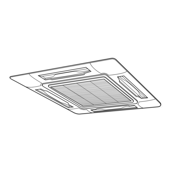
4-way Air Discharge Cassette type
Concealed Duct type
Under Ceiling type
High wall type
SPLIT TYPE
RAV-SP1100UT-E
Indoor unit
Service Manual No.
RAV-SM560UT-E
RAV-SM800UT-E
RAV-SM1400UT-E
RAV-SM561BT-E
RAV-SM801BT-E
RAV-SM1101BT-E
RAV-SM1401BT-E
RAV-SM561CT-E
RAV-SM801CT-E
RAV-SM1101CT-E
RAV-SM1401CT-E
RAV-SM560KRT-E
RAV-SM800KRT-E
PRINTED IN JAPAN, Feb.,2004 ToMo
FILE NO. A03-013
A02-013
A02-013
A03-003
A03-007
A03-007
A03-007
A03-007
A03-015
A03-015
A03-015
A03-015
A02-013
A02-013
Advertisement
Table of Contents

Related Manuals for Toshiba RAV-SP1100UT-E


Summary of Contents for Toshiba RAV-SP1100UT-E
-
Page 1: Service Manual
RAV-SP1100AT-E, RAV-SP1400AT-E R410A The type of all the indoor units described in this Service Manual is a new model, RAV-SP1100UT-E only. For the other indoor units to be combined, refer to the Service Manuals for the following models. Indoor unit Service Manual No. - Page 2 ADOPTION OF NEW REFRIGERANT This Air Conditioner is a new type which adopts a new refrigerant HFC (R410A) instead of the conventional refrigerant R22 in order to prevent destruction of the ozone layer. WARNING Cleaning of the air filter and other parts of the air filter involves dangerous work in high places, so be sure to have a service person do it.
-
Page 3: Table Of Contents
Indoor Unit (4-Way Air Discharge Cassette Type) –––––––––––––––––––––––– RAV-SP1100UT-E OWNWE’S MANUAL ACCESSORIES (SOLD SEPARATELY) ....... 4 ADJUSTMENT OF WIND DIRECTIONd ......11 PRECAUTIONS FOR SAFETY ..........4 TIMER OPERATION ............12 PARTS NAME ............... 6 MAINTENANCE ..............14 PARTS NAME OF REMOTE CONTROLLER ....... 7 AIR CONDITIONER OPERATIONS AND PERFORMANCE ... -
Page 4: Precautions For Safety
PRECAUTIONS FOR SAFETY • Ensure that all Local, National and International regulations are satisfied. • Read this “PRECAUTIONS FOR SAFETY” carefully before Installation. • The precautions described below include the important items regarding safety. Observe them without fail. • After the installation work, perform a trial operation to check for any problem. Follow the Owner’s Manual to explain how to use and maintain the unit to the customer. -
Page 5: Accessory And Refrigerant
• When the air conditioner is installed in a small room, provide appropriate measures to ensure that the concentration of refrigerant leakage occur in the room does not exceed the critical level. • Install the air conditioner securely in a location where the base can sustain the weight adequately. •... -
Page 6: Selection Of Installation
SELECTION OF INSTALLATION <SP560AT-E> CAUTION Length of refrigerant pipe <SP560AT-E, SP800AT-E only> connected to Item indoor/outdoor unit When using an air conditioner under low outside Addition of refrigerant is temperature condition (Outside temp.:–5°C or 20m or shorter unnecessary at the local site. lower) with COOL mode, prepare a duct or wind <Addition of refrigerant>... - Page 7 Installation Place Necessary Space for Installation • A place which provides a specified space around the Obstacle at rear side outdoor unit. • A place where the operation noise and discharged air <Upper side is free> are not given to your neighbors. 1.
- Page 8 SELECTION OF INSTALLATION <Obstacle also at the upper side> Installation of Outdoor Unit • Before installation, check strength and horizontality of the base so that abnormal sound does not generate. 1000 or more • According to the following base diagram, fix the base firmly with the anchor bolts.
-
Page 9: Refrigerant Piping Connection
<SM560AT-E> Refrigerant Piping Connection CAUTION TAKE NOTICE THESE IMPORTANT Waterproof rubber cap 4 POINTS BELOW FOR PIPING WORK 1. Keep dust and moisture away from inside the connecting pipes. 2. Tightly connect the connection between pipes Base plate and the unit. 3. - Page 10 SELECTION OF INSTALLATION How to remove the front panel Knockout of Pipe Cover 1. Remove screws of the front panel. <SM800AT-E, SP560AT-E, SP800AT-E> 2. Pull the front panel downward. Removing the front panel, the electric parts appear at the front side. •...
-
Page 11: Refrigerant Piping
REFRIGERANT PIPING • Flaring size : A (Unit : mm) Pipe Forming/End Positioning <SM560AT-E> - 0.4 Outer diam. of copper pipe • Forming of pipe R410A Form the pipe along with a marked line of the cabinet. 6.35 • End positioning of pipe 9.52 13.2 13.0... - Page 12 REFRIGERANT PIPING Tightening of Connecting Part REQUIREMENT (Unit: N•m) 1. Do not put the spanner on the cap. The valve may be broken. Outer diam. of copper pipe Tightening torque 2. If applying excessive torque, the nut may be 6.35mm (diam.) 14 to 18 (1.4 to 1.8kgf•m) broken according to some installation conditions.
-
Page 13: Air Purge
EVACUATING Air Purge This air conditioner can be installed up to the connecting pipe length and height difference in the following table. Height difference (m) Max. connecting Hexagonal Capacity rank pipe length (m) wrench size Outdoor unit at upper side Outdoor unit at lower side SM560 type SM800, SP560, SP800 type... - Page 14 EVACUATING <SM560AT-E> How to open the valve Compound pressure gauge Pressure gauge Valve unit –101kPa (–76cmHg) Manifold valve Handle Lo Handle Hi (Keep fully closed) Handle Pull out the handle and Charge hose Charge hose using cutting pliers, etc. (For R410A only) (For R410A only) turn it counterclockwise by 90˚.
-
Page 15: Electrical Work
ELECTRICAL WORK For the air conditioner that has no power cable, connect How to wire a power cable as mentioned below. 1. Connect the connecting cable to the terminal as identified with their respective numbers on the SM800AT-E terminal block of indoor and outdoor unit. Model RAV- SM560AT-E... -
Page 16: Installation Manual
FINAL INSTALLATION CHECKS Check and Test Operation Valve cover For R410A, use the leak detector exclusively manufactured for HFC refrigerant (R410A, R134a, etc.). Piping The conventional leak detector for HCFC refrigerant (R22, cover etc.) cannot be used because its sensitivity for HFC refrigerant lowers to approx. -
Page 17: Installation/Servicing Tools
Installation/Servicing Tools Changes in the product and components In the case of an air conditioner using R410A, in order to prevent any other refrigerant from being charged acciden- tally, service port diameter of the outdoor unit control valve (3 way valve) has been changed. (1/2 UNF 20 threads per inch) •... -
Page 18: Precautions For Safety
PRECAUTIONS FOR SAFETY • Ensure that all Local, National and International regulations are satisfied. • Read this “PRECAUTIONS FOR SAFETY” carefully before Installation. • The precautions described below include the important items regarding safety. Observe them without fail. • After the installation work, perform a trial operation to check for any problem. Follow the Owner’s Manual to explain how to use and maintain the unit to the customer. -
Page 19: Accessory And Refrigerant
• When the air conditioner is installed in a small room, provide appropriate measures to ensure that the concentration of refrigerant leakage occur in the room does not exceed the critical level. • Install the air conditioner securely in a location where the base can sustain the weight adequately. •... -
Page 20: Selection Of Installation
SELECTION OF INSTALLATION CAUTION <SP1100AT-E, SP1400AT-E only> When using an air conditioner under low outside temperature condition (Outside temp.:–5°C or lower) with COOL mode, prepare a duct or wind shield so that it is not affected by the wind. <Example> Discharge upward/downward Suction hood (Side) or leftward is also available. - Page 21 Installation Place Necessary Space for Installation • A place which provides a specified space around the Obstacle at rear side outdoor unit. • A place where the operation noise and discharged air <Upper side is free> are not given to your neighbors. 1.
-
Page 22: Selection Of Installation
SELECTION OF INSTALLATION <Obstacle also at the upper side> Installation of Outdoor Unit • Before installation, check strength and horizontality of the base so that abnormal sound does not generate. 1000 or more • According to the following base diagram, fix the base firmly with the anchor bolts. -
Page 23: Refrigerant Piping
Optional Installation Parts Knockout of Pipe Cover (Local Procure) Parts name Q’ty Refrigerant piping Liquid side : Ø9.5 mm Each one Gas side : Ø15.9 mm Pipe insulating material (polyethylene foam, 6 mm thick) Rear direction Putty, PVC tapes Each one Pipe cover Side direction Front direction... - Page 24 SELECTION OF INSTALLATION In order to avoid the force applied to on the connect- How to remove the front panel ing section, be sure to fix the cables to the cord 1. Remove screws of the front panel. clamps provided on the pipe valve fixing plate and the electric parts box.
- Page 25 REFRIGERANT PIPING Tightening of Connecting Part REQUIREMENT (Unit: N•m) 1. Do not put the spanner on the cap. The valve may be broken. Outer dia. of copper pipe Tightening torque 2. If applying excessive torque, the nut may be 6.4 mm (diam.) 14 to 18 (1.4 to 1.8 kgf•m) broken according to some installation conditions.
- Page 26 EVACUATING Air Purge This air conditioner can be installed up to the connecting pipe length and height difference in the following table. Height difference (m) Max. connecting Hexagonal Capacity rank wrench size pipe length (m) Outdoor unit at upper side Outdoor unit at lower side SM1100, SM1400 type SP1100, SP1400 type...
- Page 27 Handle position Compound pressure gauge Pressure gauge –101kPa (–76cmHg) Manifold valve Handle Lo Handle Hi (Keep fully closed) Charge hose (For R410A only) Charge hose (For R410A only) Service port Handle (Valve core (Setting pin)) Vacuum pump adapter for counter-flow prevention Closed completely Opened fully (For R410A only)
-
Page 28: Electrical Work
ELECTRICAL WORK For the air conditioner that has no power cable, connect Stripping length power cord and connecting cable a power cable as mentioned below. SM1400AT-E Model RAV- SM1100AT-E SP1100AT-E 1 2 3 SP1400AT-E 220 – 240 V Power supply Single phase 50 Hz Maximum running current 22.0 A... -
Page 29: Final Installation Checks
FINAL INSTALLATION CHECKS Check and Test Operation For R410A, use the leak detector exclusively manufactured for HFC refrigerant (R410A, R134a, etc.). The conventional leak detector for HCFC refrigerant (R22, etc.) cannot be used because its sensitivity for HFC refrigerant lowers to approx. 1/40. •... -
Page 30: Final Installation Checks
FINAL INSTALLATION CHECKS Installation/Servicing Tools Changes in the product and components In the case of an air conditioner using R410A, in order to prevent any other refrigerant from being charged acciden- tally, service port diameter of the outdoor unit control valve (3 way valve) has been changed. (1/2 UNF 20 threads per inch) •...
Need help?
Do you have a question about the RAV-SP1100UT-E and is the answer not in the manual?
Questions and answers