Table of Contents
Advertisement
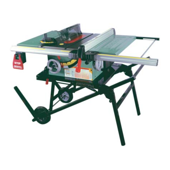
SETUP & OPERATION MANUAL
FEATURES
50-090RK: JOB SITE SAW, INCLUDES
50-090R SAW AND FOLDING STAND
#50-095.
50-090RC: CONTRACTOR SAW, INCLUDES
50-090R SAW AND FIXED LEG STEEL STAND
#50-096.
Heavy-duty, precision cast-iron, ribbed table
with miter gauge t-slots.
2 1/2" dust port allows easy connection
to a dust collection system.
Deluxe, quick adjusting miter gauge.
Ruggedly built saw carriage.
Arbor driven by a two step belt, ensuring
straightness and accuracy when the blade
is tilted.
Heavy-duty folding stand with wheels for
easy mobility and storage (50-090RK M1).
Sturdy open base steel stand (50-090RC M1).
Combination riving style splitter and see
through blade guard with anti-kickback
pawls, and a second European style riving
knife also included.
Includes new Excalibur aluminum T-fence
style precision rip fence system.
Smooth running belt driven 2 HP induction
motor for quiet start-up and operation, and
longer running life.
Large paddle-style stop switch.
SPECIFICATIONS
BLADE DIAMETER
10'' (254 mm)
ARBOR DIAMETER
5 ⁄
" (16 mm)
8
MAXIMUM DEPTH OF CUT AT 90°
1 ⁄
3
" (83 mm)
4
MAXIMUM DEPTH OF CUT AT 45°
5 ⁄
2
'' (59 mm)
16
MAXIMUM RIP TO RIGHT OF BLADE
36'' (914 mm)
DADO CAPACITY
3 ⁄
" (19 mm)
4
ARBOR SPEED
3450 RPM
TABLE SIZE (W/O EXTENSION WINGS)
1 ⁄
20'' x 25
" (508 x 641 mm)
4
EXTENSION WINGS SIZE (2)
1 ⁄
10" x 25
" (254 x 641 mm)
4
DUST PORT DIAMETER
1 ⁄
2
" (64 mm)
2
OVERALL DIMENSIONS (L X W X H)
1 ⁄
69" x 38" x 42
" (1745 x 965 x 1080 mm)
2
1 ⁄
1 ⁄
66
" x 38" x 43
" (1690 x 965 x 1150 mm)
2
2
MOTOR (PRE-WIRED 110 V)
2 HP , 110 / 220 V, 13/6.5 A
WEIGHT
233 LBS (106 kg)
- 50-090RK
217 LBS (98.5 kg)
- 50-090RC
10" JOB SITE SAW /
CONTRACTOR SAW
- Left tilt with riving knife
MODEL
# 50-090RK M1
#50-090RC M1
- 50-090RK
- 50-090RC
VERSION 1_REVISION 1 - August 17/11
© Copyright General® International 08/2011
Advertisement
Table of Contents

Related Manuals for General 50-090RK MI


Summary of Contents for General 50-090RK MI
-
Page 1: Specifications
” (1690 x 965 x 1150 mm) - 50-090RC MOTOR (PRE-WIRED 110 V) 2 HP , 110 / 220 V, 13/6.5 A WEIGHT 233 LBS (106 kg) - 50-090RK 217 LBS (98.5 kg) - 50-090RC VERSION 1_REVISION 1 - August 17/11 © Copyright General® International 08/2011... - Page 2 Because of our commit- ment to quality and customer satisfaction, General® International agrees to repair or replace, within a period of 24 months from date of purchase, any genuine part or parts which, upon examination, prove to be defective in work- manship or material.
- Page 3 Warranty does not include failures, breakage or defects deemed after inspection by General® MFG or General® International to have been directly or indirectly caused by or resulting from; improper use, or lack of or improper maintenance, misuse or abuse, negligence, accidents, damage in handling or transport, or normal wear and tear of any generally considered con- sumable parts or components.
-
Page 4: Table Of Contents
TABLE OF CONTENTS SAFETY RULES ..... . . Align and level the rip fence ... . . Align the rip fence parallel to the blade . - Page 5 To help ensure safe operation, please take a moment to learn the machine’s applications and limitations, as well as poten- tial hazards. General® International disclaims any real or implied warranty and holds itself harmless for any injury that may result from improper use of its equipment.
-
Page 6: Electrical Requirements
In the event of an electrical malfunction or short cir- We suggest you ask your local General International cuit, grounding reduces the risk of electric shock. The distributor to recommend qualified electricians in your... -
Page 7: Identification Of Main Parts And Components
10” JOB SITE SAW / CONTRATOR SAW 50-090RK M1 or 50-090RC M1 (left tilt with riving knife) IDENTIFICATION OF MAIN PARTS AND COMPONENTS 50-090RC M1 50-090RK M1 A- LEFT TABLE EXTENSION G- REAR RAIL M- MITER GAUGE STORAGE BRACKET B- MITER GAUGE H- FRONT RAIL N- ON/OFF SWITCH C- MAIN TABLE... -
Page 8: Unpacking & Set Up
Carefully unpack and remove the unit and its components from its shipping containers and check for missing or damaged items as per the list contents below. LIST OF CONTENTS Note: Please report any damaged or missing items to your General International distributor immediately. BOX #1 Model 50-090R M1: Saw only... -
Page 9: Placement Within The Shop / Establishing Asafety Zone
PLACEMENT WITHIN THE SHOP / ESTABLISHING A SAFETY ZONE 50-090RK M1 38” THIS MODEL IS HEAVY. DO NOT OVER-EXERT. A HOIST OR FORKLIFT WITH STRAPS SHOULD BE USED TO LIFT THIS MACHINE. TO LIMIT THE RISK OF SERIOUS INJURY OR DAMAGE TO THE MACHINE, ANY 42 ½”... -
Page 10: Assembly Instructions
ASSEMBLY INSTRUCTIONS SERIOUS PERSONAL INJURY COULD OCCUR IF YOU CONNECT THE MACHINE TO THE POWER SOURCE BEFORE YOU HAVE COMPLETED THE INSTALLATION AND ASSEMBLY STEPS. DO NOT CONNECT THE MACHINE TO THE POWER SOURCE UNTIL INSTRUCTED TO DO SO. ASSEMBLE THE FOLDING STAND (50-095 SUPPLIED WITH 50-090RK M1 ONLY) The folding stand comes partially assembled. -
Page 11: Assemble The Fixed Leg Stand (#50-096)
7. To access the 2 pistons tilt the stand forward onto its 8. Using a 1/2” socket and 1/2” or adjustable wrench vertical support legs as shown. secure the 2 pistons to the stand frame using the bolt, washer, spacer & nut in the sequence shown. ASSEMBLE THE FIXED LEG STAND (50-096 SUPPLIED WITH 50-090RC M1 ONLY) To assemble the fixed leg stand assembly follow the steps listed below. -
Page 12: Assemble The Saw
5. Attach the front and rear top shelves as shown 6. Attach the two side top shelves as shown using using 4 carriage bolts, flat washers and hex nuts for 4 carriage bolts, flat washers and hex nuts for each each cross brace. -
Page 13: Assemble The Front Fence Rails
Attach the steel table extension wings to the main table as shown using 8 12mm hex head bolts (4 per wing) and level here 8 lock washers. Align the table extensions with the table and loosely attach the bolts. Place a straight edge on the table and extension as shown to align the extension table and then tighten down the bolts. -
Page 14: Assemble The Rear Fence Rails
ASSEMBLE THE REAR FENCE RAILS Use 6 cap screws with lock washers and nuts A to assemble the rear rails to the rear of the saw as shown B. Make sure that the intersection C between the two rear rails is leveled D. MOUNT THE SWITCH 12"... -
Page 15: Install / Remove A Saw Blade
INSTALL / REMOVE A SAW BLADE BE SURE THE SAW IS UNPLUGGED AND COMPLETELY DISCONNECTED FROM THE POWER SOURCE WHEN- EVER INSTALLING OR REMOVING A SAW BLADE! Loosen the retaining screw and remove the table insert plate, A. Install a saw blade (not supplied with the saw) so that the openings between the teeth face the front of the saw (the blade spins in the counter-clockwise direction). -
Page 16: Removal/Installation
REMOVAL/INSTALLATION Set the blade to 90º and raise it to its highest position and remove the table insert. If already installed, remove the splitter or riving knife by loosening the lock knob A and pulling the splitter or riving knife up out of its mounting bracket. -
Page 17: Install
INSTALL Align the pins on the blade cover with the 2 hooks Slip the cover down onto the splitter 1, push it back A on the splitter. into the hooks 2 and then tighten the lock knob B. REMOVE/INSTALL ANTI-KICKBACK PAWLS Disconnect the machine from the power source. -
Page 18: Align And Level The Rip Fence 5
ALIGN AND LEVEL THE RIP FENCE THE RIP FENCE MUST BE PARALLEL TO THE BLADE DU- RING OPERATION. FAILURE TO SET THE RIP FENCE PA- RALLEL TO THE BLADE CAN RESULT IN KICKBACK AND POSSIBLE SERIOUS INJURY. ALIGN THE RIP FENCE PARALLEL TO THE BLADE To make satisfactory rip cuts, your fence must be aligned perfectly parallel with the saw blade. -
Page 19: Adjust & Align Rip Fence Pointer
50-090RK M1 • If you do not already own a dust collection system consider contacting your General® International dis- tributor for information on our complete line of dust col- lection systems and accessories or visit our website at www.general.ca... -
Page 20: On / Off Switch And Safety Pin
ON/OFF SWITCH & SAFETY PIN The switch assembly is equipped with a lock-out safety pin. When the pin is installed through the green “ON” but- ton, the machine cannot be started. To start the machine, lift the red “STOP” switch panel and remove the lock-out pin. -
Page 21: Bevel Ripping
As you complete the rip, the wood will either remain on the table, tilt up to be caught on the end of the guard, or fall onto the floor (or outfeed table). The waste part of the stock remains on the table to be removed only after the saw is stopped (unless it is large enough for immediate safe removal). -
Page 22: Adjusting And Using The Miter Gauge 9
BEVEL CROSS CUTTING This procedure is the same as cross cutting except that the blade is set to an angle other than 0. After changing the bevel angle, verify the alignment of the guard and splitter and verify that there is clea-rance with the saw blade. -
Page 23: Miter Cuts
Marking Wood. If you measure a cut for 24 inches, line up the blade on the waste side of the mark. Don’t cut through the middle of the measurement line or you’ll reduce your desired board length by half the width of the saw blade! For accurate work, don’t mark your cut with a fat pencil line, G. -
Page 24: Recommended Optional Accessories
RECOMMENDED OPTIONAL ACCESSORIES We offer a large variety of products to help you increase convenience, productivity, accuracy and safety when using your saw. Here’s a small sampling of optional accessories available from your local General International dealer. For more information about our products, please visit our website at www.general.ca... - Page 25 MACHINE...
- Page 26 PARTS LIST 50-090R REF. IN PART N0. DESCRIPTION SPECIFICATION DIAGRAM 50090-01 TABLE EXTENSION 50090R-01 TABLE 50090-02 PLASTIC INSERT PLATE (ALIGN-A-CUT) 50090R-03 FIXED BUTTON 50090-05 SET SCREW M8 X 1.25P X 20 50090R-04 SET SCREW M5 X 0.8P X 12 50090R-05 TABLE INSERT 50090-08 SPRING WASHER...
- Page 27 FENCE & RAIL ASSEMBLY...
- Page 28 PARTS LIST 50-090R REF. IN PART N0. DESCRIPTION SPECIFICATION DIAGRAM 50221-34 COMPLETE RIP FENCE 50221-35 FENCE END CAP 50221-36 CONNECTION PLATE 50090R-18 HEXAGONAL HEAD SCREW M6 X 1.0P X 45 50221-38 LOCK PLATE 50221-39 PLASTIC PAD (SLIDER) 50221-40 SCREW 50221-41 POINTER ASSEMBLY 50090R-19 POINTER...
-
Page 29: Tilting Mechanism
TILTING MECHANISM PARTS LIST 50-090R REF. IN PART N0. DESCRIPTION SPECIFICATION DIAGRAM 50090R-26 BELT 735LI-13X 50090R-27 TIMING BELT 125J-6 50090R-28 PULLEY 50090-100 SNAP RING STW-15 50090-101 BEARING 6002-2NSE 50090R-31 FLAT WASHER 6.4 X 20 X 3.0T 50090R-29 LONG SHAFT 50090R-30 SHAFT GEAR 50090R-31 SET SCREW... - Page 30 PARTS LIST 50-090R REF. IN PART N0. DESCRIPTION SPECIFICATION DIAGRAM 50090-118 WAVE WASHER WW-16 50090-119 O RING 50090-120 SNAP RING ETW-12 50090-121 ELEVATION GEAR SHAFT 50090-122 MOUNTING BRACKET 50090R-38 CAP SCREW M5 X 0.8P X 12 50090-124 SPACING COLLAR 50090-125 HANDWHEEL 50090-126 LOCK KNOB...
- Page 31 BLADE GUARD PARTS LIST 50-090R REF. IN PART N0. DESCRIPTION SPECIFICATION DIAGRAM 50221-180 SPLITTER / BLADE GUARD ASSEMBLY TH25 50221-181 LEFT LOWER GUARD 50221-182 LOCK NUT M5 X 0.8P(8B X 6H) 50221-183 BOLT M5 X 0.8P X 15 50221-184 LEFT UPPER GUARD 50221-185 PIVOT PIN 50221-186...
-
Page 32: Miter Gauge
MITER GAUGE PARTS LIST 50-090R REF. IN PART N0. DESCRIPTION SPECIFICATION DIAGRAM 50221-173 MITER GAUGE COMPLETE 50090-169 HANDLE 50090-170 FLAT WASHER 8.5 X 16 X 2.0T 50090-171 MITER GAUGE BODY 50090-172 PHILLIPS HEAD SCREW M4 X 0.7P X 20 50090-173 M4 X 0.7P(7B X 3.2H) 50090-174 PHILLIPS HEAD SCREW... - Page 33 FOLDING STAND # 50-095 (50-090RK ONLY) PARTS LIST 50-095 REF. IN PART N0. REF. N0. DESCRIPTION SPECIFICATION DIAGRAM 50095-183 340077-000 WHEEL 50095-184 006001-090 FLAT WASHER 12.2 X 22 X 2.0T 50095-185 010207-000 SNAP RING ETW-10 50095-186 360536-901 AXLE 50095-187 250519-615 END CAP 50095-188 171698-008...
- Page 34 PARTS LIST 50-095 REF. IN PART N0. REF. N0. DESCRIPTION SPECIFICATION DIAGRAM 50095-190 006001-029 FLAT WASHER 6.5 X 23 X 3.0T 50095-191 340007-615 50095-192 008311-100 LOCK NUT M12 X 1.75P 50095-193 000002-313 HEX HEAD BOLT M6 X 1.0P X 70 50095-194 171699-008 MAIN SUPPORT BRACKET...
- Page 35 FIXED LEG STAND # 50-096 (50-090RC ONLY) PARTS LIST 50-096 REF. IN PART N0. REF. NO. DESCRIPTION SPECIFICATION DIAGRAM 50090R-60 STAND COMPLETE 50090R-61 000003-204 HEX. HEAD BOLT M8 X 1.25P X 20 50090R-62 006002-049 FLAT WASHER 8.5 X 16 X 2.0T 50090R-63 008006-200 HEX.
- Page 36 Fax : (514) 326-5565 Parts & Service Fax : (514) 326-5555 Order Desk orderdesk@general.ca www.general.ca IMPORTANT: When ordering replacement parts, always give the model number, serial number of the machine and part number. Also a brief description of each item and quantity...
Need help?
Do you have a question about the 50-090RK MI and is the answer not in the manual?
Questions and answers