Table of Contents
Advertisement
Quick Links
SETUP & OPERATION MANUAL
FEATURES
Cast-iron frame & precision-balanced alu-
minum wheels with replaceable rubber
tires.
Sturdy, easy to assemble, open base steel
stand.
Precision aluminum miter gauge with han-
dle.
2 cutting speeds for excellent results in
either hard or soft woods.
Hinged door and easily accessible blade
tension knob, for fast blade changes or
adjustments.
Ball-bearing and carbon block blade
guide assembly.
Built-in blade cleaning brush keeps tires
free of dust and chips.
Safety lock-out switch with removable key
to prevent unauthorized use.
SPECIFICATIONS
WHEEL SIZE
13 7⁄8 " (353 mm)
WHEEL SPEEDS (2)
470/820 RPM
MAXIMUM BLADE WIDTH
3⁄4" (19 mm)
MINIMUM BLADE WIDTH
1⁄4" (6 mm)
BLADE LENGTH
93 1⁄2" (2375 mm)
BLADE SPEEDS (2)
1630 & 2730 LIN. FPM (495/832 LIN. MPM)
TABLE SIZE
16" x 16" (406 x 406 mm)
TABLE TILT
0°- 45° (RIGHT) / 0°-10° (LEFT)
TABLE HEIGHT
42" (1067 mm)
MAXIMUM WIDTH OF CUT
13 1⁄2" (343 mm)
MAXIMUM DEPTH OF CUT
6" (150 mm)
DUST COLLECTION PORT
2 1⁄2" (63 mm)
BASE DIMENSIONS (L x W x H)
27 3⁄16" x 20 1/2" x 22"
(690 x 520 x 560 mm)
MOTOR
1 HP , 110 V, 1 PH, 10 A
WEIGHT (SHIIPING/NET)
185 LBS (84 kg) / 176 LBS (80 KG)
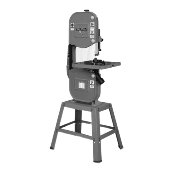
14" WOOD CUTTING BANDSAW
MODEL
# 90-140 SM1
VERSION 1_REVISION 1 - October 15, 2013
© Copyright General® International 10/2013
Advertisement
Table of Contents

Subscribe to Our Youtube Channel
Related Manuals for General 90-140 SM1


Summary of Contents for General 90-140 SM1
- Page 1 27 3⁄16” x 20 1/2” x 22” (690 x 520 x 560 mm) MOTOR 1 HP , 110 V, 1 PH, 10 A WEIGHT (SHIIPING/NET) 185 LBS (84 kg) / 176 LBS (80 KG) VERSION 1_REVISION 1 - October 15, 2013 © Copyright General® International 10/2013...
- Page 2 GENERAL® INTERNATIONAL 8360 Champ-d’Eau, Montreal (Quebec) Canada H1P 1Y3 Telephone (514) 326-1161 • Fax (514) 326-5555 • www.general.ca THANK YOU for choosing this General ® International Star-Shop model 90-140 SM1 14” Wood Cutting Bandsaw. This bandsaw has been carefully tested and inspected before ship- ment and if properly used and maintained, will provide you with years of reliable service.
- Page 3 2 years (24 months) from the date of purchase. General® and General® International agree to repair or replace any part or component which upon examination, proves to be defective in either workmanship or material to the original purchaser during this 2-year warranty period, subject to the “conditions...
-
Page 4: Table Of Contents
TABLE OF CONTENTS Rules for safe operation ....Blade clearance ......14-15 Electrical requirements . -
Page 5: Rules For Safe Operation
To help ensure safe operation, please take a moment to learn the machine’s applications and limita- tions, as well as potential hazards. General® International disclaims any real or implied warranty and hold itself harmless for any injury that may result from the improper use of it’s equipment. -
Page 6: Electrical Requirements
ELECTRICAL REQUIREMENTS BEFORE CONNECTING THE MACHINE TO THE POWER SOURCE, VERIFY THAT THE VOLTAGE OF YOUR POWER SUPPLY CORRESPONDS WITH THE VOLTAGE SPECIFIED ON THE MOTOR I.D. NAMEPLATE. A POWER SOURCE WITH GREATER VOLTAGE THAN NEEDED CAN RESULT IN SERIOUS INJURY TO THE USER AS WELL AS DAMAGE TO THE MACHINE. IF IN DOUBT, CONTACT A QUALIFIED ELECTRICIAN BEFORE CONNECTING TO THE POWER SOURCE. -
Page 7: Identification Of Main Parts And
IDENTIFICATION OF MAIN PARTS AND COMPONENTS FRONT VIEW BLADE TENSION ADJUSTMENT KNOB BLADE GUARD LOCK KNOB UPPER BLADE GUIDE ASSEMBLY BLADE GUARD MITER GAUGE TABLE ALIGNMENT PIN DUST PORT STAND TABLE TILT LOCK KNOB LOWER WHEEL COVER DOOR ON/OFF SWITCH W/SAFETY KEY UPPER WHEEL COVER DOOR REAR VIEW BLADE TRACKING ADJUSTMENT KNOB... -
Page 8: Unpacking
Carefully unpack and remove the unit and its components from its shipping container and check for missing or damaged items as per the list of contents below. NOTE: Please report any damaged or missing items to your GENERAL® INTERNATIONAL distributor immediately. LIST OF CONTENTS... -
Page 9: Basic Functions Of The Unit
“Recommended Optional Accessories for your Bandsaw”. PLACEMENT WITHIN THE SHOP / ESTABLISHING A SAFETY ZONE THIS MODEL 90-140 SM1 BANDSAW IS HEAVY (176 LBS - 80 KG). DO NOT OVER-EXERT. THE HELP OF AN ASSISTANT WILL BE NEEDED FOR THE FOLLOWING STEP . -
Page 10: Assembly Instructions
ASSEMBLY INSTRUCTIONS SERIOUS PERSONAL INJURY COULD OCCUR IF YOU CONNECT THE MACHINE TO THE POWER SOURCE BEFORE YOU HAVE COMPLETED THE INSTALLATION AND ASSEMBLY STEPS. DO NOT CONNECT THE MACHINE TO THE POWER SOURCE UNTIL INSTRUCTED TO DO SO. ASSEMBLING THE STAND Lay the top plate A upside down on a flat surface. -
Page 11: Attaching The Dust Port
ATTACHING THE DUST PORT The dust port A has a 2 –1/2" opening to accommodate connection to a dust collector (not included). Install the dust outlet on the right side of the bandsaw as follows: Open the lower wheel cover door. Using a 10 mm wrench, attach the dust port to the edge of the door as shown using the hex bolts and washers B already attached to the dust port. -
Page 12: Miter Gauge
Carefully move the table into position over the Gently lower the table onto the bracket so the table-tilt bracket, guiding the saw blade through long bolts C in the center of the trunnions pass the table slot D. through the holes in the table-tilt bracket. Note: If the long bolts have moved out of position, have an Rotate the table 1/4 turn counter-clockwise so that assistant tap them into place with a screw driver. -
Page 13: Basic Adjustments And Controls
BASIC ADJUSTMENTS AND CONTROLS CONNECTING TO A POWER SOURCE To avoid risk of shock or fire do not operate the unit with a damaged power cord or plug. Replace damaged cord or plug immediately. To avoid unexpected or unintentional start-up, make sure that the power switch is in the the OFF position before connecting to a power SWITCH «OFF»... -
Page 14: Tilting The Table
Adjust the height of the table-stop bolt until it tou- With the table set to 90º and the stop bolt at the correct height, make sure the table tilt angle indi- ches the underside of the table D. cator pointer H is set to read 0º. Turn the jam-nut E clockwise until it meets the table tilt-bracket F and tighten it. -
Page 15: To Remove A Blade
Move the upper thrust bearing back: Loosen the upper thumb screw D. Use the micro adjust nut E to move the thrust bearing F back as far as possible behind the blade. Move the lower guide blocks / thrust bearing away from the blade: Loosen the two set screws G using the supplied 3 mm Allen key. -
Page 16: Blade Selection
Standard size - 93 1⁄2” (2375 mm) - replacement blades made from high carbon steel can be purchased in a variety of widths from your General® International dealer under the following parts numbers: • #90125-B14:1/4” - 6 TPI, blade thickness: 0.65 mm •... -
Page 17: Adjusting Blade Tension
When working with narrower blades, sawing shorter stock and making tighter curved cuts are best per- formed using less tension This model 90-140 SM1 bandsaw is equipped with a blade tension scale, which can be used as a reference for the ideal setting with various blade widths. -
Page 18: Adjusting The Blade Guard For Depth Of Cut
When adjusting blade tracking to center the blade on the wheels and assuming that 3 mm - 1/8" perfect centering is not attainable, it is preferable to have the blade slightly off-center towards the front of the wheels rather than towards the rear because the teeth on most bandsaw blades have alternating hook (one inner, one outer) –... -
Page 19: Adjusting The Upper Guide Blocks And Thrust Bearing
ADJUSTING THE UPPER GUIDES BLOCKS AND THRUST BEARING Note: Before adjusting the upper and lower blade guides and thrust bearings, make sure the blade is tensioned and track- ing properly. Adjust the upper and lower blade guides and thrust bearings after each blade tension and tracking adjust- ment. -
Page 20: Positioning The Lower Guide Blocks And Thrust Bearing
POSITIONING THE LOWER GUIDE BLOCKS AND THRUST BEARING The lower blade guide blocks and thrust bearing perform the same function as the upper blade guide blocks and thrust bearing except they do so after the blade has contacted the stock being cut. Repeat steps 1 to 4 of section “Adjust the positioning of the upper blade guides blocks”... -
Page 21: Operating Instructions
Make sure all the blade guards are in place. Make sure the bandsaw table and work area in general are clean and free of sawdust and debris. These steps should always be followed when any adjustment is performed, the blade is changed, or periodically as vibra- tion and normal wear and tear on the machine could throw these parts out of alignment. -
Page 22: To Stop The Machine
TO STOP THE MACHINE 1. Push the red tab down and remove the yellow key. 2. Turn your dust collector off. USING THE MITER GAUGE The miter gauge allows for easier and safer sawing by providing workpiece support when cutting straight (90°) or angled ends (0°... -
Page 23: Periodic Maintenance & Lubrication
PERIODIC MAINTENANCE & LUBRICATION Disconnect machine from power source, before performing any lubrication or maintenance. LUBRICATION Keep the rack and pinion A as well as the blade tension adjustment screw B well greased and free of dust or debris. Clean and remove dust, debris, and old grease after every 10-15 hours of use. -
Page 24: Replacing The Upper And Lower Thrust Bearing
REPLACING THE UPPER AND LOWER THRUST BEARINGS Turn the tension knob A counter-clockwise for the blade to be loose enough to remove easily. Remove the right hand side blade guard B by loos- ening the two phillips head screws C, just enough to slide it out. -
Page 25: Replacing Lower Wheel Motor Belt
Verify that the brush keeps the lower wheel surface clean at all times. With use and normal wear over time, the brush hairs will soften and will not clean the surface of the wheel as well. You then must lower the brush slightly. Proceed as follows: 1. -
Page 26: Recommended Optional Accessories
We offer a large variety of products for increased convenience, productivity, accuracy and safety when using your bandsaw.. Here’s a small sampling of optional accessories available from your local General International dealer. For more information about our products, please visit our website at www.general.ca... - Page 27 FRAME ASSEMBLY...
- Page 28 WHEEL AND TABLE ASSEMBLY 44 52...
- Page 29 PARTS LIST 90-140S M1 REF # PART. N0. DESCRIPTION SPECIFICATION QTY 90140-01 UPPER FRAME WA-14CD 90125-50 UPPER BLADE GUIDE LOCK KNOB 5/16" X 1-1/4" 90125-46 HEX. NUT 3/16" 90140-02 GUIDE POST (V TYPE) 90125-54 UPPER BLADE GUIDE HOLDER WA-14 90125-123 THUMB SCREW M6 X 10L 90125-56...
- Page 30 PARTS LIST 90-140S M1 REF # PART. N0. DESCRIPTION SPECIFICATION QTY 90125-70 LOWER BLADE GUIDE HOLDER WA-14 90125-55 SET SCREW M6 X 10L 90125-43 DOOR HINGE WA-14C 90125-67 PHILLIPS HEAD SCREW 3/16" X 3/8" 90125-118 STEEL PLATE 90125-119 FLANGE SCREW 3/16"...
- Page 31 PARTS LIST 90-140 SM1 REF # PART. N0. DESCRIPTION SPECIFICATION QTY 90125-128 MITER GAUGE BS3550PC 90140-16 BLADE GUIDE MOUNT WA-14 90125-66 FLAT WASHER 3/16" X 14 90140-17 FLAT WASHER 1/4" X 13 X 1.5T 90125-53 SET SCREW 5/16 X 5/16"...
- Page 32 MOTOR REF. # PART N0. DESCRIPTION SPECIFICATION QTY 90140-23 SHAFT 95 X 50 X 282L X Ø14 90125-106A-02 ROTOR 95 X 50 X Ø20 90140-24 STATOR 160 X 95 X 50 90140-25 COPPER WINDING 0.75(1.558KG) 90125-106A-06 BEARING 6202ZZ 90125-106A-07 BEARING 6203ZZ 90125-106A-08 FRONT MOTOR COVER...
- Page 33 STAND ASSEMBLY PART N0. REF. N0. DESCRIPTION SPECIFICATION 90050-01S TOP PLATE 90050-02S 90050-03S LOWER BRACKET (LONG) 90050-04S LOWER BRACKET (SHORT) 90050-05S MITER GAUGE STORAGE 90050-06S SCREW 3/16 X 1/4" 90050-07S 5/16” 90050-08S FLAT WASHER 3/16” X 18 X 2 90050-09S CARRIAGE BOLT 90050-10S FOOT PAD...
- Page 34 MODEL 90-140 SM1 8360 Champ-d’Eau, Montreal (Quebec) Canada H1P 1Y3 Tel.: (514) 326-1161 Fax: (514) 326-5565 - Fax: (514) 326-5555 - Parts & Service / Order Desk orderdesk@general.ca www.general.ca IMPORTANT When ordering replacement parts, always give the model number, serial number of the machine and...
Need help?
Do you have a question about the 90-140 SM1 and is the answer not in the manual?
Questions and answers