Table of Contents
Advertisement
SETUP & OPERATION MANUAL
FEATURES
Heavy-duty one-piece frame designed for
added stability. Requires no further assem-
bly.
Dynamically-balanced cast-iron wheels
with replaceable rubber tires.
Solid, high quality, precision machined,
ribbed cast-iron table with 45° right tilting
action for bevel cuts.
Deluxe upper and lower blade guide
bearings included.
2 cutting speeds for excellent results in
either hard or soft woods.
Precision metal miter gauge and dual
miter slots in table for stable precision
cross cuts on either side of the blade.
Deluxe Excalibur bandsaw rip fence sys-
tem with curved resaw guide block.
Onboard storage mounts for miter gauge
and rip fence.
Smooth rack and pinion upper blade
guard adjustment.
Quick release blade tension lever for fast
blade changes.
2 built-in 4" diameter dust chutes for better
dust collection.
Magnetic safety switch.
Large 12" resaw capacity.
3/4" blade included.
Safety foot brake simultaneously slows
down the blade and disconnects electri-
cal circuit for quick blade stoppage and
emergency shut-off.
SPECIFICATIONS
WHEEL SIZE
14" (356 mm)
WHEEL SPEEDS (2)
588/840 RPM
MAXIMUM BLADE WIDTH
3⁄4" (19 mm)
MINIMUM BLADE WIDTH
1⁄8" (3 mm)
BLADE LENGTH
112" (2845 mm)
BLADE SPEEDS (2)
2300 & 3250 Lin. FPM (690/975 Lin. MPM)
TABLE SIZE
16" x 20" (406 x 508 mm)
TABLE TILT
0°- 45° (Right)
TABLE HEIGHT
36 1⁄2" (927 mm)
MAXIMUM WIDTH OF CUT
13 1⁄2" (343 mm)
MAXIMUM DEPTH OF CUT
12" (305 mm)
DUST COLLECTION PORT
2 x 4" (102 mm)
BASE DIMENSIONS (L x W)
25" x 15" (635 x 381 mm)
MOTOR
1 1⁄2 HP , 110V, 1PH, 12.5A
WEIGHT
293 LBS (133 kg)
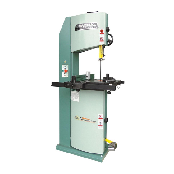
DELUXE 14" WOOD CUTTING BANDSAW
MODEL
# 90-170B M1
VERSION 5_NOVEMBER 12/12 (92207612)
© Copyright General® International 11/2012
Advertisement
Table of Contents

Related Manuals for General 90-170B M1


Summary of Contents for General 90-170B M1
-
Page 1: Specifications
DUST COLLECTION PORT 2 x 4” (102 mm) BASE DIMENSIONS (L x W) 25” x 15” (635 x 381 mm) MOTOR 1 1⁄2 HP , 110V, 1PH, 12.5A WEIGHT VERSION 5_NOVEMBER 12/12 (92207612) 293 LBS (133 kg) © Copyright General® International 11/2012... - Page 2 GENERAL® INTERNATIONAL 8360 Champ-d’Eau, Montreal (Quebec) Canada H1P 1Y3 Telephone (514) 326-1161 • Fax (514) 326-5555 • www.general.ca THANK YOU for choosing this General ® International model 90-170B M1 14” Deluxe Wood Cutting Bandsaw. This bandsaw has been carefully tested and inspected before shipment and if properly used and maintained, will provide you with years of reliable service.
- Page 3 2 years (24 months) from the date of purchase. General® and General® International agree to repair or replace any part or component which upon examination, proves to be defective in either workmanship or material to the original purchaser during this 2-year warranty period, subject to the “conditions...
-
Page 4: Table Of Contents
TABLE OF CONTENTS Rules for safe operation ....Adjusting blade tracking ....17 Electrical requirements . -
Page 5: Rules For Safe Operation
To help ensure safe operation, please take a moment to learn the machine’s applications and limita- tions, as well as potential hazards. General® International disclaims any real or implied warranty and hold itself harmless for any injury that may result from the improper use of it’s equipment. -
Page 6: Electrical Requirements
ELECTRICAL REQUIREMENTS BEFORE CONNECTING THE MACHINE TO THE POWER SOURCE, VERIFY THAT THE VOLTAGE OF YOUR POWER SUPPLY CORRE- SPONDS WITH THE VOLTAGE SPECIFIED ON THE MOTOR I.D. NAMEPLATE. A POWER SOURCE WITH GREATER VOLTAGE THAN NEEDED CAN RESULT IN SERIOUS INJURY TO THE USER AS WELL AS DAMAGE TO THE MACHINE. IF IN DOUBT, CONTACT A QUAL- IFIED ELECTRICIAN BEFORE CONNECTING TO THE POWER SOURCE. -
Page 7: Identification Of Main Parts And Components
IDENTIFICATION OF MAIN PARTS AND COMPONENTS FRONT VIEW BLADE TENSION ADJUSTMENT HANDLE UPPER WHEEL COVER DOOR LOCK KNOB C- BLADE GUARD RIP FENCE RESAW GUIDE BLOCK MITER GAUGE G- TABLE ALIGNMENT PIN FENCE FRONT RAIL LOWER WHEEL COVER DOOR LOCK KNOB FOOT BRAKE MAGNETIC SAFETY SWITCH REAR VIEW... -
Page 8: Unpacking
Carefully unpack and remove the unit and its components from its shipping container and check for missing or damaged items as per the list of contents below. NOTE: Please report any damaged or missing items to your GENERAL® INTERNATIONAL distributor immediately. LIST OF CONTENTS... -
Page 9: Basic Functions Of The Unit
PLACEMENT WITHIN THE SHOP / ESTABLISHING A SAFETY ZONE THIS MODEL 90-170B M1 IS HEAVY. DO NOT OVER-EXERT. THE HELP OF AT LEAST ONE ASSISTANT OR A HOIST WILL BE NEEDED FOR THE FOLLOWING STEP. -
Page 10: Clean Up
CLEAN UP The protective coating on the saw table prevents rust from forming during shipping and storage. Remove it by rub- bing with a rag dipped in kerosene, mineral sprits or paint thinner. (Dispose of potentially flammable solvent-soaked rags according to manufacturer’s safety recommenda- tions.) A putty knife, held flat to avoid scratching the surface, may also be used to scrape off the coating followed by clean-... -
Page 11: Install The Foot Brake
R. 3. Firmly tighten with the supplied 8 mm Allen key. INSTALL THE FENCE ASSEMBLY This model 90-170B M1 is equipped with an Excalibur T- fence and guide rail system. Follow all assembly and adjustment instructions in the 90- 075A manual supplied in the box with the Excalibur Universal Bandsaw Rip Fence System. -
Page 12: Basic Adjustments & Controls
BASIC ADJUSTMENTS AND CONTROLS CONNECTING TO A POWER SOURCE TO REDUCE THE RISK OF SHOCK OR FIRE DO NOT OPER- ATE THE UNIT WITH A DAMAGED POWER CORD OR PLUG. SWITCH OFF REPLACE DAMAGED CORD OR PLUG IMMEDIATELY. TO AVOID UNEXPECTED OR UNINTENTIONAL START-UP , MAKE SURE THAT THE POWER SWITCH IS IN THE OFF POSI- TION BEFORE CONNECTING TO A POWER SOURCE. -
Page 13: Tilting The Table
TILTING THE TABLE The table can be tilted to any angle from 0° to 45° to the right to allow for any type of bevel (or angle) cutting. Refer to the table tilt angle indicator A located under the band- saw table, to set the angle of the table to the desired posi- tion. -
Page 14: Removing/Installing The Blade
REMOVING/INSTALLING THE BLADE Your bandsaw is designed to handle several blade widths ranging from 1/8” and 3/8” used for tight radius curves, up to 1/2” and 3/4” for larger radius curves or for cutting thicker stock. BLADE CLEARANCE Note: When performing blade installation, removal, tensioning or tracking, maximum clearance between the blade and both upper and lower blade guide assemblies is required to minimize friction, which would be damaging to the blade. -
Page 15: Blade Selection
Standard size - 112” (2845 mm) - replacement blades made from high carbon steel can be purchased in a variety of widths from your General® International dealer under the following parts numbers: • #90170-B14:1/4” - 6 TPI, blade thickness: 0.65 mm •... -
Page 16: Adjusting Blade Tension
When working with narrower blades, sawing shorter stock and making tighter curved cuts are best per- formed using less tension This model 90-170B M1 bandsaw is equipped with a blade tension scale, which can be used as a reference for the ideal setting with various blade widths. -
Page 17: Adjusting Blade Tracking
ADJUSTING BLADE TRACKING 3 mm - 1/8" Blade tracking means centering the blade on the wheels A. Ideally, the blade should stay relatively centered on both the upper and lower wheels. Due to natural variations in castings, blade thickness or den- sity and tire wear, absolute perfect centering alignment is rarely attainable. -
Page 18: Adjusting The Upper/Lower Blade Guides Assemblies
ADJUSTING THE UPPER / LOWER BLADE GUIDES ASSEMBLIES 1/32" The guide bearings A keep the blade from moving from side to side during cutting and must be snug but not touching the blade in order to ensure accurate cuts. The space between each guide bearing and the blade must not exceed 0.02"... -
Page 19: Changing Speed Settings
CHANGING SPEED SETTINGS This model 90-170B has 2 different speed settings; low and high. - Low speed is to be used for cutting soft woods over 4" in height or hard woods over 2" in height. - High speed is best for cutting soft woods under 4" in height or hard woods under 2"... -
Page 20: Operating Instructions
Make sure all the blade guards are in place. Make sure the bandsaw table and work area in general are clean and free of sawdust and debris. These steps should always be followed when any adjustment is performed, the blade is changed, or periodically as vibra- tion and normal wear and tear on the machine could throw these parts out of alignment. -
Page 21: Using The Miter Gauge
USING THE MITER GAUGE Using the miter gauge supplied with your bandsaw allows for easier and safer sawing by providing workpiece support when cutting straight (90°) or angled ends (0° to 30°). The miter gauge rides in either the left or right table slot A and can be set to any angle up to 30°... -
Page 22: Periodic Maintenance & Lubrication
PERIODIC MAINTENANCE & LUBRICATION ALWAYS DISCONNECT THE MACHINE FROM THE POWER SOURCE BEFORE PERFORMING ANY LUBRICA- TION OR MAINTENANCE. LUBRICATION Keep the rack and pinion A, blade tension adjustment screw B, as well as the table trunnion C, well greased and free of dust or debris. -
Page 23: Required Maintenance
REQUIRED MAINTENANCE ALWAYS DISCONNECT THE MACHINE FROM THE POWER SOURCE BEFORE PERFORMING ANY MAINTE- NANCE. REPLACING THE BANDSAW BLADE The blade should be replaced when worn out. Refer to the following symptoms to determine whether or not it is time to replace the blade: - It is not cutting as fast. -
Page 24: Replacing The Wheel Tire
REPLACING THE WHEEL TIRE Wheel tires must be replaced if they get worn out or dam- aged. (If it is worn out, the blade will not track straight on the wheels.) Use a flat screwdriver to remove the tire from the groove on the wheel, then install a new tire. -
Page 25: Recommended Optional Accessories
RECOMMENDED OPTIONAL ACCESSORIES We offer a large variety of products to help you increase convenience, productivity, accuracy and safety when using your bandsaw Here’s a small sampling of optional accessories available from your local General International dealer. For more information about our products, please visit our website at www.general.ca... - Page 26 MAIN ASSEMBLY...
-
Page 27: Table Assembly
TABLE ASSEMBLY 108 109 128a 141A 141A-1 141A-2 141A-6 141A-3 141A-4 141A-5... - Page 28 PARTS LIST 90-170B M1 REF # PART. N0. DESCRIPTION SPECIFICATION 90170B-001C SAW FRAME 90170-002 LOCK WASHER 1/2" 90170-003 WASHER 1/2" 90170-004 SQUARE NUT 90170-005 POINTER 90170-006 SPRING 90170-007 HANDLE 90170-008 WASHER 90170-009A UPPER WHEEL BRACKET 90170-010 SCREW 90170-011 UPPER WHEEL SHAFT...
- Page 29 PARTS LIST 90-170B M1 REF # PART. N0. DESCRIPTION SPECIFICATION 90170-046 HEX NUT 3/4" 90170B-047 BEARING HOUSING 90170-048 90170-049 COVER 90170-050 HEX BOLT 3/8"-1 1/2 90170-051 HEX BOLT 3/8"-2 1/2" 90170-052 MOTOR 90170-053 RATCHET LEVER 3/8"-1" 90170-054 90170-055 WASHER 3/8"...
- Page 30 PARTS LIST 90-170B M1 REF # PART. N0. DESCRIPTION SPECIFICATION 90170-114 SET SCREW 1/4" 90170-115 C-RING 90170-116 BALL 90170-117 SPRING 90170-118 SET SCREW 1/4" 90170-119 KNOB 90170-120 GEAR 90170-121 BLADE GUARD 90170-122 THUMB SCREW 1/4"-3/4" 90170-123 HEX BOLT 1/4"-3/4" 90170-124...
-
Page 31: Wiring Diagrams
WIRING DIAGRAM... - Page 32 MODEL 90-170B M1 8360 Champ-d’Eau, Montreal (Quebec) Canada H1P 1Y3 Tel.: (514) 326-1161 Fax: (514) 326-5565 - Fax: (514) 326-5555 - Parts & Service / Order Desk orderdesk@general.ca www.general.ca IMPORTANT When ordering replacement parts, always give the model number, serial number of the machine and...
Need help?
Do you have a question about the 90-170B M1 and is the answer not in the manual?
Questions and answers