Electra Delta 25 Service Manual
Electra delta series; dci series air conditioner, refrigerant/heat pump
Hide thumbs
Also See for Delta 25:
- Service manual (78 pages) ,
- Service manual (75 pages) ,
- Service manual (78 pages)

Subscribe to Our Youtube Channel
Related Manuals for Electra Delta 25


Summary of Contents for Electra Delta 25
-
Page 1: Outdoor Units
Delta DCI Series Indoor Units Outdoor Units Delta 25 DCR 25 Z Delta 35 DCR 35 Z REFRIGERANT REFRIGERANT REFRIGERANT R410A HEAT PUMP NOVEMBER – 2008 SM DELTAZ 1-E.0 GB CONTENTS... - Page 2 LIST OF EFFECTIVE PAGES LIST OF EFFECTIVE PAGES Note: Changes in the pages are indicated by a “Revision#” in the footer of each effected page (when none indicates no changes in the relevant page). All pages in the following list represent effected/ non effected pages divided by chapters.
-
Page 3: Table Of Contents
TABLE OF CONTENTS Table of Contents INTRODUCTION ....................1-1 PRODUCT DATA SHEET ..................2-1 RATING CONDITIONS ..................3-1 OUTLINE DIMENSIONS ..................4-1 PERFORMANCE DATA & PRESSURE CURVES ..........5-1 SOUND LEVEL CHARACTERISTICS ..............6-1 ELECTRICAL DATA ....................7-1 WIRING DIAGRAMS .....................8-1 REFRIGERATION DIAGRAMS ................9-1 10. TUBING CONNECTIONS ..................10-1 11. -
Page 4: Main Features
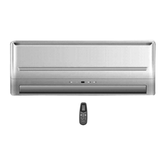
General The new Delta DC Inverter split wall mounted series comprise RC (heat pump) models, as follows: ● Delta 25 ● Delta 35 The indoor Delta units are available as LED display types only, featuring esthetic design, compact dimensions, and low noise operation. -
Page 5: Indoor Unit
INTRODUCTION Indoor Unit The indoor unit is wall mounted, and can be easily fitted to many types of residential and commercials applications. It includes: ● Casing with air inlet and outlet grills. ● A large-diameter tangential fan. ● Bended coil with treated aluminum fins. ●... -
Page 6: Tubing Connections
Inbox Documentation Each unit is supplied with its own installation and operation manuals, one simly remote control manual. Matching Table INDOOR UNITS OUTDOOR UNITS MODEL REFR” Delta 25 Delta 35 √ DCR 25Z R410A √ DCR 35Z R410A SM DELTAZ 1-E.0 GB... -
Page 7: Product Data Sheet
PRODUCT DATA SHEET PRODUCT DATA SHEET Delta 25 / DCR 25Z R410A Model Indoor Unit DELTA 25 DCI Model Outdoor Unit DCR 25 Z R410A Installation Method of Pipe Flared Characteristics Units Cooling Heating Btu/hr 8530(4090-10240) 8530(3410-10910) Capacity 2.5(1.2-3.0) 2.5(1.0-3.2) 0.78... - Page 8 PRODUCT DATA SHEET Delta 35 / DCR 35 Z R410A Model Indoor Unit DELTA 35 DCI Model Outdoor Unit DCR 35 Z R410A Installation Method of Pipe Flared Characteristics Units Cooling Heating Btu/hr 11940(4100-13640) 11940(4100-13330) Capacity 3.5(1.2-4.0) 3.5(1.2-3.9) 1.09 0.97 Power input 3.21 3.61...
-
Page 9: Rating Conditions
RATING CONDITIONS RATING CONDITIONS Rating conditions in accordance with ISO 5151 and ISO 13253 (for ducted units). Cooling: Indoor: C DB 19 C WB Outdoor: 35 C DB Heating: Indoor: C DB Outdoor: 7 C DB 6 C WB Operating Limits 3.1.1 R410A Indoor... - Page 10 OUTLINE DIMENSIONS OUTLINE DIMENSIONS Indoor Unit: Delta 25 DCI Indoor Unit: Delta 35 DCI SM DELTAZ 1-E.0 GB CONTENTS...
-
Page 11: Outline Dimensions
OUTLINE DIMENSIONS Outdoor Unit: DCR 25 Z, DCR 35 Z DCI AIR INTAKE AIR OUTLET SM DELTAZ 1-E.0 GB CONTENTS... -
Page 12: Performance Data & Pressure Curves
PERFORMANCE DATA & PRESSURE CURVES PERFORMANCE DATA Delta 25 / DCR 25 Z R410A 5.1.1 Cooling Capacity (kW) – Run Mode 230[V] : Indoor Fan at High Speed. ID COIL ENTERING AIR DB/WB TEMPERATURE [ OD COIL ENTERING AIR DB... - Page 13 PERFORMANCE DATA & PRESSURE CURVES 5.1.3 Heating Capacity (kW) - Run Mode 230[V] : Indoor Fan at High Speed. ID COIL ENTERING AIR DB TEMPERATURE [ OD COIL ENTERING AIR DB/WB DATA TEMPERATURE [ 1.78 1.66 1.53 -15/-16 0.49 0.54 0.59 1.98 1.86...
- Page 14 PERFORMANCE DATA & PRESSURE CURVES Delta 35 / DCR 35 Z R410A 5.2.1 Cooling Capacity (kW) – Run Mode 230[V] : Indoor Fan at High Speed. ID COIL ENTERING AIR DB/WB TEMPERATURE [ OD COIL ENTERING AIR DB 22/15 24/17 27/19 29/21 32/23...
- Page 15 PERFORMANCE DATA & PRESSURE CURVES 5.2.3 Heating Capacity (kW) - Run Mode 230[V] : Indoor Fan at High Speed. ID COIL ENTERING AIR DB TEMPERATURE [ OD COIL ENTERING AIR DB/WB DATA TEMPERATURE 2.29 2.13 1.97 -15/-16 0.63 0.69 0.76 2.55 2.39 2.23...
- Page 16 PERFORMANCE DATA & PRESSURE CURVES Capacity Correction Factor Due to Tubing Length 5.3.1 Delta 25 DCI : Cooling 1.025 1.00 0.95 0.90 0.85 0.80 0.75 Tubing Length[m ] 5.3.2 Heating 1.025 1.00 0.95 0.90 0.85 0.80 0.75 Tubing Length[m ] SM DELTAZ 1-E.0 GB...
- Page 17 PERFORMANCE DATA & PRESSURE CURVES 5.3.3 Delta 35 DCI : Cooling 1.025 1.00 0.98 0.96 0.94 0.92 0.90 0.88 0.84 0.80 Tubing Length[m ] 5.3.4 Heating 1.01 1.00 0.99 0.98 0.97 0.96 0.95 0.94 0.92 0.90 Tubing Length[m ] SM DELTAZ 1-E.0 GB CONTENTS...
- Page 18 PERFORMANCE DATA & PRESSURE CURVES PRESSURE CURVES 5.4.1 DELTA 25 / DCR 25 Z R410A 5.4.1.1 Cooling => Test Mode Suction Pressure VS.Outdoor Temp. 1200 1100 1000 21/15 DB/WB 24/17 DB/WB 27/19 DB/WB 29/21 DB/WB 32/23 DB/WB Outdoor DB Temperature Discharge Pressure VS.
- Page 19 PERFORMANCE DATA & PRESSURE CURVES 5.4.1.2 Heating => Test Mode Suction Pressure VS. Outdoor Temp. 1000 15 DB 20 DB 25 DB Outdoor WB Temperature Discharge Pressure VS. Outdoor Temp. 3350 3100 2850 2600 2350 15 DB 2100 20 DB 25 DB 1850 1600...
- Page 20 PERFORMANCE DATA & PRESSURE CURVES 5.4.2 DELTA 35 / DCR 35 Z R410A 5.4.2.1 Cooling => Test Mode Suction Pressure VS. Outdoor Temp. 1200 1100 1000 21/15 DB/WB 24/17 DB/WB 27/19 DB/WB 29/21 DB/WB 32/23 DB/WB Outdoor DB Temperature Discharge Pressur e VS. Outdoor Temp. 4000 3750 3500...
- Page 21 PERFORMANCE DATA & PRESSURE CURVES 5.4.2.2 Heating =>Test Mode Suction Pressure VS. Outdoor Temp. 1000 15 DB 20 DB 25 DB Outdoor WB Temperature Discharge Pressure VS. Outdoor Temp. 4000 3750 3500 3250 3000 2750 2500 15 DB 2250 20 DB 2000 25 DB 1750...
-
Page 22: Sound Level Characteristics
SOUND LEVEL CHARACTERISTICS Sound Pressure Level Figure 1. Wall Mounted Figure 2. Floor Mounted Figure 3. Ducted Figure 4. Cassette Sound Pressure Level Spectrum (Measured as Figure 1) Delta 25 Delta 35 FAN SPEED LINE SM DELTAZ 1-E.0 GB CONTENTS... - Page 23 SOUND LEVEL CHARACTERISTICS Outdoor units Microphone Distance from Unit Sound Pressure Level Spectrum (Measured as Figure 5) DCR 25 Z Cooling DCR 25 Z Heating DCR 35 Z Cooling DCR 35 Z Heating SM DELTAZ 1-E.0 GB CONTENTS...
-
Page 24: Electrical Data
ELECTRICAL DATA ELECTRICAL DATA Single Phase Units MODEL Delta 25 Delta 35 To indoor To indoor Power Supply 1PH,220-240V,50Hz 1PH,220-240V,50Hz Max Current, A Circuit Breaker,A Power Supply Wiring No. X 3x1.0 mm 3x1.5 mm Cross Section, mm nterconnecting Cable RC 4x1.0 mm... -
Page 25: Wiring Diagrams
WIRING DIAGRAMS WIRING DIAGRAMS Delta 25 / DCR 25 Z, Delta 35 / DCR 35 Z SM DELTAZ 1-E.0 GB CONTENTS... -
Page 26: Refrigeration Diagrams
REFRIGERATION DIAGRAMS REFRIGERATION DIAGRAMS Heat Pump Models 9.1.1 Delta 25 / DCR 25 Z DCI SM DELTAZ 1-E.0 GB CONTENTS... - Page 27 REFRIGERATION DIAGRAMS 9.1.2 Delta 35 / DCR 35 Z DCI SM DELTAZ 1-E.0 GB CONTENTS...
-
Page 28: Tubing Connections
TUBING CONNECTIONS TUBING CONNECTIONS TUBE (Inch) ¼” ⅜” ½” ⅝” ¾” TORQUE (Nm) Flare Nuts 11-13 40-45 60-65 70-75 80-85 Valve Cap 13-20 13-20 18-25 18-25 40-50 Service Port Cap 11-13 11-13 11-13 11-13 11-13 Valve Protection Cap-end Refrigerant Valve Port (use Allen wrench to open/close) Valve Protection Cap Refrigerant Valve Service Port Cap... -
Page 29: Control System
CONTROL SYSTEM CONTROL SYSTEM 11.1 Electronic Control 11.1.1 General Functions and Operating Rules The DCI software is fully parametric.All the model dependent parameters are shown in Blue color and with Italic style [parameter]. The parameters values are given in the last section of this control logic chapter of the service manual. - Page 30 CONTROL SYSTEM 11.1.3.3 Frequency Changes Control Frequency change rate is 1 Hz/sec. 11.1.3.4 Compressor Starting Control Frequency Step 3 Step 2 Step 1 Minute Time Minute Min 10 Minutes 11.1.3.5 Minimum On and Off Time 3 minutes. 11.1.4 Indoor Fan Control 10 Indoor fan speeds are determined for each model.
- Page 31 CONTROL SYSTEM Speed Controlled by High Relay Triac (40% to 95% effective voltage) 11.1.6.2 OFAN Operation in Cooling Mode With keeping the OFAN general rules above in the highest priority, the operation of the OFAN will be operating as the following: Time After Compressor start up (minutes) Initial 0 –...
-
Page 32: Fan Mode
CONTROL SYSTEM 11.1.8 Reversing Valve (RV) Control Reversing valve is on in heat mode. Switching of RV state is done only after compressor is off for over 3 minutes. 11.2 Fan Mode In high/ medium/ low indoor fan user setting, unit will operate fan in selected speed. In AutoFan user setting, fan speed will be adjusted automatically according to the difference between actual room temperature and user set point temperature. -
Page 33: Dry Mode
CONTROL SYSTEM 11.6 Dry Mode As long as room temperature is higher then the set point, indoor fan will work in low speed and compressor will work between 0 and MaxNLOADIF1C Hz. When the room temperature is lower than the set point, compressor will be switched OFF and indoor fan will cycle 3 minutes OFF, 1 minute ON. - Page 34 CONTROL SYSTEM 11.7.3 Compressor over Heating Protection Compressor temperature can be in one of 5 control zones (4 in protection, and 1 normal), according to the following chart. Stop-Compresor CTTOH4 CTTOH3 CTTOH2 CTTOH1 Normal Compressor Temperature Control Status Else Increases Norm Stop Compressor 11.7.4...
- Page 35 CONTROL SYSTEM 11.7.5 Heat Sink Over Heating Protection A new control status will be set according to the following graph every one-minute or whenever when going up by the rows. is the current reading of HST and HST is the last reading of HST. -HST <-1 >1...
- Page 36 CONTROL SYSTEM 11.7.6.2 Deicing Protection Procedure Threshold COMP max. 12 minutes HEAT COOL OFAN EEVDeicerOpen T1 = DEICT1, T2 = DEICT2, T3 = DEICT3 11.7.7 Condensate Water Over Flow Protection Each of the pins P1, P2, P3 can have two options: 1 –...
- Page 37 CONTROL SYSTEM Water Level LEVEL4 LEVEL2&3 LEVEL1 Pump NLOAD BLINK OPER LED NORMAL 11.7.7.2 1 Level Logic (used in all models except for floor/ceiling models) Level Don’t care Normal Don’t care Overflow Overflow when Overflow when unit is ON unit is OFF Overflow Water Level Normal...
- Page 38 CONTROL SYSTEM 11.8 Indoor Unit Dry Contact Indoor unit Dry contact has two alternative functions that are selected by J8. Function Contact = Open Contact = Short J8 = Open Presence Detector Connection No Limit Forced to STBY J8 = Short Power Shedding Function No Limit Limit NLOAD...
- Page 39 CONTROL SYSTEM 1. Lights up when the Air Conditioner is connected to power and the mode is STBY. STAND BY 2. Blinks for 3 seconds, when the system is switched to Heat Mode INDICATOR by using the Mode/Reset Switch on the unit (the operation indicator will be off during this blinking time).
-
Page 40: Jumper Settings
CONTROL SYSTEM 11.10.2 Outdoor Unit Controller Indicators Unit has three LED’s. SB LED, STATUS LED, FAULT LED. SB LED is ON when power is ON (230 VAC), STATUS LED is ON when COMP is ON, and Blinks according to diagnostics mode definitions when either fault or protection occurs. - Page 41 CONTROL SYSTEM 11.11.2 Outdoor Unit Controller 11.11.2.1 Hardware Jumpers JP9 JUMPER LAYOUT EEPROM Data (PIN 9) ODU3 (PIN 7) ODU2 (PIN 5) ODU1 (PIN 3) ODU0 (PIN 1) (PIN 10) GND (PIN 8) (PIN 6) (PIN 4) (PIN 2) ODU MODEL SELECTION ODU3 ODU2 ODU1...
- Page 42 CONTROL SYSTEM 11.12 Test Mode 11.12.1 Entering Test Mode System can enter Test mode in two ways: Automatically when the following conditions exists for 30 minutes continuously: o Mode = Cool, Set point = 16, Room temperature = 27±1, Outdoor temperature = 35±1 o Mode = Heat, Set point = 30, Room temperature = 20±1, Outdoor temperature = 7±1...
- Page 43 CONTROL SYSTEM 11.13.1.2 Model Depended Parameters: Models Parameter name NLOAD limits as a function of selected indoor fan speed MaxNLOADIF1C MaxNLOADIF2C MaxNLOADIF3C MaxNLOADIF4C MaxNLOADIF5C Indoor Fan speeds IFVLOWC IFLOWC IFMEDC 1050 1000 IFHIGHC 1200 1200 IFTURBOC 1300 1300 IFVLOWH IFLOWH IFMEDH 1050 1100...
-
Page 44: Troubleshooting
TROUBLESHOOTING TROUBLESHOOTING 12.1 ELECTRICAL & CONTROL TROUBLESHOOTING WARNING!!! When Power Up – the whole outdoor unit controller, including the wiring, is under HIGH VOLTAGE!!! Never open the Outdoor unit before turning off the Power!!! When turned off, the system is still charged (400V)!!! It takes about 4 Min. - Page 45 TROUBLESHOOTING SYMPTOM PROBABLE CAUSE CORRECTIVE ACTION Compressor is over heated and unit does not generate EEV problem Check EEV capacity Units goes into protections Control problem or Perform diagnostics (See 13.1.3 below), and and compressor is stopped refrigeration system follow the actions described. with no clear reason problem Compressor motor is...
- Page 46 TROUBLESHOOTING 12.1.3.1 Indoor unit Diagnostics Problem RT-1 is disconnected RT-1 is shorted RT-2 is disconnected RT-2 is shorted Reserved Communication mismatch No Communication No Encoder Reserved Outdoor Unit Fault … Reserved Defrost protection Deicing Protection Outdoor Unit Protection Indoor Coil HP Protection Reserved Reserved EEPROM Not Updated...
- Page 47 TROUBLESHOOTING 13.1.3.3 Outdoor unit Diagnostics DCR 22 / 25 / 35 diagnostics Problem OCT shorted/disconnected CTT shorted/disconnected HST shorted/disconnected OAT shorted/disconnected OMT shorted/disconnected … Reserved IPM Fault Reserved DC under voltage Reserved Zero Crossing detection fault Mismatch between IDU & ODU models No Communication …...
- Page 48 TROUBLESHOOTING Use MegaTool according to following procedure: Setup MegaTool software: copy the software to the computer. Connect RS232C port in computer with MegaTool port in Indoor/Outdoor unit controller by the connection wire. Run the software and choose the COM port, you can monitor the A/C system state in monitor tab.
-
Page 49: Exploded Views And Spare Parts Lists
EXPLODED VIEWS AND SPARE PARTS LISTS EXPLODED VIEWS AND SPARE PARTS LISTS 13.1 Indoor Unit: Delta 25, Delta 35 DCI SM DELTAZ 1-E.0 GB 13-1 CONTENTS... -
Page 50: Indoor Unit: Delta 25 Dci
EXPLODED VIEWS AND SPARE PARTS LISTS 13.2 Indoor Unit: Delta 25 DCI Part No. Description Quan. 453037000 Grill A / DELTA 22,25 453100500 Grill L axis 453100600 Grill R axis 453036500 Filter for DELTA 7/9 465720000 Silk-screen front frame for Electra... -
Page 51: Indoor Unit: Delta 35 Dci
Grill A / DELTA 12 453100500 Grill L axis 453100600 Grill R axis 453082900 Filter for DELTA 12 465720001 Silk-screen front frame for Electra 4525987 SCREW COVER 453058201 Evap. System Assy./DELTA 35 4523526 BERAING ASSY FAN 4527111 FAN ASSY PLASTIC 452784401 IOD-12 Air Outlet Assy. -
Page 52: R410A
EXPLODED VIEWS AND SPARE PARTS LISTS 13.4 Outdoor Unit: DСR 25 Z, DCR 35 Z R410A DCI 13-4 SM DELTAZ 1-E.0 GB CONTENTS... - Page 53 EXPLODED VIEWS AND SPARE PARTS LISTS 13.5 Outdoor Unit: DСR 25 Z DCI Part No. Description Quan. 4522551 Grille A of GCN 4523441 Front panel A Painting assy 4519251 Axial Fan OD=400 467400040 Sensor/OAT & OMT 467400200 Compressor top thermistor(CTT) 467400023 Outdoor coil thermistor(OCT) 460000032R...
- Page 54 EXPLODED VIEWS AND SPARE PARTS LISTS 13.6 Outdoor Unit: DСR 35 Z DCI Part No. Description Quan. 4522551 Grille A of GCN 4523441 Front panel A Painting assy 4519251 Axial Fan OD=400 467400040 Sensor/OAT & OMT 467400200 Compressor top thermistor(CTT) 467400023 Outdoor coil thermistor(OCT) 460000033R...
-
Page 55: Appendix A
APPENDIX A APPENDIX A INSTALLATION AND OPERATION MANUAL ► OPERATING MANUAL DELTA 25, 35 DCI / DCR 25Z, 35Z ► INSTALLATION MANUAL DELTA 25, 35 DCI / DCR 25Z, 35Z 14-1 SM DELTAZ 1-E.0 GB CONTENTS...
Need help?
Do you have a question about the Delta 25 and is the answer not in the manual?
Questions and answers