Shure SLX2 Service Manual
Shure slx2 wireless handheld transmitter service manual
Hide thumbs
Also See for SLX2:
- Quick setup manual (69 pages) ,
- User manual (60 pages) ,
- User manual (27 pages)
Table of Contents
Advertisement
SLX2 WIRELESS HANDHELD TRANSMITTER
PRODUCT DESCRIPTION
FEATURES
2006, Shure Incorporated
©
25A1090 (Rev.3)
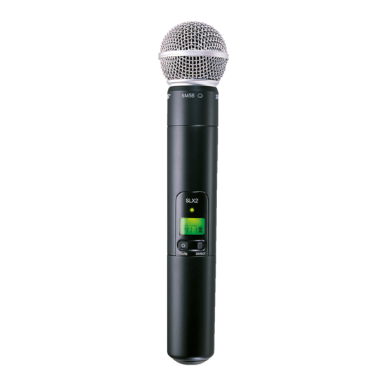
The Shure Model SLX2 is a µP (microprocessor) controlled frequency agile UHF
handheld transmitter operating over the frequency range of 518 to 865 MHz (in eight
different 24 MHz-wide frequency bands). The transmitter will operate for a minimum of 8
hours using two "AA" alkaline batteries. The User Interface includes "mode" and "set"
buttons, and an LCD that displays battery status, group/channel, and transmitter/
receiver frequency synchronization. The SLX2 has a plastic enclosure, and utilizes an
internal antenna for optimum range and reliability. This product is intended for use in
entry-level presentation, installed, and performance markets.
1.
Frequency agile; microprocessor controlled. Model number extension determines frequency band
of operation.
2.
Minimum of 12 compatible systems per SKU in the U.S. Additionally, a minimum of 12 compatible
systems in the top 50 U.S. markets across all three domestic SKU's (H5, J3, and L4).
3.
Operating frequency programmable locally or from the receiver using a built-in IR link.
4.
Designed for use with "AA" alkaline batteries (2 required). May also be used with rechargeable "AA"
batteries. Note: battery condition indicator is calibrated for alkaline batteries and may not be accu-
rate with rechargeable types. Electrical reverse battery protection is included.
5.
Minimum battery life of 8 hours with new "AA" alkaline batteries.
6.
Designed for use with SM58, BETA 58, SM86, and BETA 87A&C microphone heads. Compatible
with "active load" or standard heads (active load circuitry to be incorporated in heads).
7.
Tone key squelch.
8.
Power/Mute and Select buttons with LCD display for frequency group/channel selection and con-
trol. LED backlight for easy reading of LCD display.
9.
Bicolor, green/red LED for power "on" and low battery, mute and infrared link indications.
10. Rugged plastic construction.
11.
Utilizes Shure Patented ARC (Audio Reference Companding) audio processing.
SLX2 Wireless Transmitter Service Manual
SLX
mute
select
25A1090
Advertisement
Table of Contents
Troubleshooting

Subscribe to Our Youtube Channel
Related Manuals for Shure SLX2


Summary of Contents for Shure SLX2
- Page 1 SLX2 WIRELESS HANDHELD TRANSMITTER PRODUCT DESCRIPTION The Shure Model SLX2 is a µP (microprocessor) controlled frequency agile UHF handheld transmitter operating over the frequency range of 518 to 865 MHz (in eight different 24 MHz-wide frequency bands). The transmitter will operate for a minimum of 8 hours using two "AA"...
- Page 2 Two gain settings are available on the SLX2. Choose a setting appropriate for vocal volume and for the performing environment. Use the tip of a pen or a small screwdriver to move the switch.
- Page 3 Note: the transmitter cannot be used to change master list settings. INCOMPATIBLE Frequency Warning Incompatible MASTER LIST i8 i8 GROUP CHANNEL The INCOMPATIBLE warning indicates that the receiver and transmitter are transmitting on different frequency bands. Contact your Shure retailer for assistance. 25A1090 (Rev.3)
- Page 4 SW100). Capacitor C140 couples the signal into a pre-emphasis network formed by R140, R141, and C141. Next, the audio signal enters the patented Shure ARC™ processor. The main elements in this section are the VCA (IC100-5) and the RMS Detector (IC100-4). The VCA, or Voltage Controlled Amplifier, is a DC controlled amplifier.
- Page 5 RF CIRCUIT DESCRIPTION RF SECTION The system block diagram is shown above. The SLX2 uses a PLL system with direct carrier frequency modulation. Processed audio enters the VCO through a passive "reflection" network before being applied to the varactor diode (D500) through choke L503. The VCO is shielded to prevent external RF fields from affecting its operation, and to help control radiated emissions of its harmonics.
- Page 6 with C600 - C604. The collector of Q600 feeds the power amplifier stage via an impedance matching network consisting of L602, C611, and C618. The bias voltage for the RF power amplifier (Q601) is supplied by R601 and R604. Its operat- ing current is controlled via emitter resistor R606.
- Page 7 In ATE Mode, each band has a three test frequencies that are controlled by the logic levels at test points TP_PA0 and TP_PA1. Frequency TP_PA0 TP_PA1 Center High Test Frequencies (MHz) SLX2 518.400 572.400 806.125 638.400 702.100 740.125 800.525 838.100 Center 529.500...
- Page 8 This table shows the variant resistor values and resulting voltages at TP_RFBAND for each band. RF BAND TP_RFBAND(+/- 0.10V) 1.00k 0.30V 2.99k 0.76V 4.99k 1.10V 7.50k 1.41V 12.10k 1.81V 18.2k 2.13V 30.1k 2.48V 49.9k 2.75V Note: Voltages are calculated with a 3.30V (+/- 0.10V) reference from the power supplies.
- Page 9 NOTES 25A1090 (Rev.3)
- Page 10 Frequency Counter HP 53181/HP 5385A Power Supply Power Supply must be able to supply 3Vdc with an internal ammeter. Shielded test lead Shure PT1838F BNC (Male) to BNC (Male) cable (1) Shure PT1838A UA820 Antenna Frequency Dependent Audio Test Head...
- Page 11 FREQUENCY=(Look at tables on pages 18 thru 23) Extend the UA820 away from the analyzer into the horizontal plane (straight out). Align the SLX2 antenna parallel to the UA820 as close as possible. Move the unit along the UA820 antenna until you find a maximum peak.
- Page 12 ASSEMBLY AND DISASSEMBLY !CAUTION! Observe precautions when handling this static-sensitive device. EXPLODED VIEW I.D. # Description Part Number 0001 Cartridge 0002 Tuned PCB assembly 200--082 0003 PCB assembly, IR 190A098-01 0004 PCB, head board 190-057-03-34 0005 Contact 53F2039A 0006 Frame, internal 65B8467 0007 Retaining ring...
- Page 13 Frequency Counter HP 53181/HP 5385A Receiver Matching SLX4 Receiver 50 ohm, RG-174 BNC to open (stripped) Shure PT 1824 coaxial cable or "rocket launcher" tip (P/N 95A8278). For JB, Murata cable # MXGS83RK3000 may be used. Audio Test Head Shure PT1840...
- Page 14 Solder the center of a 50Ω unshielded test cable (PT1824) to the node between L606 and L641, and the shield to ground. Connect the audio generator output to the Mic Test Head input of the transmitter as required. Turn on the SLX2 by pressing and holding the POWER button, SW325 Frequency Level GRP. 1 / GRP.
- Page 15 FREQUENCY ALIGNMENT Set the transmitter to MID frequency (see table on page 14). Connect the 50 Ω cable to a frequency counter. Adjust variable capacitor CV501 until the frequency counter measurement matches the appropriate frequency on the table below, ± 1 kHz. . GROUP CODE FREQUENCY RANGE 529.500 Mhz ±...
- Page 16 Connect the audio analyzer output to the Mic Test Head input of the transmitter. Power ON the receiver. Apply +3V to the battery terminals on the SLX2 and power up the unit. Set the audio analyzer frequency to 1kHz. Adjust the audio analyzer amplitude level (typically = -6.5 dBu) to obtain -13 dBu ± 0.1dB at TPA1.
- Page 17 NOTES: 25A1090 (Rev.3)
- Page 18 FREQUENCY TABLES H5: 518.000 - 542.000 MHz Preprogrammed frequencies in total: > 120 Group 1 Group 2 Group 3 Group 4 Group 5 Group 6 518.400 519.250 518.200 519.775 519.100 518.425 521.500 520.500 519.675 522.500 521.225 520.400 523.575 522.225 520.800 524.200 522.550 523.425...
- Page 19 JB: 806.000 - 810.000 MHZ Preprogrammed frequencies in total: 21 Group 1 Group 2 Group 3 Group 4 Group 5 Group 6 806.250 806.375 806.125 806.500 806.125 806.250 807.500 808.625 807.375 807.375 807.375 807.250 809.625 809.750 809.500 808.625 808.375 808.500 809.625 809.750 809.375...
- Page 20 P4: 702.000 - 726.000 MHZ Preprogrammed frequencies in total: Group 1 Group 2 Group 3 Group 4 Group 5 Group 6 Group 7 Group 8 Group 9 702.200 703.750 703.650 702.750 703.750 702.100 704.775 702.300 703.000 704.200 705.975 705.650 704.500 705.750 704.025 706.225...
- Page 21 Q4: 740.000 - 752.000 MHZ Preprogrammed frequencies in total: Group 1 Group 2 Group 3 Group 4 740.125 740.125 740.125 740.125 741.500 741.950 741.225 740.800 743.375 743.500 742.925 741.825 744.600 745.675 744.325 743.075 746.325 747.400 745.425 745.125 748.500 748.625 746.875 746.575 750.050 750.500...
- Page 22 R5: 800.000 - 820.000 MHZ Preprogrammed frequencies in total: Group 1 Group 2 Group 3 Group 4 Group 5 Group 6 Group 7 801.250 801.225 800.950 800.525 801.475 800.600 800.650 804.825 804.800 802.950 801.925 803.025 802.050 803.125 806.975 806.950 804.325 803.650 805.800 804.275...
- Page 23 S6: 838.000–865.000 MHZ Preprogrammed frequencies in total: Group 1 Group 2 Group 3 Group 4 Group 5 Group 6 Group 7 Group 8 838.200 838.150 838.550 854.200 855.475 855.075 854.750 854.750 841.450 839.375 839.775 855.300 857.425 857.775 855.850 855.850 843.275 841.300 841.700 856.700...
- Page 24 AGENCY APPROVALS Note: Consult Global Compliance for latest applicable standards (H5, J3, L4) - Part 74 (H5, J3, L4) - RSS-123 (H5, J3, L4, P4, Q4, R5, S6,) - EN 300 422 and EN 301 489 TELEC (JB) - RCR STD-22 PRODUCT PERFORMANCE CHARACTERISTICS SPECIFICATION Value...
- Page 25 NOTES 25A1090 (Rev.3)
- Page 26 PRODUCT SPECIFICATIONS MECHANICAL Overall Dimensions 64 mm x 109 mm x 19 mm (2.50 x 4.30 x 0.75 in.) Weight 73 grams (2.6 oz), without batteries Housing Molded ABS case and battery cover GENERAL Frequency Range and Transmitter Output Level Band Range Transmitter output...
- Page 27 RF Transmitter Output 30 mW maximum (dependent on applicable country regulations) Dimensions 254 mm H x 51 mm dia. (10x2 in) including SM58 cartridge Weight 375.6 grams (13.25 oz) without batteries Housing Molded ABS handle and battery cup Power Requirements 2 “AA”...
-
Page 28: Troubleshooting
TROUBLESHOOTING Servicing will be more efficient when the history of the unit is known and can be taken into ac- count. The service strategy should be different when a unit fails on the production line than when it fails in the field, because if it fails on the line there is a possibility of incorrect or missing parts. If the unit has failed in the field, check for signs of tampering or hand soldering that could indicate that the customer has modified the unit or has attempted to repair it. - Page 29 DEVIATION PROBLEMS If TR200 can't be adjusted to obtain proper deviation, try to isolate the problem to the Audio or RF section. To check the RF section, set the transmitter frequency to the frequency listed in Table 1.2 in Section IV and verify that the tuning voltage of the VCO is correct. To check the audio section, apply -10dBu at 1kHz to TPA0.
- Page 30 (1) = PLL_LE @ pin 34, (2) = PLL_DATA @ pin 35, (3) = PLL_CLOCK @ pin 36 T = 1.800s: Microcontroller pin 6 (RF_GND_ON) goes from 0V to 5V. RF carrier gets unmuted. T = 2.000s: Tone-key is turned on. You will see a square wave (Vpp = 5V, f0=32768Hz) at microcontroller pin 18 (TONEKEY_SQUARE).If these stages can be captured with the scope, the microcontroller did its part to let audio go through the system.
-
Page 31: Replacement Parts
740-752 MHz KOREA 200Q410304 800-820 MHz EUROPE 200R510304 838-865 MHz GREAT BRITAIN 200S610304 806-810 MHz JAPAN 200JB10304 SLX2 HARDWARE REPLACEMENT PARTS Reference Description Shure Designation Part Number IR Assembly 190A10302 IR Detector 40kHz 188A617 3 Pin Male Connector Strip 170A76... - Page 32 LCD Bezel 53A8573B MP15 95A8991 MP16 LCD Zebra Connector 80A8257 MP17 Compression Pad (For Positive Battery Contact) 38D189 SLX2 REPLACEMENT PARTS (TOP) Reference Description Shure Designation Part Number C100 Capacitor, Tantalum, SMD1206, 15uF, 10V, 10% 151AC156KA C162 Capacitor, Tantalum, SMD1411, 10uF, 16V, 10%...
- Page 33 Switch, Slide, 2-Position 155A32 TR160, 200 Trim-pot., Line, 100KΩ 146E10 TR640 Trim-pot., Line, 470Ω 146A10 Y500 Crystal, Quartz, SMD, 16MHz 140A26 MICROCONTROLLER (IC300) SELECTION Country Shure Part Number Code 188A585A 188B585A 188C585A 188D598A 188E585B 188F585A 188G585A 188H585B FREQUENCY DEPENDENT PARTS** Frequency Code...
- Page 34 E603 600Ω 600Ω 600Ω 600Ω L301 220nH 220nH 220nH 180nH 180nH 180nH 180nH L302 220nH 220nH 220nH 180nH 180nH 180nH 180nH L303 220nH 220nH 220nH 180nH 180nH 180nH 180nH L400 470nH 470nH 470nH 470nH 220nH 220nH 220nH 220nH L401 470nH 470nH 470nH 470nH...
- Page 35 SLX2 PRINTED CIRCUIT BOARD ASSEMBLY - SLX2 TOP VIEW BOTTOM VIEW 25A1090 (Rev.3)
Need help?
Do you have a question about the SLX2 and is the answer not in the manual?
Questions and answers
SLX2 BEAT58A 新品電池を入れて電源を押しても 電源が入りません。送信機は2本ありますが二本とも電源が入りません故障でしょうか?