Table of Contents
Advertisement
Quick Links
I
i n d ex
INSTRUCTION MANUAL
BEDIENUNGSANLEITUNG
MANUEL D'INSTRUCTIONS
COLOUR CCD camera
CCD-Farbkamera
Caméra CCD COULEUR
CCD
About this manual
•
Before installing and using the camera, please read this manual
carefully. Be sure to keep it handy for later reference.
•
This manual gives basic connections and operating instructions for 2
PAL models (VCC-4594P, 4592P).
Über diese Bedienungsanleitung
•
Lesen Sie bitte vor der Montage und dem Inbetriebnehmen der
Kamera zuerst diese Bedienungsanleitung sorgfältig durch und
bewahren Sie sie zum späteren Nachschlagen auf.
•
In dieser Anleitung finden Sie die Anschlüsse und die
Grundbedienung für 2 PAL-Modelle (VCC-4594P und 4592P)
A propos de ce manuel
•
Avant d'installer et d'utiliser la caméra, veuillez lire ce manuel
attentivement. Gardez-le à portée de main pour toute référence
ultérieure.
•
Ce manuel couvre les branchements et instructions pour
l'utilisation de base pour 2 modèles de format PAL
(VCC-4594P et 4592P).
2 PAL
VCC-4594P
VCC-4592P
VCC-4594P, 4592P
Advertisement
Table of Contents

Related Manuals for Sanyo VCC-4594P


Summary of Contents for Sanyo VCC-4594P
- Page 1 Lesen Sie bitte vor der Montage und dem Inbetriebnehmen der Kamera zuerst diese Bedienungsanleitung sorgfältig durch und bewahren Sie sie zum späteren Nachschlagen auf. 2 PAL VCC-4594P, 4592P • In dieser Anleitung finden Sie die Anschlüsse und die Grundbedienung für 2 PAL-Modelle (VCC-4594P und 4592P)
-
Page 2: Table Of Contents
CONNECTIONS ..................9 • Horizontal resolution, more than 520 TV lines SETTINGS....................1 1 • Power supply: 24 V AC operation (VCC-4594P) TROUBLESHOOTING................1 7 12 V DC operation (VCC-4592P) SPECIFICATIONS..................1 8 ACCESSORIES Lens iris plug (4-pin) ..............1 pc. -
Page 3: Precautions
Disconnect the power greasy smoke or steam, where the dampness may get too high, or cord immediately, and consult your dealer (or a Sanyo Authorized where there is a lot of dust. -
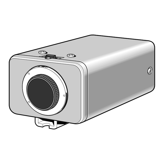
Page 4: Parts Names
G C B Power input terminal • VCC-4594P: 24 V AC input terminal (24 V AC, GND) • VCC-4592P: 12 V DC input terminal (12 V DC, NC, +, –) Camera setup section (under the cover) If due to installation conditions or environment the settings may need to be modified for best results (see "SETTINGS"). - Page 5 PARTS NAMES Flange-back lock screw Lens mount cap The cap is installed to protect the lens mount section. Remove the lens mount cap before installing a lens (sold separately). Flange-back adjustment lever (See page 6) Camera installation bracket The bracket can be fixed at the top or bottom of the camera. When fixing the bracket, be sure to use the longer screws and install the shorter screws on the opposite side to seal the openings.
-
Page 6: Concerning Auto-Iris Lenses
ALC and LEVEL volume level controls are available on the lens for iris adjustments. (Set the A.I. LENS switch to the VIDEO position.) Compatible auto-iris lenses 1/3 inch Sanyo DC type lens VIDEO type lens VCL-CS8LY: Standard angle, f= 8 mm... -
Page 7: Flange-Back Adjustment
FLANGE-BACK ADJUSTMENT If the pick-up surface is not correctly positioned with relation to the lens focal point, the picture will be out of focus (in particular when using auto-iris power zoom lenses, sold separately). If that is the case, adjust the flange-back position as described below. -
Page 8: Mounting The Lens
MOUNTING THE LENS Please use a DC type auto-iris lens (sold separately). Checking the lens mount Do not use a lens if length “L” is more than 5 mm. If not, that may damage the camera and prevent proper installation. Remove the lens mount cap from the camera. - Page 9 MOUNTING THE LENS Rewiring the lens cable in the lens iris plug Prepare the lens cable. Cut the cable at the plug, then remove approx. 8 mm of the cable sheath and strip about 2 mm from each wire. Install the lens iris plug. Solder the cable to the pins following the correct pin layout (refer to the table and illustrations), then close the plug cover.
-
Page 10: Connections
(Video signal connections) : VIDEO IN : VIDEO OUT (VCC-4594P only) When using this unit, the supplied clamping core (A or B) must be installed on the power cord and BNC cable, in order to prevent Basic connection for monitoring or recording electromagnetic interference to the other devices connected. - Page 11 CONNECTIONS – DC 12 V – (Video signal connections) : VIDEO IN : VIDEO OUT (VCC-4592P only) The POWER indicator (A) will light. Adjust the picture on the monitor using the Brightness and Contrast controls. Basic connection for monitoring or recording Coaxial cable type and maximum length The peripheral devices (VCR, monitor, lens, etc.) and cables are •...
-
Page 12: Settings
A. I. LENS SC/SYNC White balance switch (WB) and colour (R or B) adjustment volume External sync setting (SYNC: LL/INT) (VCC-4594P only) External sync setting (SC-P1) adjustable (VCC-4592P only) External sync horizontal adjustment (H-P) adjustable Auto-iris lens setting (A.I. LENS), see page 5... - Page 13 SETTINGS High speed electronic shutter setting Iris function setting Normally, the speed setting switches for the high speed electronic This should normally be set to the down (AI) position. shutter are all set to the down (OFF) position. This sets the electronic Use a manual or fixed iris lens and set the lens aperture shutter speed to 1/50 sec.
-
Page 14: Backlight Compensation Setting
SETTINGS (MULT mode: 64 sections) Backlight compensation setting This camera has two different backlight compensation functions: Normally backlight compensation switch 6 (MULT) and 7 (CENT) are set to the down (OFF) position. Change the backlight compensation switch settings depending on the conditions. •... -
Page 15: White Balance Adjustment
SETTINGS White balance adjustment Line phase adjustment (VCC- 4594P only) Normally the switch 8 (WB) is set to the down (ATW: auto white When using a camera switcher to connect 2 cameras or more to one balance) position and the white balance is adjusted automatically. If a monitor, there may be a vertical roll of the images when switched. - Page 16 SETTINGS External sync adjustment (VBS) (VCC-4592P only) Lens iris adjustment If using a DC type auto-iris lens, you will need to set the LEVEL Connect the VBS signal output for the other camera to the VBS (VR301) volume when shooting in the conditions described below. IN connector at the rear of this camera.
- Page 17 SETTINGS C • B/W (colour/black and white) switch setting Manual colour/black and white setting This switch lets you select the timing of the automatic switching of Connect each pin of the CONTROL terminal as indicated below, to the optical filter to colour image or black and white image, according set the image to black and white or colour as desired.
-
Page 18: Troubleshooting
This camera is a precision instruments and if treated with care, will provide years of satisfactory performance. However, in the event of a problem, the owner is advised not to attempt to make repairs or open the cabinet. Servicing should always be referred to your dealer or Sanyo Authorized Service Centre. -
Page 19: Specifications
Humidity: less than 90% (no condensation) Interlace PLL 2:1 interlace Power supply Image device 24 V AC, 50 Hz (VCC-4594P) 1/3 inch solid state image device CCD 12 V DC (VCC-4592P) Picture elements 795 (H) x 596 (V) Power consumption...
Need help?
Do you have a question about the VCC-4594P and is the answer not in the manual?
Questions and answers