
Summary of Contents for basic coatings Dirt Dragon
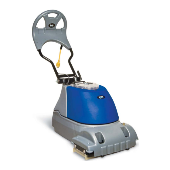
- Page 1 Dirt Dragon WOOD FLOOR CLEANING MACHINE Operator and Parts Manual 1001 Brown Avenue • Toledo, Ohio 43607-0127 • Customer Service: 800-441-1934 Fax: 800-942-2007 • Technical Service: 877-856-5954 • www.basicoatings.com...
-
Page 2: Table Of Contents
TABLE OF CONTENTS Receiving the Machine ........... 3 Introduction ..............3 Technical Specifications ..........4 General Safety Regulations ........... 5 Machine Preparation ............. 6 Operation ..............7 - 8 Turning Off the Machine ..........9 Daily Maintenance ..........10 - 11 Troubleshooting ............ -
Page 3: Receiving The Machine
RECEIVING THE MACHINE Immediately check, when receiving the machine, that all the materials indicated on delivery documents have been received and also that the machine has not been damaged in transit. If it has been damaged, this damage must be immediately re- ported to the shipper and also to our customer service department. -
Page 4: Technical Specifications
TECHNICAL DESCRIPTION Measurement Unit Dirt Dragon ™ Cleaning Width Inches Brush Diameter Inches Brush Rotation Brush Motor Power Vacuum Motor Power WATT Vacuum Motor Suction Inches of Water Solution Tank Capacity Gallons 3.00 Recovery Tank Capacity Gallons 3.25 Work Capacity Ft²/Hr... -
Page 5: General Safety Regulations
GENERAL SAFETY REGULATIONS The regulations below must be carefully followed in order to avoid harm to the operator and damage to the machine. • Read all labels on the machine carefully. Do not cover them for any reason and replace them immediately if they become damaged. -
Page 6: Machine Preparation
MACHINE PREPARATION 1. LIFTING THE MACHINE A. The machine should be lifted using the front of the handle and the handgrip on the rear handle tower. 2. INSTRUMENT PANEL COMPONENTS The instrument panel components are identified as follows: A. ON/OFF Brush Control B. -
Page 7: Operation
OPERATION 1. HANDLE ADjUSTMENT A. Open the cam handle to release the handle locking gears. B. Move the handle either up or down to a comfortable operating height or the storage position. C. Close the cam handle to lock the gears back into place. 2. -
Page 8: Operation
OPERATION 3. FORWARD AND REVERSE MOVEMENT A. The machine will scrub and vacuum water in both the forward and reverse directions. 4. OVERFLOW DEVICE A. The machine has a float in the recovery tank lid that will stop air- flow to the vacuum motor when the water level in the solution tank is too high. -
Page 9: Turning Off The Machine
SHUTTING DOWN THE MACHINE 1. END OF WORk When shutting down the machine and before performing any type of mainte- nance: A. Turn off the solution control valve. B. Turn off the solution control switch, brush drive switch, and vacuum motor switch. -
Page 10: Daily Maintenance
DAILY MAINTENANCE 1. CLEAN THE RECOVERY TANk A. Remove lid from recovery tank. B. Lift tank from machine in a vertical direction. C. Rinse the inside of tank with warm water. D. Replace tank on machine and replace clear recovery tank lid. 2. -
Page 11: Daily Maintenance
DAILY MAINTENANCE 3. CLEAN THE SqUEEGEE ASSEMBLIES A. Remove recovery tank from machine. B. Release tabs holding squeegee assemblies in place. C. Disconnect vacuum hose from squeegee assembly. D. Clean squeegee assembly with water. E. Connect vacuum hose to squeegee assembly. F. -
Page 12: Troubleshooting Guide
TROUBLESHOOTING GUIDE PROBLEM CAUSE REMEDY The machine does not turn on Power cord is unplugged Plug Cord into 120V outlet The fuse is blown Replace fuse Insufficient water on brush Solution valve is closed Open valve No water in solution tank Fill solution tank with water Pump switch is off Turn the solution switch on... -
Page 13: Adjustments And Replacement
ADjUSTMENTS AND REPLACEMENT 1. BELT TENSION AND REPLACEMENT A. Remove the solution tank and recovery tank. B. Remove the solution control valve handle. C. Remove all of the bolts holding the main shroud to the base. D. Loosen the jam nut holding the belt tension bolt in place. E. -
Page 14: Parts Diagrams
UPPER/LOWER BASE DIAGRAM E88703 E88719 E88715 E88679 E83143 E83269 E88744 E88617 E88592 E88743 E81125 E88687 E88745 E83145 E88742 E88746 E88625 E88630 EP50154 E88743 E88691 E88626 E88627 E88628 E88888 E82761 E88597 E88629 E88690 E83550 E11973 E88588 E88588 EP50155 E88595 E88621 E81068 E88624 E85553 EP50156... - Page 15 UPPER/LOWER BASE PARTS LISTING Item# Part # Description Qty. Item# Part # Description Qty. 25 E88625 Right Side Brush Cover Weldment 2 E11973 Hose Clamp, 1/2" OD Hose, Snap Grip, Plastic 4 EP50154 Vacuum Motor 120 VAC 800 Watt 26 E88626 Bearing, Ball, M19 OD x M10 ID x M5 T, Sealed 2 5 EP50155 Tubing, 1/4" ID x 7/16" OD x 140mm L, Braid Reinforced , PVC 1 27 E88627 Idler End Hub 6 EP50156 Tubing, 1/4" ID x 7/16" OD x 216mm L, Braid Reinforced , PVC 1 28 E88628 Snap Ring, External, M10, Zinc 7 EP50157 Tubing, 1/4" ID x 7/16" OD 228mm L, Braid Reinforced , PVC 1 29 E88629 Wheel - Front Roller...
- Page 16 HANDLE BASE DIAGRAM E83381 E88599 E88601 E88600 E88701 E88593 E88602 E88708 E88801 E88606 E83881 E83879 E88605 E88812 E88813 E88598 E88607 E88751 E83550 E88594 E88632 E82761 E88603 E81180 E88596 E83836 E83879 E20123 E82256 E88696 E88622 E83879 E88889 E81076 E88594 E88673 E88747 E82256 E88672 E88715...
- Page 17 HANDLE BASE PARTS LISTING Item# Part # Description Qty. Item# Part # Description Qty. 1 E20123 Washer, Split Lock, M5, Zinc 19 E88603 Pin, Clevis 3/16 x 0.75, Zinc 2 E81076 Nut, 3/8"-16, Nylon Lock, Grade 5, Zinc 20 E88605 Male Coupling 21 E88606 O-Ring, M16 x 2.00 3 E81180 Serial Number Decal 4 E82256 Nut, M5 x 7, Nylon Lock, Zinc 22 E88607 Handle Mounting Plate Weldment 5 E82761 Washer, Flat, M6 x 12 x 1.6, Zinc 23 E88622 Handle Nut Plate 6 E83381 Nut, M10, Nylon Lock, Zinc...
- Page 18 MOTOR DRIVE/LINkAGE DIAGRAM E88620 E88665 E88667 E88594 E88584 E88656 E88666 E88512 E86701 E88619 E88585 E20123 E88655 E88590 E88589 E83836 E88916 E11973 E88647 E82773 E88796 E88643 E88591 E88648 E88587 E88652 E88740 E88588 E88623 E88584 E88628 E88688 E88653 E88585 E88649 E88654 E88580 E88601 E88594 E88640...
- Page 19 MOTOR DRIVE/LINkAGE PARTS LISTING Item# Part # Description Qty. Item# Part # Description Qty. 26 E88626 Bearing, Ball M-19 OD x M10 ID x M5 Thk, Sealed 1 1 E11973 Hose Clamp, 1/2" OD Hose, Snap Grip, Plastic 2 E20123 Washer, Split Lock, M5 Zinc 27 E88628 Snap Ring, External, M10, Zinc 3 E82773 Washer, Flat, M10 x 21 x 2, Zinc 28 E88640 Tensioner Linkage Weldment 4 E83836 Hex Bolt M5x16 Zinc 29 E88641 Pulley Idler 27mm 5 E86701 Nut, Hex, M6, Zinc 30 E88642 Snap Ring, Internal, M19, Zinc 6...
- Page 20 BUSHING PLATE DIAGRAM E88649 E88663 E88664 E88648 E88688 E88601 E88594 E82773 E88654 E88643 E88628 E88662 E88650 E88659 E88657 E88661 E88651 E88626 E88658...
- Page 21 BUSHING PLATE PARTS LISTING Item# Part # Description Qty. Item# Part # Description Qty. 1 E82773 Washer, Flat, M10 x 21 x 2, Zinc 12 E88654 Foot Pedal Link Weldment 2 E88594 Washer, Split Lock, M6 Zinc 13 E88657 Axle, Front Wheels 14 E88658 Front Wheel 3 E88601 Washer, M10 x 30 x 2.5, Zinc 4 E88626 Bearing, Ball M-19 OD x M10 ID x M5 Thk, Sealed 4 15 E88659 Spacer, Right Wheel 5 E88628 Snap Ring, External, M10, Zinc 16 E88661 Spacer, Inner Wheel 6...
- Page 22 HANDLE DIAGRAM E88638 E88692 E88636 E88637 E88639 E88694 E88698 E88705 E88757 E88706 E88708 E88773 E88601 E88758 E88598 E88750 E88811 E88696 E88600 E88695...
- Page 23 HANDLE PARTS LISTING Item# Part # Description Qty. Item# Part # Description Qty. 11 E88696 Screw, #8-32 x 0.375 Thread Forming, Pan Head, Phillips, Zinc 2 1 E88598 Handle Adjust Gear 2 E88600 Bushing, Flange, 20mm ID, 24mm OD, 28mm Flange, 20mm L, Bronze 1 12 E88698 FUSE 120VAC, 20A 3 E88601 Washer, M10 x 30 x 2.5, Zinc 13 E88705 Screw, #8-18 x 0.50 Plastite, Pan Head, Phillips, Zinc 3 4 E88636 Switch, Clear Illuminated Rocker 14 E88706 Wire Clamp, Plastic, 1/2" ID 5 E88637 Switch, Red Illuminated Rocker 15 E88708 Grommet, EPDM 60 Durometer 6...
- Page 24 SqUEEGEE/HOSE DIAGRAM E88684 E88674 E88615 E88617 E88720 E88611 E88604 E88616 E88671 E88614 E88612 E88618 E88613...
- Page 25 SqUEEGEE/HOSE PARTS LISTING Item# Part # Description Qty. Item# Part # Description Qty. 8 E88618 Bolt, Carriage, M6 x 40, SS 1 E88611 Squeegee Shoe Outter 2 E88612 Squeegee Shoe Insert 9 E88671 Pin, Clevis, .1875 X 1.25, SS 3 E88613 Squeegee Blade Outter 10 E88604 Pin,Cotter M2 x 10, Zinc 4 E88614 Squeegee Blade Inner 11 E88720 O-Ring, Squeegee Shoe Hose Adaptor 5 E88615 Squeegee Shoe Hose Adaptor 12 E88674 Spring, Squeegee 6 E88616 Squeegee Wheel 13...
- Page 26 SOLUTION TANk DIAGRAM E88709 E88677 E88710 E88712 E88711 E88802 E88704 E88675 E88717 E88739 E88700 E88699 E88699 E88689 E88606 E88610 E20292 E88705...
- Page 27 SOLUTION TANk PARTS LISTING Item# Part # Description Qty. Item# Part # Description Qty. 1 E20292 Washer, Flat, M4 x 9 x 0.8, Zinc 10 E88705 Screw, #8-18 x 0.50 Plastite, Pan Head, Phillips, Zinc 6 2 E88606 O-Ring, M16 x 2.00 11 E88709 Vent Pin, Cap 12 E88710 O-ring, 7.0mm ID x 2.0mm W 3 E88610 Female Coupling 4 E88675 Tank - Solution 13 E88711 Gasket, CAP 5 E88677 Solution Tank Cap 14 E88712 E Clip, 8M x 16 x 1, SS 6...
- Page 28 RECOVERY TANk DIAGRAM E88716 E88748 E83879 E88749 E88707 E88685 E88678 E88631 E88798 E88718 E88799 E88714 E88797 E88890 E88713 E88800 E88676...
- Page 29 RECOVERY TANk PARTS LISTING Item# Part # Description Qty. Item# Part # Description Qty. 10 E88718 Float Ball 37mm 1 E83879 Washer, Flat M5 x 11 x 1, Zinc 2 E88631 Gasket - Hinge Door 11 E88748 Hinge Spring 3 E88676 Tank - Recovery 12 E88749 DD2 Hinge Pin 4 E88678 Recovery Tank Upper Window Cover 13 E88797 Gasket, Lid to Tank, 1/4" Foam 5 E88685 Hinge Door 14 E88798 Gasket, Lid, Upper to Lower, Vacuum 18/8" Neoprene 1 6 E88707 Hinge Mount Plate...
-
Page 30: Electrical Wiring Diagram
ELECTRICAL WIRING DIAGRAM Pigtail With Twist Lock and Strain Relief WHITE GREEN VACUUM SWITCH WHITE BLACK YELLOW WHITE 20 AMP BLACK VAC RELAY BRUSH SWITCH VACUUM WHITE BLACK BLUE START BRUSH GREEN PUMP SWITCH WHITE BLACK PUMP ELECTRICAL WIRING PARTS LISTING Item# Part # Description Qty. -
Page 31: Tool Kits
TOOL kITS The following predefined tool kits are available for purchase: Hard Surface Tool Kit - EP50167 Includes: EP50166 - Vacuum and Solution Hose Assembly E88974 - 2-Piece Spray Wand Assembly EP50172 - Flip Tool Assembly E89542 - Mesh Tool Bag Carpet & Upholstery Tool Kit - EP50168 Includes: EP50166 - Vacuum and Solution Hose Assembly E88974 - 2-Piece Spray Wand Assembly EP50166 - Vacuum and Solution Hose Assembly E88964 - Carpet Head Assembly E85515 - Upholstery Tool Assembly E89542 - Mesh Tool Bag Complete Tool Kit - EP50170 Includes: EP50166 - Vacuum and Solution Hose Assembly E88974 - 2-Piece Spray Wand Assembly EP50172 - Flip Tool Assembly E88964 - Carpet Head Assembly E85515 - Upholstery Tool Assembly E88976 - Spray Wand Assembly E89542 - Mesh Tool Bag E88974 - 2-Piece Spray Wand Assembly EP50172 - Flip Tool Assembly E85515 - Upholstery Tool Assembly E88976 - Spray Wand Assembly E88964 - Carpet Head Assembly... -
Page 32: Tool Kit Diagrams
TOOL kIT DIAGRAM Hose Assembly and 2 Piece Wand E88890 E88962 E88977 HOSE, VACUUM SPRAY ASSEMBLY EP50166 E88968 E88752 E88965 E88975 2 PIECE SPRAY WAND ASSEMBLY E88974 E88633 E88959 TOOL kIT PARTS LISTING Part # Description Part # Description E88633 Solution Hose E88968 Solution Tube and Fitment E88752 Clamp, Solution Valve... -
Page 33: Tool Kit Diagrams
TOOL kIT DIAGRAM Tool Head E88970 E88978 CARPET HEAD ASSEMBLY E88964 E88963 E88960 E88965 E88959 SPRAY WAND ASSEMBLY E88976 FLIP TOOL ASSEMBLY EP50172 E88963 E88970 E88971 E88961 E88969 FLIP TOOL BRUSH ASSEMBLY EP50171 E88973 E88972 E89551 TOOL kIT PARTS LISTING Part # Description Part #... -
Page 36: Warranty
Subject to the conditions and exceptions stated in this warranty, Basic Coatings warrants the Basic Coatings products to be free from defects in material and workmanship, under normal use and service, for the periods listed under the warranty policy to the original purchaser. At any time during the warranty period, Basic Coatings will furnish replacement parts for the Basic Coatings parts to the original purchaser. Such parts will be furnished and charged including transportation costs, to the origi- nal owner through any Basic Coatings authorized Service Distributor. If the original part is returned within the warranty policy period from date of delivery for inspection by Basic Coatings and is found to be defective the owner will be credited for the cost of replacement parts plus shipping and handling. Replacement parts that have become defective through wear or abuse are not included in this warranty. This warranty does not apply to damage or defect caused by accident, misuse, negligence, fire, or to any Basic Coatings product which has been serviced or repaired by other than an authorized Basic Coatings Service Distributor or Basic Coatings factory personnel. This warranty is void if products are used for any purpose other than that which was intended. There are no other warranties expressed or implied. In no event shall Basic Coatings be liable for incidental or consequential damages or any damage to person or property. (Please note some states do not allow the exclusion or limitations for incidental and consequential damages). ©2012 Basic Coatings All Rights Reserved. 1001 Brown Avenue P.O. Box 3126 Toledo, Ohio 43607 800-441-1934 www.basiccoatings.com Item #EB85-9212 | 03/12 D...
Need help?
Do you have a question about the Dirt Dragon and is the answer not in the manual?
Questions and answers
How do I remove the solution nozzle to remove the cover?