Table of Contents
Advertisement
SPLIT-TYPE,HEAT PUMP AIR CONDITIONERS
TECHNICAL & SERVICE MANUAL
Series PCH
Indoor unit
[Models names]
PCH-2GKHA
PCH-2.5GKHA
PCH-3GKHA
PCH-4GKHSA
PCH-5GKHSA
PCH-6GKHSA
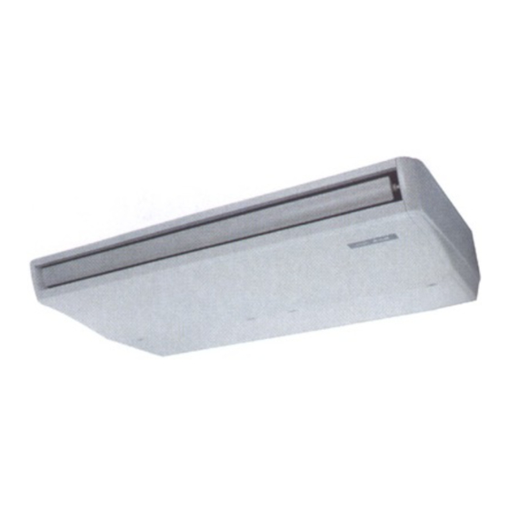
INDOOR UNIT
Ceiling Suspended
[Service Ref.]
PCH-2GKHA
PCH-2.5GKHA
PCH-3GKHA
PCH-4GKHSA
PCH-5GKHSA
PCH-6GKHSA
FILTER
CHECK MODE
TEST RUN
REMOTE CONTROLLER
This manual does not cover the
following outdoor units.
serving them, please refer to the
service manual No.OC128 and
this manual in a set.
[Service Ref.]
1
PUH-2VKA
1
PUH-2.5VKA
PUH-3VKA
1
PUH-3YKA
PUH-4YKSA
1
PUH-5YKSA
PUH-6YKSA
1
1
CONTENTS
1. FEATURES ···········································3
2. PART NAMES AND FUNCTIONS ········7
3. SPECIFICATIONS·································8
4. DATA ···················································11
5. OUTLINES AND DIMENSIONS··········15
6. WIRING DIAGRAM·····························20
7. REFRIGERANT SYSTEM DIAGRAM ······21
8. OPERATION FLOW-CHART ··············22
9. MICROPROCESSOR CONTROL·······26
10. TROUBLESHOOTING ························49
11. DISASSEMBLY PROCEDURE ···········57
12. PARTS LIST········································62
13. OPTIONAL PARTS ·····························73
The Slim Line.
From Mitsubishi Electric.
1997
No. OC135
When
2
2
2
2
3
3
2
Advertisement
Table of Contents

Related Manuals for Mitsubishi Electric PCH-2GKHA


Summary of Contents for Mitsubishi Electric PCH-2GKHA
-
Page 1: Table Of Contents
7. REFRIGERANT SYSTEM DIAGRAM ······21 8. OPERATION FLOW-CHART ··············22 INDOOR UNIT 9. MICROPROCESSOR CONTROL·······26 10. TROUBLESHOOTING ························49 11. DISASSEMBLY PROCEDURE ···········57 12. PARTS LIST········································62 FILTER CHECK MODE TEST RUN 13. OPTIONAL PARTS ·····························73 The Slim Line. From Mitsubishi Electric. REMOTE CONTROLLER... -
Page 3: Features
FILTER CHECK MODE TEST RUN Indoor unit Remote controller Cooling capacity/Heating capacity Service Ref. Btu/h PCH-2GKHA 5,400 / 6,200 (7,600) 18,400 / 21,200 (25,900) PCH-2.5GKHA 7,000 / 7,100 (9,200) 23,900 / 24,200 (31,400) PCH-3GKHA 7,500 / 8,500 (10,600) 25,600 / 29,000 (36,200) -
Page 4: Operation Lamp
Display CENTRALLY display CONTROLLED display The current time , start time and stop time can be displayed in tensecond This indicates when the unit is intervals by pressing the time switch controlled by optional features such button. The start time or stop time is as central control type remote always displayed during the timer controller. - Page 5 1. AIR OUTLET New PCH series models have 1 air outlet (auto vane switching of horizontal air flow / down flow by switched by auto vane) instead of 2 (horizontal,and down flows). Protruding portion A 2. EASY TO CLEAN ; FLOCKLESS VANE Unifies the air speed with the vane.
- Page 6 6. QUITENESS ; 43dB (HIGH NOTCH) New PCH series has No.1 quietness by changing the air course and the adapting the new shape air outlet. Auto vane Swing 7. EASY MAINTENANCE ; NO MAINTENANCE NECESSARY FOR 2500 HOURS The new longlife air filter can be used continuously 2500 hours without maintenance (at general office situation). 8.
-
Page 7: Part Names And Functions
PART NAMES AND FUNCTION Indoor (Main) Unit Left/right guide vanes Change the direction of airflow from the horizontal blower. Air outlet Long-life fillter Removes dust and foreigh matter from air coming in through the grille (Recommended cleaning interval : Approx, every 2,500 operating hours) Air intake Up/down guide vanes Intake grille... -
Page 8: Specifications
SPECIFICATIONS Rating Conditions (JIS B8616) Service Ref. PCH-2GKHA PCH-2.5GKHA Item Function Cooling Heating Cooling Heating Btu/h 18,400 21,200 (25,900) 23,900 24,200 (31,400) Capacity 5,400 6,200 (7,600) 7,000 7,100 (9,200) 2.30 2.32 (3.72) 2.59 2.36 (4.46) Total input Service Ref. PCH-2GKHA PCH-2.5GKHA... - Page 9 Rating Conditions (JIS B8616) Service Ref. PCH-3GKHA PCH-4GKHSA Item Function Cooling Heating Cooling Heating Btu/h 25,600 29,000 (36,200) 34,100 35,700 (44,900) Capacity 7,500 8,500 (10,600) 10,000 10,450 (13,150) Total input 3.28 3.07 (5.17) 3.36 3.35(6.05) Service Ref. PCH-3GKHA PCH-4GKHSA Power supply Single phase.
- Page 10 Rating Conditions (JIS B8616) Service Ref. PCH-5GKHSA PCH-6GKHSA Item Function Cooling Heating Cooling Heating Btu/h 42,300 47,400 (57,700) 49,500 51,200 (61,400) Capacity 12,400 13,900 (16,900) 14,500 15,000 (18,000) Total input 4.45 4.40 (7.40) 4.97 4.82 (7.82) Service Ref. PCH-5GKHSA PCH-6GKHSA Power supply Single phase.
-
Page 11: Data
2.37 2.52 5448 5299 5104 4897 4678 4447 1.88 1.96 2.12 2.27 2.43 2.58 5800 5648 5442 5226 5000 4764 PCH-2GKHA 1.92 2.00 2.16 2.33 2.49 2.66 6157 6012 5798 5574 5341 5099 1.95 2.04 2.21 2.38 2.56 2.75 6517... - Page 12 5546 1.93 6285 2.11 7082 2.31 7936 2.52 4066 1.71 4675 1.89 5337 2.08 6051 2.28 6816 2.49 7632 2.71 PCH-2GKHA 3907 1.81 4485 2.01 5125 2.22 5827 2.44 6590 2.67 7413 2.91 4862 1.61 5573 1.78 6351 1.96 7198 2.15...
- Page 13 3. ELECTRICAL DATA Rating Conditions (JIS B8616) Indoor …… 220V 50Hz 1phase Outdoor … 220V 50Hz 1phase / 380V 50Hz 3phase PCH-2GKHA PCH-2.5GKHA PCH-3GKHA PCH-4GKHSA PCH-5GKHSA PCH-6GKHSA Service Ref. Mode Cooling Heating Cooling Heating Cooling Heating Cooling Heating Cooling Heating...
- Page 14 4. STANDARD OPERATION DATA Rating Conditions (JIS B8616) Service Ref. PCH-2GKHA PCH-2.5GKHA PCH-3GKHA PCH-4GKHSA PCH-5GKHSA PCH-6GKHSA Cooling Heating Cooling Heating Cooling Heating Cooling Heating Cooling Heating Cooling Heating Mode 6,200 7,100 8,500 10,450 13,900 15,000 Capacity 5,400 7,000 7,500 10,000...
-
Page 15: Outlines And Dimensions
OUTLINES AND DIMENSIONS 1. INDOOR UNIT PCH-2GKHA... - Page 16 PCH-2.5GKHA PCH-3GKHA...
- Page 17 PCH-4GKHSA...
- Page 18 PCH-5GKHSA PCH-6GKHSA...
- Page 19 2. REMOTE CONTROLLER Unit : mm(inch) FILTER FILTER CHECK MODE CHECK MODE TEST RUN TEST RUN Rear side wiring arrangement opening. CAUTION SW18 SW17...
-
Page 20: Wiring Diagram
WIRING DIAGRAM PCH-2GKHA /PCH-2.5GKHA /PCH-3GKHA PCH-4GKHSA /PCH-5GKHSA /PCH-6GKHSA SYMBOL NAME SYMBOL NAME SYMBOL NAME FAN MOTOR CAPACITOR J9<I.B> MODEL SELECTOR JUMPER RESISTORS SW17<R.B> ADDRESS SELECTOR CN1<R.B> PROGRAM TIMER CONNECTOR LED1<I.B> DC 12V POWER LED SW18<R.B> FUNCTION SELECTOR CN2<R.B> REMOTE SWITCH CONNECTOR LED2<I.B>... -
Page 21: Refrigerant System Diagram
REFRIGERANT SYSTEM DIAGRAM Unit : mm PCH-2GKHA /PUH-2VKA Refrigerant flow in cooling PCH-2.5GKHA /PUH-2.5VKA Refrigerant flow in heating High pressure control switch <R.V.coil> PCH-3GKHA /PUH-3VKA ,PUH-3YKA Heating ON Oil separator Cooling OFF Outdoor unit Refrigerant pipe Service (option) 4-way valve... -
Page 22: Operation Flow-Chart
OPERATION FLOW-CHART MAIN OPERATION START Power circuit breaker Check SW ON twice Operation SW “OFF” timer Set time “ON” timer complete Set time complete Trouble Remote controller operation display STOP Trouble STOP Operating mode (COOL) COOL operation PROTECTION DEVICE PROTECTION DEVICE SELF HOLD RELEASE SELF HOLD Operating mode... - Page 23 COOLING OPERATION COOL operation Four-way valve/OFF Initial COOLING Vane intial setting Vane 40 deg downward angle 60 deg downward angle Fan speed Downward discharge 1 hour Vane horizontal Vane setting notch airflow Compressor thermostat Allowance cancel 3-minute time delay 6-minute Allowance time delay period...
-
Page 24: Heating Operation
HEATING OPERATION Heat operation PCH-GKH(S)A Initial Type Heating area HEATING Defrost release 3-minute Vane initial setting Vane setting notch Auxiliary heater Defrost 30 min. elapse Indoor coil Defrosting Outdoor unit trouble thermistor is 60!C or higher Four-way valve ON FAN speed Low notti Hor adjust in process... -
Page 25: Dry Operation
DRY OPERATION operation Four-way valve / OFF Initial dry operation Vane Vane initial setting setting notch Room tempereature is 18°C or lower During compressor ON 3-minute 3-minute compressor time delay operation Compressor & Compressor & thermostat thermostat ON 10-minute Compressor ON compressor time completes Compressor ON... -
Page 26: Microprocessor Control
MICROPROCESSOR CONTROL 1.OUTLINE OF MICROPROCESSOR CONTROL OUTPUT to remote controller INPUT to remote controller Remote controller board Processes and transmits orders.orders. OFF-ON switching. Remote controller COOL/DRY-AUTO-HEAT selector switching. LCD indicator Thermostat setting. TIMER mode selector-switching and Timer setting. FILTER HIGH-LOW fan speed switching. CHECK MODE TEST RUN AUTO Vane selector (AIR DISCHARGE) -
Page 27: Indoor Unit Control
2. INDOOR UNIT CONTROL 2-1COOL operation <How to operate> 1 Press POWER ON/OFF button. 2 Press the a button to display “ f ”. 3 Press the i TEMP button to set the desired temperature. NOTE: Set temperature changes 1°C when the FILTER button is pressed one time. - Page 28 5 Coil frost protection When indoor coil temperatuer becomes -15°C or below,coil frost protection will proceed as follows. <Start condition> After the compressor has been continuously operated for 3 minutes or more,and the indoor coil temperature has been - 15° or below for 3 minutes,the coil frost protection will start. <Coil frost protection>...
- Page 29 (3) Auto vane control Auto vane position is set to horizontal airflow at the start-up of COOL operation. It can then be changed by the remote controller. (a) Stop mode (fixed operation) ( i ) At start-up of COOL operation, the auto vane is set to 30 degrees airflow direction. ( ii ) Discharge direction can be changed with botton.
- Page 30 <Auto vane drive> (a) The auto vane is driven by DC12V motor. (b) Airflow direction is selected depends on the number of pulse were sended. (c) Before start driving the auto vane, detect the standard position first, output the number of pulse to each airflow. (d) The speed of the auto vane drive for both open and close are setted at 200 pulse/sec.
- Page 31 2-2 DRY operation <How to operate> 1 Press POWER ON/OFF button. 2 Press the a button to display “ e ”. FILTER 3 Press the i TEMP button to set the desired temperature. CHECK MODE TEST RUN NOTE: The set temperature changes 1°C when the button is pressed one time.
- Page 32 4The compressor will not start when the room temperature is below 18:. The compressor start intermittent operation when the power is turned ON with room temperature above 18;. The compres sor ON/OFF time depends on the themostat ON/OFF and the following room temperature. After 3-minute compressor operation.
- Page 33 2-3 HEAT operation <How to operate> 1 Press POWER ON/OFF button. 2 Press the a button to display “ g ”. 3 Press the i TEMP button to set the desired temperature. FILTER NOTE: The set temperature changes 1°C when the CHECK MODE TEST RUN button is pressed one time.
- Page 34 (1) Compressor control 13-minute time delay To prevent overload, the compressor will not start within 3 minutes after stop. 2The compressor runs when the room temperature is higher than the set temperature. The compressor stops when the room temperature is equal to or lower than the set temperature. 3The compressor stops in check mode or during protective functions.
- Page 35 (3) Auto vane control (a) STOP mode (fixed operation) ( i ) The airflow direction at the start-up of HEAT operation is the same as that of the previous operation. ( ii ) The airflow direction can be charged by the remote controller setting. 20°...
- Page 36 (6) Indoor coil thermistor abnormality detection An abnormality can be detected during compressor ON, except for the following. For the first 30 minutes after the temperature difference between the indoor coil temperature and room temperature enters the RANGE C. When the temperature difference enters the RANGE C until it moves to the RANGE B. (7) Defrosting operation After the outdoor unit starts the defrosting operation, when the temperature difference beetween the indoor coil temperature and room temperature gets out of RANGE A and into RANGE B, the indoor unit starts the defrosting mode.
- Page 37 2-4 AUTO operation (Automatic COOL/HEAT change over operation) <How to operate> 1 Press POWER ON/OFF button. 2 Press the button to display “ ” 3 Press the TEMP button to set the desired temperature. FILTER NOTE: The set temperature changes 1°C when the CHECK MODE TEST RUN button is pressed one time.
- Page 38 2-5 Auto vane control <How to operate> To change the air flow direction, press button. NOTE: Vane angle can be change to upper angle by cutting off the J5-3. FILTER (Jamper resistance of indoor units) CHECK MODE TEST RUN Horizontal 20˚...
- Page 39 2-6 TIMER operation <Timer function> AUTO STOP ·········The air conditioner stops after the set time lapses. AUTO START ········The air conditioner starts after the set time lapses. TIMER OFF ··········Timer is not active. <How to operate> FILTER 1. Press POWER ON/OFF button. CHECK MODE TEST RUN 2.
- Page 40 (1) Indoor coil temperature code During the test run, the indoor coil temperature code from 1 to 15 is displayed on the remote controller instead of room temperature. The code should fall with the lapse of time in normal COOL operation, and should rise in normal HEAT operation.
- Page 41 2-9 Interlock with ventilation system (LOSSNAY) Mr. SLIM/LOSSNAY interlock operation is available by using the optional parts listed below. (1) System organization Relay box (PZ-12RB-E) Relay box Mr. SLIM LOSSNAY Power supply LOSSNAY Mr. SLIM Power supply Remote display Remote adapter controller Remote...
- Page 42 2-10 Dip switch functions Each figure shows the initial factory setting. 1 On remote controller board (1) SW17(Address selector) 1 2 3 4 5 6 7 8 SW17-1~6) For address setting SW17-7) When two remote controllers are used,this switch sets the controller function. OFF:The remote controller is set as a main controller.
- Page 43 (2) SW2 (Address selector) Used insetting the unit-address for group control. 1 2 3 4 5 6 For further information, refer to page 40. (3) SW3 (Emergency operation switch) Normal operation For emergency cooling For emergency heating (4) J5 (Model selector emergency heating) J5-2) Provided : For models with heat pump.
- Page 44 The indoor fan relay turns ON. One second later, the phase control will start. (a) During fan OFF The phase control turns OFF. One second later, the indoor fan relay will turn OFF. 100% rotational Voltage frequency (rpm) Service Ref. 15Hz 1370 1380 PCH-2GKHA 1390 1350 1360 PCH-2.5GKHA 1370 1350 PCH-3GKHA 1360 1370...
-
Page 45: Outdoor Unit Control
3. OUTDOOR UNIT CONTROL 3-1 Outdoor fan control The rotational frequency of outdoor fan is phase-controlled according to the outdoor coil temperature. This control allows the cooling operation even with the low outside-air temperature and the heating operation even with the high outside-air temperature. - Page 46 3-5 Defrosting in HEAT mode <Defrosting time chart> Defrosting Defrosting starts. stops. Indoor unit Indoor fan 35degrees(SW5-3 OFF)or 20degrees(SW5-3:ON)discharge direction (Remote controller still displays set direction.) Auto vane Set direction Set direction Outdoor unit 4-way valve Bypass valve Outdoor fan Compressor (1) Start conditions A.
- Page 47 (3) Defrost interval The defrost interval time is determined as follows. Initial defrost interval is 50 minutes. The defrost interval after defrosting depends on the preceding defrosting time as shown below. Defrosting operation time Next defrost interval 3 minutes or below 120 minutes 3 to 7 minutes 80 minutes...
- Page 48 3-7 Service functions (1) Compulsory defrositng 1When all of the following conditions are satisfied, pressing SW2 starts the compulsory defrosting. During HEAT mode The compressor is ON. The outdoor coil temperature is being displayed by LED. (Outdoor controller board dip switch SW3-1 : OFF, SW3-2 : The outdoor coil thermistor reads 8°C or below.
-
Page 49: Troubleshooting
TROUBLESHOOTING 1.TROUBLES IN TEST RUN Symptom Cause Check points The display “CENTRALLY 1) Wrong address setting of remote 1) Check the address setting of remote controller CONTROLLED” on remote controller/indoor controller board. and indoor controller. controller dose not 2) Timer adapter is connected to the 2) Make sure the timer adapter is used correctly. - Page 50 2. SELF DIAGNOSTIC FUNCTION WITH REMOTE CONTROLLER 2-1 When malfunction occurs during operation When a malfunction occurs, the indoor and outdoor units stop and the malfunction is displayed on the LCD of the remote controller. (1) ON the set temperature display part, “CHECK” appears, and the unit CHECK mode address and the check code are diplayed alternately at one-second intervals.
- Page 51 Check Diagnosis of malfunction Cause Check points code Signal transmitting/receiving During individual unit control 1) Check the transmission wire. error 1) Bad contact of transmission 2) Check with another remote controller. If “EO” is (Indoor controller does not wire still indicated, replace the indoor controller respond to remote controller 2) Signal transmitting/receiving board.
- Page 52 3. SERVICE DATA INDICATION BY SWITCHES ON OUTDOOR CONTROLLER BOARD Setting dip switchs SW2 and SW3 on the outdoor controller board enables LED to show the output state and check code. Output state is shown by LED lighting, and check code by blinking. SW1 : Turning SW1 ON clears the check code.
- Page 53 3-1 Outdoor coil temperature To obtain data on the outdoor coil temperature, add the number of bits of lighting LEDs, and see the graph below to find the temperature. (Short 238 bits) (Short 238 bits) (Open 8 bits) (Open 8 bits) Number of bits 3-2 Fan output step To obtain data on the fan output step, add the number of bits of lighting LEDs, and see the graph below to find the fan...
- Page 54 4. TROUBLESHOOTING ACCORDING TO CHECK CODE Blinking Diagnosis of malfunction Cause Check point Reversed phase Phases L , and L Check the power supply connection. connected improperly. Open phase Phase L is open. Check the power supply. Contact of protector, such as Check each protector.
- Page 55 6. WRONG WIRING ON SITE 6-1 Between remote controller and indoor unit If the wire is disconnected between the remote controller and the indoor unit, nothing is displayed on the remote controller when the POWER button is pressed. The beep sound will also not be heard. 6-2 Phenomenon due to wrong wiring between indoor and outdoor units Wrong wiring Mode Thermostat...
- Page 56 7. OTHER TROUBLES AND CAUSES Vanes do not work. Vane motor does not work. Vane motor is damaged. Connector is poorly connected. Vane motor is poorly assembled. Indoor controller board is damaged. Unit stops after 5 to Refer to check code on remote controller display. Protection function is working.
-
Page 57: Disassembly Procedure
DISASSEMBLY PROCEDURE PCH-3GKHA OPERATING PROCEDURE PHOTOS&ILLUSTRATIONS 1. Removing the air intake grill Figure 1 (1) Slide the intake grill holding knobs (at two locations) backward to open the intake grill. (2) When the intake grill left open, push the stoppers on the rear hinges (at two locations) to pull out the intake grill. - Page 58 OPERATING PROCEDURE PHOTOS&ILLUSTRATIONS 3. Removing the fan motor Photo 2 (1) Remove the intake grill. Motor gurd (2) Disconnect the fan motor connector. Screws (3) Unscrew screws for removing the motor guard. Motor (4) Unscrew screws for removing the fan guard. (5) Remove the screw for removing the motor support at both Set screws left and right side.
- Page 59 OPERATING PROCEDURE PHOTOS 6. Removing the vane motor Photo 4 Relay connector of Check (1) Remove the air intake grill. the pipe thermistor Screw panel (2) Remove the left side panel. (3) Remove the relay connector of vane motor. (4) Remove the electrical box. (5) Remove the screws of vane motor, then remove vane motor.
- Page 60 OPERATING PROCEDURE PHOTOS 9. Removing the drain pan (option) Photo 8 (1) Remove the air intake grill. (2) Remove the beam. (3) Remove the side panel (right and left). (4) Remove the under panel. Remove the screws of the right and left side drain pan.
- Page 61 OPERATING PROCEDURE PHOTOS 12. Removing the support heater. Photo 11 (1) Remove the air intake grill. (2) Remove the beam. (3) Remove the side panel (right and left). Screws (4) Remove the relay connector for the pipe thermistor. (5) Remove the under panel. (6) Remove the drain pan.
Need help?
Do you have a question about the PCH-2GKHA and is the answer not in the manual?
Questions and answers