Table of Contents
Advertisement
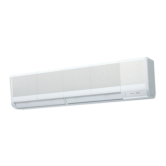
SPLIT-TYPE, HEAT PUMP AIR CONDITIONERS
TECHNICAL & SERVICE MANUAL
<Indoor unit>
[Model names]
PKFY-P63VFM-E
PKFY-P100VFM-E
[Service Ref.]
PKFY-P63VFM-E
PKFY-P100VFM-E
REVISED EDITION-A
Revision:
• RoHS PARTS LIST is added.
• Some descriptions have
been modified.
• Please void OC356.
Note:
• This manual describes only
service data of the indoor
units.
• RoHS compliant products
have <G> mark on the spec
name plate.
• For servicing of RoHS com-
pliant products, refer to the
RoHS Parts List.
CONTENTS
1. SAFETY PRECAUTION····························2
2. PART NAMES AND FUNCTIONS ············6
3. SPECIFICATIONS·····································8
4. OUTLINES AND DIMENSIONS ··············11
5. WIRING DIAGRAM ·································13
7. TROUBLE SHOOTING ···························15
8. DISASSEMBLY PROCEDURE ···············22
9. PARTS LIST············································25
10. RoHS PARTS LIST ·································28
July 2006
No. OC356
Advertisement
Table of Contents

Subscribe to Our Youtube Channel
Related Manuals for Mitsubishi Electric PKFY-P63VFM-E


Summary of Contents for Mitsubishi Electric PKFY-P63VFM-E
-
Page 1: Table Of Contents
REVISED EDITION-A TECHNICAL & SERVICE MANUAL <Indoor unit> Revision: [Model names] [Service Ref.] • RoHS PARTS LIST is added. • Some descriptions have PKFY-P63VFM-E been modified. PKFY-P63VFM-E PKFY-P100VFM-E • Please void OC356. PKFY-P100VFM-E Note: • This manual describes only service data of the indoor units. -
Page 2: Safety Precaution
SAFETY PRECAUTION CAUTIONS RELATED TO NEW REFRIGERANT Cautions for units utilizing refrigerant R407C Do not use the existing refrigerant piping. Use liquid refrigerant to seal the system. The old refrigerant and lubricant in the existing piping If gas refrigerant is used to seal the system, the composition contains a large amount of chlorine which may cause the of the refrigerant in the cylinder will change and performance lubricant deterioration of the new unit. - Page 3 [3] Service tools Use the below service tools as exclusive tools for R407C refrigerant. Tool name Specifications Gauge manifold ·Only for R407C. ·Use the existing fitting SPECIFICATIONS. (UNF7/16) ·Use high-tension side pressure of 3.43MPa·G or over. Charge hose ·Only for R407C. ·Use pressure performance of 5.10MPa·G or over.
- Page 4 Cautions for units utilizing refrigerant R410A Use a vacuum pump with a reverse flow check Do not use the existing refrigerant piping. valve. The old refrigerant and lubricant in the existing piping Vacuum pump oil may flow back into refrigerant cycle and contains a large amount of chlorine which may cause the that can cause deterioration of refrigerant oil etc.
- Page 5 [1] Cautions for service (1) Perform service after collecting the refrigerant left in unit completely. (2) Do not release refrigerant in the air. (3) After completing service, charge the cycle with specified amount of refrigerant. (4) When performing service, install a filter drier simultaneously. Be sure to use a filter drier for new refrigerant.
-
Page 6: Part Names And Functions
PART NAMES AND FUNCTIONS Indoor Unit PKFY-P63VFM-E PKFY-P100VFM-E Air intake Filter Air intake grille (Removes dust and dirt from the intake air.) Room air is suctioned in here. Guide vane Auto vane Air flow can be changed to horizontally by moving the Guide vane to the left or right. - Page 7 Display “Sensor” indication Displayed when the remote controller sensor is used. Day-of-Week For purposes of this explanation, Shows the current day of the week. all parts of the display are shown as lit. During actual operation, only Time/Timer Display the relevant items will be lit. “Locked”...
-
Page 8: Specifications
SPECIFICATIONS 3-1. SPECIFICATION Unit PKFY-P63VFM-E PKFY-P100VFM-E Item Power source [,V,Hz Single phase, 220-230-240V, 50Hz / 220V, 60Hz Cooling capacity 11.2 Heating capacity 12.5 0.12 0.14 Cooling Input Heating 0.12 0.14 Cooling 0.55 0.64 Current 0.55 0.64 Heating — Plastic , white : <3.4Y 7.7/0.8>... - Page 9 3-2. ELECTRICAL PARTS SPECIFICATIONS Service Ref. PKFY-P63VFM-E PKFY-P100VFM-E Symbol Parts name TH21 Room temperature thermistor Resistance 0°C/15kΩ, 10°C/9.6kΩ, 20°C/6.3kΩ, 25°C/5.2kΩ, 30°C/4.3kΩ, 40°C/3.0kΩ TH22 Liquid pipe temperature thermistor Resistance 0°C/15kΩ, 10°C/9.6kΩ, 20°C/6.3kΩ, 25°C/5.2kΩ, 30°C/4.3kΩ, 40°C/3.0kΩ TH23 Gas pipe temperature thermistor Resistance 0°C/15kΩ, 10°C/9.6kΩ, 20°C/6.3kΩ, 25°C/5.2kΩ, 30°C/4.3kΩ, 40°C/3.0kΩ...
-
Page 10: Noise Criterion Curves
3-3. NOISE CRITERION CURVES PKFY-P63VFM-E PKFY-P100VFM-E NOTCH SPL(dB) LINE NOTCH SPL(dB) LINE High High NC-70 NC-70 NC-60 NC-60 NC-50 NC-50 NC-40 NC-40 NC-30 NC-30 APPROXIMATE APPROXIMATE TERESHOLD OF TERESHOLD OF HEARING FOR HEARING FOR NC-20 NC-20 CONTINUOUS CONTINUOUS NOISE NOISE... -
Page 11: Outlines And Dimensions
OUTLINES AND DIMENSIONS PKFY-P63VFM-E Unit : mm... - Page 12 PKFY-P100VFM-E Unit : mm...
-
Page 13: Wiring Diagram
WIRING DIAGRAM PKFY-P63VFM-E PKFY-P100VFM-E Symbol Symbol Symbol Name Name Name Capacitor (fan motor) Indoor controller board TH23 Pipe temp.detection/Gas Thermistor Linear expansion valve (0°C/15t,25°C/5.4t) CN32 Connector Remote switch Fan motor (with inner thermo) CN41 HA terminal-A Circuit board Centrally control... -
Page 14: Refrigerant System Diagram
REFRIGERANT SYSTEM DIAGRAM PKFY-P63VFM-E PKFY-P100VFM-E Gas pipe temperature Strainer (#50mesh) thermistor TH23 Gas pipe Liquid pipe temperature thermistor TH22 Flare connection Liquid pipe Heat exchanger Linear expansion valve Strainer (#100mesh) Strainer (#100mesh) Room temperature thermistor TH21 Capacity PKFY-P100VFM-E PKFY-P63VFM-E Item Gas pipe {15.88 (5/8") -
Page 15: Trouble Shooting
TROUBLE SHOOTING 7-1. HOW TO CHECK PKFY-P63VFM-E PKFY-P100VFM-E Parts name Check points Room temperature Disconnect the connector then measure the resistance using a tester. thermistor (TH21) (Surrounding temperature 10:~30:) Liquid pipe temperature thermistor (TH22) Normal Abnormal (Refer to the next page for a detail.) 4.3k"~9.6k"... - Page 16 <Thermistor Characteristic graph> < Thermistor for lower temperature > Room temperature thermistor(TH21) Thermistor for Liquid pipe temperature thermistor (TH22) lower temperature Gas pipe temperature thermistor (TH23) Thermistor R =15k' ± 3% Fixed number of B=3480 ± 2% Rt=15exp { 3480( 273+t 15k' 9.6k'...
- Page 17 <Output pulse signal and the valve operation> Output Output (Phase) Closing a valve : 1 Opening a valve : 4 The output pulse shifts in above order. 1. When linear expansion valve operation stops, all output phase become OFF. 2. At phase interruption or when phase does not shift in order, motor does not rotate smoothly and motor locks and vibrates.
-
Page 18: Indoor Unit
Vane cooling limit angle setting w4 Horizontal angle Down B,C Selection hour. w5 sw3-9 setting Indoor linear expansion Effective Not effective PKFY-P63VFM-E = ON valve opening PKFY-P100VFM-E = OFF Heater 4degrees up Not effective Effective Target Superheat setting w5 9degrees 6degrees... - Page 19 Switch Pole Operation by switch Remarks Address board SW11 1st digit Address can be set while the address unit is stopped. setting SW12 SW11 Address setting should be done when M-NET <At delivery> remote controller is being used. SW12 SW12 SW11 2nd digit address...
- Page 20 7-3. TEST POINT DIAGRAM 7-3-1. Indoor controller board PKFY-P63VFM-E PKFY-P100VFM-E CN29 Pipe temperature CN2D CN2M CN3A thermistor/Gas (TH23) Connect to the indoor Connect to the terminal block (TB5) Connect to the terminal block (TB15) power board (CN2S) (M-NET transmission connecting wire) (MA-Remote controller connecting wire) 12.5-13.7V DC (Pin1 1 (+))
- Page 21 7-3-2. Indoor power board PKFY-P63VFM-E PKFY-P100VFM-E CN2S Connect to the indoor power board (CN2D) Between 1 1 to 3 3 12.6-13.7V DC (Pin1 1 (+)) CNSK Connect to the indoor controller board (CNDK) Between 1 1 to 3 3 220-240V AC...
-
Page 22: Disassembly Procedure
DISASSEMBLY PROCEDURE PKFY-P63VFM-E PKFY-P100VFM-E OPERATING PROCEDURE PHOTOS & ILLUSTRATION 1. Removing the lower side of the indoor unit from the instal- Figure 1 lation plate Hanger of indoor unit (1) Remove the 2 screws. Hang the indoor unit hangers to the catches on the instal- Catch of installation plate lation plate. - Page 23 OPERATING PROCEDURE PHOTOS & ILLUSTRATION (7) Remove the indoor controller board case. Photo 3 Then the Power board and the capacitor can be serviced. Capacitor Power board Terminal block Electrical parts box 5. Removing the vane motor Photo 4 (1) Remove the right side panel. Indoor controller board (2) Remove the screw of the electrical parts box cover, and remove the terminal cover.
- Page 24 OPERATING PROCEDURE PHOTOS 8. Removing the lineflow fan and the fan motor Photo 7 (1) Remove the left and right side panels. (2) Remove the grilles. (3) Remove the electrical parts box. Screw Lineflow fan (4) Remove the drain pan. (5) Loosen the screw that fixes the lineflow fan to the fan Fan motor motor.
-
Page 25: Parts List
PARTS LIST (non-RoHS compliant) STRUCTURAL PARTS PKFY-P63VFM-E PKFY-P100VFM-E Part number that is circled is not shown in the figure. Q'ty / set Price Wiring Recom- Remarks PKFY-P•VFM-E Part No. Part Name Specification Diagram mended (Drawing No.) Symbol Q'ty Unit Amount... - Page 26 ELECTRICAL PARTS PKFY-P63VFM-E PKFY-P100VFM-E 36 35 TEMP. ON/OFF Q'ty / set Price Wiring Recom- Remarks Part No. Part Name Specification PKFY-P•VFM-E Diagram mended (Drawing No.) Symbol Q'ty Unit Amount R01 Z61 102 BEARING MOUNT R01 005 103 SLEEVE BEARING R01 13G 114...
- Page 27 Part number that is circled is not shown in the figure Q'ty / set Price Wiring Recom- Remarks Part No. Part Name Specification PKFY-P•VFM-E Diagram mended (Drawing No.) Symbol Q'ty Unit Amount T7W E03 223 VANE MOTOR R01 E32 202 GAS PIPE THERMISTOR TH23 T7W E12 202...
-
Page 28: Rohs Parts List
RoHS PARTS LIST ELECTRICAL PARTS PKFY-P63VFM-E PKFY-P100VFM-E 36 35 TEMP. ON/OFF Q'ty / set Price Recom- Wiring Remarks Part No. Part Name Specification Diagram mended PKFY-P•VFM-E (Drawing No.) Symbol Q'ty Unit Amount R01 Z61 102 BEARING MOUNT R01 E04 103... - Page 29 Part number that is circled is not shown in the figure Q'ty / set Price Wiring Recom- Remarks Part No. Part Name Specification PKFY-P•VFM-E Diagram mended (Drawing No.) Symbol Q'ty Unit Amount T7W E05 223 VANE MOTOR R01 H15 202 GAS PIPE THERMISTOR TH23 ROOM TEMPERATURE THERMISTOR...
- Page 30 STRUCTURAL PARTS PKFY-P63VFM-E PKFY-P100VFM-E Part number that is circled is not shown in the figure. Q'ty / set Price Wiring Recom- Remarks PKFY-P•VFM-E Part No. Part Name Specification Diagram mended (Drawing No.) Symbol Q'ty Unit Amount R01 14G 662 LEFT SIDE PANEL...
- Page 32 HEAD OFFICE : TOKYO BLDG., 2-7-3, MARUNOUCHI, CHIYODA-KU, TOKYO100-8310, JAPAN cCopyright 2005 MITSUBISHI ELECTRIC ENGINEERING CO., LTD. Distributed in Jul. 2006 No. OC356 REVISED EDITION-A PDF 8 New publication, effective Jul. 2006 Distributed in Nov. 2005 No. OC356 PDF 9...
Need help?
Do you have a question about the PKFY-P63VFM-E and is the answer not in the manual?
Questions and answers