Mitsubishi Electric PKFY-P15VBM-E Technical & Service Manual
Series pkfy wall mounted r410a/r407c/r22
split-type, heat pump air conditioners
Hide thumbs
Also See for PKFY-P15VBM-E:
- Technical & service manual (28 pages) ,
- Operation manual (40 pages) ,
- Operation manual (32 pages)
Table of Contents
Advertisement
SPLIT-TYPE, HEAT PUMP AIR CONDITIONERS
TECHNICAL & SERVICE MANUAL
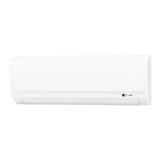
Indoor unit
[Model names]
PKFY-P15VBM-E
PKFY-P20VBM-E
PKFY-P25VBM-E
INDOOR UNIT
[Service Ref.]
PKFY-P15VBM-E
PKFY-P20VBM-E
PKFY-P20VBM-ER1
PKFY-P25VBM-E
PKFY-P25VBM-ER1
Model name
indication
R410A
R407C
CONTENTS
1. TECHNICAL CHANGES ......................... 2
2. SAFETY PRECAUTION .......................... 2
3. PART NAMES AND FUNCTIONS .......... 6
4. SPECIFICATION ..................................... 9
5. OUTLINES AND DIMENSIONS ............ 11
6. WIRING DIAGRAM ............................... 12
7. REFRIGERANT SYSTEM DIAGRAM ........ 14
8. TROUBLESHOOTING .......................... 14
9. DISASSEMBLY PROCEDURE ............. 21
PARTS CATALOG (OCB418)
November 2008
No. OCH418
REVISED EDITION-A
R22
Revision:
• PKFY-P15VBM-E and PKFY-
P20/25VBM-ER1 are added
in REVISED EDITION-A.
• Some descriptions have
been modified.
• Plase void OCH418.
Note:
• This manual describes only
service data of the indoor
units.
• RoHS compliant products
have <G> mark on the spec
name plate.
Advertisement
Table of Contents

Related Manuals for Mitsubishi Electric PKFY-P15VBM-E


Summary of Contents for Mitsubishi Electric PKFY-P15VBM-E
-
Page 1: Table Of Contents
REVISED EDITION-A TECHNICAL & SERVICE MANUAL R410A R407C Indoor unit [Model names] [Service Ref.] Revision: PKFY-P15VBM-E • PKFY-P15VBM-E and PKFY- PKFY-P15VBM-E P20/25VBM-ER1 are added PKFY-P20VBM-E in REVISED EDITION-A. PKFY-P20VBM-E • Some descriptions have PKFY-P20VBM-ER1 been modified. • Plase void OCH418. -
Page 2: Technical Changes
TECHNICAL CHANGES PKFY-P20VBM-E PKFY-P20VBM-ER1 PKFY-P25VBM-E PKFY-P25VBM-ER1 INDOOR CONTROLLER BOARD (I.B.) has been changed. SAFETY PRECAUTION CAUTIONS RELATED TO NEW REFRIGERANT Cautions for units utilizing refrigerant R407C Do not use the existing refrigerant piping. Use liquid refrigerant to charge the system. The old refrigerant and lubricant in the existing piping If gas refrigerant is used to seal the system, the composition contain a large amount of chlorine which may cause the... - Page 3 [2] Refrigerant recharging (1) Refrigerant recharging process 1 Direct charging from the cylinder. ·R407C cylinder available on the market has a syphon pipe. ·Leave the syphon pipe cylinder standing and recharge it. (By liquid refrigerant) Unit Gravimeter (2) Recharge in refrigerant leakage case ·After recovering the all refrigerant in the unit, proceed to working.
- Page 4 Cautions for units utilizing refrigerant R410A Use a vacuum pump with a reverse flow check Do not use the existing refrigerant piping. valve. The old refrigerant and lubricant in the existing piping Vacuum pump oil may flow back into refrigerant cycle and contains a large amount of chlorine which may cause the that can cause deterioration of refrigerant oil etc.
- Page 5 [1] Cautions for service (1) Perform service after collecting the refrigerant left in unit completely. (2) Do not release refrigerant in the air. (3) After completing service, charge the cycle with specified amount of refrigerant. (4) When performing service, install a filter drier simultaneously. Be sure to use a filter drier for new refrigerant.
-
Page 6: Part Names And Functions
PART NAMES AND FUNCTIONS Indoor unit Air intake Filter Grille Vane Louver Air outlet... -
Page 7: Wired Remote Controller
Wired remote controller “Sensor” indication Display Section Displayed when the remote controller sensor is used. Day-of-Week For purposes of this explanation, Shows the current day of the week. all parts of the display are shown as lit. During actual operation, only Time/Timer Display the relevant items will be lit. -
Page 8: Wireless Remote Controller
Wireless remote controller CHECK TEST RUN display CHECK and TEST RUN display indicate that the unit is being checked or test-run. MODEL SELECT display Blinks when model is selected. display Lights up while the signal is transmitted to the indoor unit when the button is pressed. display SET TEMP. -
Page 9: Specification
SPECIFICATION 4-1. SPECIFICATIONS Model PKFY-P20VBM-E(R1) PKFY-P25VBM-E(R1) PKFY-P15VBM-E Power source 1-phase 220-240V 50Hz, 1-phase 220V 60Hz Cooling capacity (Nominal) kcal/h 1,450 1,900 2,400 5,800 7,500 9,600 Btu/h kcal/h 1,500 2,000 2,500 Power input 0.04 0.04 0.04 Current input 0.20 0.20 0.20... - Page 10 4-2. ELECTRICAL PARTS SPECIFICATIONS Model PKFY-P15VBM-E Symbol PKFY-P20VBM-E(R1) PKFY-P25VBM-E(R1) Parts name Room temperature TH21 Resistance 0 /15k , 10 /9.6k , 20 /6.3k , 25 /5.4k , 30 /4.3k , 40 /3.0k thermistor Liquid pipe thermistor TH22 Resistance 0 /15k , 10 /9.6k , 20 /6.3k , 25 /5.4k , 30 /4.3k , 40 /3.0k...
-
Page 11: Outlines And Dimensions
OUTLINES AND DIMENSIONS PKFY-P15, 20, 25VBM-E Unit : mm PKFY-P20, 25VBM-ER1 11 11... -
Page 12: Wiring Diagram
WIRING DIAGRAM PKFY-P20, 25VBM-E Legend Symbol Symbol Symbol Name Name Name Vane motor Indoor controller board Voltage selection Switch Linear expansion valve CN32 Connector Remote switch SW11 Address setting 1s digit Centrally control Power supply Address setting 10ths digit CN51 SW12 Terminal block... - Page 13 PKFY-P15VBM-E PKFY-P20, 25VBM-ER1 Legend Symbol Symbol Symbol Name Name Name Vane motor Indoor controller board Voltage selection Switch CN32 Linear expansion valve Connector Remote switch SW11 Address setting 1s digit Centrally control Power supply Address setting 10ths digit CN51 SW12...
-
Page 14: Refrigerant System Diagram
Heat exchanger (#100mesh) Linear expansion valve Room temperature thermistor Strainer TH21 (#100mesh) Unit: mm(inch) Models PKFY-P15VBM-E PKFY-P20VBM-E(R1) PKFY-P25VBM-E(R1) Item {12.7 (1/2”) Gas pipe {6.35 (1/4”) Liquid pipe TROUBLESHOOTING 8-1. HOW TO CHECK THE PARTS PKFY-P15VBM-E PKFY-P20VBM-E(R1) PKFY-P25VBM-E(R1) Parts name Check points Room temperature Disconnect the connector then measure the resistance using a tester. - Page 15 <Thermistor Characteristic graph> < Thermistor for lower temperature > Room temperature thermistor (TH21) Thermistor for Liquid pipe temperature thermistor (TH22) lower temperature Gas pipe temperature thermistor (TH23) Thermistor R =15k' ± 3% Fixed number of B=3480 ± 2% Rt=15exp { 3480( 273+t 15k' 9.6k'...
- Page 16 <Output pulse signal and the valve operation> Output Output Closing a valve : 1 → 2 → 3 → 4 → 1 (Phase) Opening a valve : 4 → 3 → 2 → 1 → 4 The output pulse shifts in above order. •...
- Page 17 8-2. FUNCTION OF DIP SWITCH PKFY-P15VBM-E PKFY-P20VBM-E(R1) PKFY-P25VBM-E(R1) Operation by switch Effective Switch Pole Function Remarks timing Thermistor<Intake temperature> Indoor unit Built-in remote controller Address board position Filter clogging Provide Not provide <Initial setting> Filter sign indication 2,500 hr 100 hr...
- Page 18 Effective Switch Operation by switch Remarks timing SW11 Address board SW12 SW11 1s digit How to set address address <Initial setting> Example : If address is "3", remain SW12 setting SW12 SW11 (for over 10) at "0", and match SW11 (for 1 to 9) SW12 with "3".
- Page 19 8-3. TEST POINT DIAGRAM 8-3-1. Indoor controller board PKFY-P15VBM-E PKFY-P20VBM-E(R1) PKFY-P25VBM-E(R1) CN29 Pipe temperature CN5V CN81 CN90 thermistor/Gas (TH23) Vane motor output Connected to the Connected to the wireless (MV) address board (CN82) remote controller board (W.B) CN21 CN60 Pipe temperature...
- Page 20 8-3-2. Indoor power board Fan motor output (MF) Power supply for PKFY-P15VBM-E indoor controller board Between 1 to 3 220-240V AC PKFY-P20VBM-E(R1) PKFY-P25VBM-E(R1) CN2M FUSE Connected to the terminal block (TB5) 6.3A 250V (M-NET transmission connecting wire) 24-30V DC (non-polar)
-
Page 21: Disassembly Procedure
DISASSEMBLY PROCEDURE PKFY-P15VBM-E PKFY-P20VBM-E(R1) PKFY-P25VBM-E(R1) Be careful when removing heavy parts. OPERATION PROCEDURE PHOTOS & ILLUSTRATIONS 1. REMOVING THE LOWER SIDE OF THE INDOOR UNIT Figure 1 Figure 2 FROM THE INSTALLATION PLATE When there is removing plate (1) Remove the corner box at right lower side of the indoor unit and remove the removing plate from the corner box. - Page 22 OPERATION PROCEDURE OPERATION PROCEDURE PHOTOS & ILLUSTRATIONS PHOTOS & ILLUSTRATIONS 3. REMOVING THE INDOOR CONTROLLER BOARD AND Electrical box cover Photo 2 INDOOR POWER BOARD (1) Remove the front panel. (Refer to 2) (2) Remove the electrical box cover (screw 4 × 10). (Refer to the Photo 2) INDOOR CONTROLLER BOARD (1) Disconnect the following connectors on the indoor...
- Page 23 OPERATION PROCEDURE PHOTOS & ILLUSTRATIONS 5. REMOVING THE NOZZLE ASSEMBLY AND DRAIN HOSE Photo 5 (1) Remove the front panel (Refer to 2). Heat exchanger Electrical box (2) Remove the electrical box cover. (3) Disconnect the connector (CN5V) on the indoor controller Drain hose board.
- Page 24 HEAD OFFICE : TOKYO BLDG., 2-7-3, MARUNOUCHI, CHIYODA-KU TOKYO 100-8310, JAPAN cCopyright 2007 MITSUBISHI ELECTRIC ENGINEERING CO., LTD. New publication, effective Nov. 2008 Distributed in Nov. 2008 No. OCH418 REVISED EDITION-A PDF 7 Specifications subject to change without notice Distributed in May 2007 No. OCH418 PDF 9...
Need help?
Do you have a question about the PKFY-P15VBM-E and is the answer not in the manual?
Questions and answers