
Summary of Contents for LockUP Employee Lock
-
Page 1: User Manual
L OCK LockUp Lock - Employee Lock Shared Use Functionality... -
Page 2: Table Of Contents
Table of Contents Metal Door Installations __________________________________________ 2 Required Components __________________________________________ 3 Metal Door Mounting Types _ ____________________________________ 4 Surface Mount Metal Door Installation _ _________________________ 5 Recessed Cup Metal Door Installation ___________________________ 7 3-Hole Lock Plug Removal ______________________________________ 9 Padlock Hasp Removal _ _________________________________________ 10 Programming Instructions ______________________________ 12 Lock Interface Overview ________________________________________ 13 Key Guide _____________________________________________________ 13 Initializing Locks ______________________________________________ 14 Adding Additional Manager Flex Key(s) to a Lock System____________ 14 For Lost or Stolen Keys ________________________________________ 15 Shared Use Instructions _________________________________ 16 Operate with a User Code _______________________________________ 17... - Page 3 (iii) such defect has not been caused by corrosion, exposure to moisture, or ordinary wear and tear. LockUp lock products are not designed or intended for exterior use or where exposed to moisture. Any exterior use where exposed to moisture is not covered by any warranties and voids any warranties.
-
Page 5: Metal Door Installations
Metal Door Installations Required Components Metal Door Mounting Types Surface Mount Metal Door Installation Recessed Cup Metal Door Installation 3-Hole Lock Plug Removal Padlock Hasp Removal... - Page 6 Required Components LockUp Lock Parts Note: Confirm that all lock parts are present. If there are damaged or missing parts contact your LockUp Product Support Specialist. 1-Front Unit 1-Rear Unit 2-Locking Nuts Optional-Back Plate Required Tools For lock installation For padlock hasp removal 3/8”...
- Page 7 Metal Door Mounting Types LockUp is compatible with a majority of industry standard 3-hole configuration, latch and handle types. Some door types may need disassembly or modifications prior to installation. Recessed Cup with Single Point Latch Standard Lift Multi-Point Latch...
- Page 8 Surface Mount Metal Door Installation Parts 1-Front Unit 1-Rear Unit 2-Locking Nuts Required Tools 3/8” Socket (deep socket required) Surface Mount Metal Door Installation Steps Note: Prior to installation the door must be clear of any obstructions. See page 9 for door prep. Step 1 Step 2 Place the mounting screw posts of the front unit (A)
- Page 9 Step 3 Step 4 Slide the front unit (A) and rear unit (B) together Place the locking nuts (C) over the mounting screws making sure that the pins of the rear unit align with the and tighten to secure the lock to the door. front unit (A) connector.
- Page 10 Recessed Cup Metal Door Installation Parts 1-Front Unit 1-Rear Unit 2-Locking Nuts Required Tools 3/8” Socket (deep socket required) Recessed Cup Metal Door Installation Steps Note: Prior to installation the door must be clear of any obstructions. See page 9 for door prep. Step 1 Step 2 Place the mounting screw posts of the front unit (A)
- Page 11 Step 3 Step 4 Slide the front unit (A) and rear unit (C) together Place the locking nuts (D) over the mounting screw making sure that the pins of the rear unit connector align posts and hand tighten to secure the lock to the door. with the female connector of the front unit (A).
- Page 12 Door Prep - 3-Hole Lock Plug Removal Most metal lockers will come with a 3 point dial combo metal plug. This will need to be removed in order to install your LockUp Lock. Single or Standard Lift with Mounted Plug...
- Page 13 Note: LockUp manufactures an optional Back Plate to cover the padlock hasp hole. For more information please contact your LockUp Product Specialist.
-
Page 15: Programming Instructions
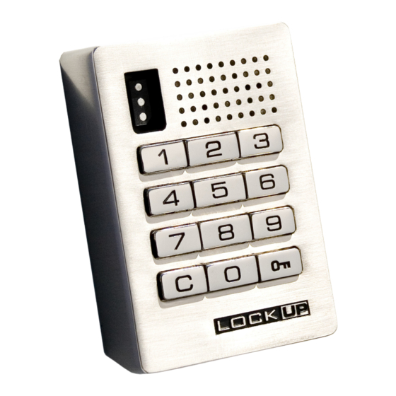
Programming Instructions Lock Interface Overview Key Guide Initializing Locks Ordering Manager Flex Key(s) For Lost or Stolen Keys... - Page 16 Lock Interface Overview Key Insert LED Usage Indicator Key Insertion Numeric Keypad LockUp Logo must be upright and facing to the left Pull Handle C Button Key Symbol Button Key Guide: Manager Flex Key (black) ADA User Key (Blue) • Provides management access •...
- Page 17 Manager Flex Key(s) and is now initialized. Ordering Manager Flex Key(s) Contact your LockUp Product Support Specialist to order an additional Manager Flex Key. Request that the additional Manager Flex Key(s) -“Match Previous” issued key(s). Your additional key(s) will automatically work with your lock system.
- Page 18 Replacing Lost or Stolen Keys For a Lost/Stolen Manager Flex Key Contact your LockUp Product Support Representative to order a replacement Manager Flex Key. 1) Go to a lock 1) While the lock is in the unlocked position, touch the...
-
Page 19: Operate With A User Code
Lock Use Instructions Operate with a User Code Operate with an ADA User Key Operate with a Manager Flex Key... - Page 20 Operate with a User Code To Lock To Unlock 1) Find an available lock 1) At same lock 2) Press: 2) Press: _ _ _ _ _ _ _ _ (any four-digit code) (same code used to lock) Note: If an incorrect User Code is entered three consecutive times, the lock will go into “Sleep State” for one minute or until a registered Manager Flex Key (black) is touched to the lock.
- Page 21 Operate with a Manager Flex Key To Lock To Unlock Touch a registered Manager Flex Key (black) Touch a registered Manager Flex Key (black) to key slot to key slot...
-
Page 23: Troubleshooting
Troubleshooting Common Lock Indicators Lock Warning Indicators Battery Replacement Overall Dimensions Contact Information... -
Page 24: Troubleshooting
If you are unsuccessful, please contact LockUp Customer Support. Lock Usage Indicators LockUp locks are designed to emit audible and visual feedback during regular use as well as when the lock might be encountering difficulties. The following are the most common lock usage indicators and their meanings. -
Page 25: Battery Replacement
Battery Replacement The batteries are located in the rear unit of the lock. Note: It is not necessary to remove the mounting hardware or remove the lock from door to change the batteries. Remove the three screws as indicated above. Remove the cover plate. - Page 26 Drawings & Dimensions Front Unit - with Screw Post 0.69 in 2.17 in (18 mm) (55 mm) 0.56 in (14 mm) Screw Post Length 3.10 in (79 mm) 0.21 in (5 mm) 0.15 in ISO VIEW (4 mm) FRONT VIEW SIDE VIEW Solenoid Spring Bolt Rear Unit - Spring Bolt 2.75 in 2.24 in (70 mm)
- Page 27 Contacting Support For additional product information including instructional videos please visit us online at: www.lockup.com Via email: support@lockup.com Directly at: LockUp 9 Willowbrook Court Petaluma, CA 94954 Phone: (707) 766-6000 Toll-Free Phone: (800) 590-0984 (US only) Fax: (707) 766-6226 Toll-Free Fax: (800) 989-4221 (US only)
- Page 28 ™ Digilock Lockup Celáre Numeris security people 9 Willowbrook Court Petaluma • Ca 94954 • USA phone: 707. 766.6000 fax: 707. 766.6226 www.lockup.com 5/01/12 78-LKPEM-MN printed on recycled paper...
Need help?
Do you have a question about the Employee Lock and is the answer not in the manual?
Questions and answers
Can you buy new program keys for the lockup lockers. If so where