Table of Contents
Advertisement
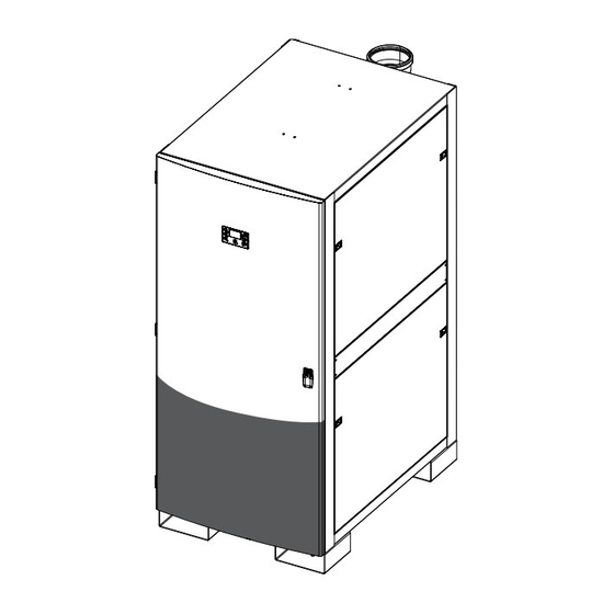
Smart. Efficient. Endless
Operation and
Installation
Manual
Model: iQ751
iQ1001
This product complies with ANSIZ21.10.3
(2011) / CSA 4.3 Gas Water Heater. For use as
a potable water heater.
Certified to
NSF/ANSI 372
WARNING
If the information in these instructions is not followed
exactly, a fire or explosion could result causing
property damage, personal injury, or death.
— Do not store or use gasoline or other flammable
vapors and liquids in the vicinity of this or any
other appliance.
WHAT TO DO IF YOU SMELL GAS
Do not try to light any appliance.
•
Do not touch any electrical switch; do not use
•
any phone in your building.
Immediately call your gas supplier from a
•
neighbor's phone. Follow the gas supplier's
instructions.
If you cannot reach your gas supplier, call the
•
fire department.
— Installation and service must be performed by
a qualified installer, service agency, or the gas
supplier.
AVERTISSEMENT
Assurez-vous de bien suivre les instructions données
dans cette notice pour réduire au minimum le
risque d'incendie ou d'explosion ou pour éviter tout
dommage matériel, toute blessure ou la mort.
— Ne pas entreposer ni utiliser d'essence ou
ni d'autres vapeurs ou liquides inflammables
à proximité de cet appareil ou de tout autre
appareil.
QUE FAIRE SI VOUS SENTEZ UNE ODEUR DE GAZ
•
Ne pas tenter d'allumer d'appareil.
•
Ne touchez à aucun interrupteur; ne pas vous
servir
des
téléphones
se
trouvant
le bâtiment.
Appelez immédiatement votre fournisseur de gaz
•
depuis un voisin. Suivez les instructions
du fournisseur.
Si vous ne pouvez rejoindre le fournisseur,
•
appelez le service des incendies.
— L'installation et l'entretien doivent être assurés
par un installateur ou un service d'entretien
qualifié ou par le fournisseur de gaz.
To avoid product damage, personal injury, or
even possible death, carefully read, understand,
and follow all the instructions in the Installation
and Operation manuals before installing this
product. Improper installation, adjustment, alteration, or
maintenance can cause injury, loss of life, and/or property
damage. This water heater should be installed and
serviced by a qualified technician. The lack of proper
service can result in a dangerous condition.
dans
This manual contains safety information, installation
instructions, and maintenance procedures. It must be left
with the homeowner or placed near the water heater in
a noncombustible place. The customer should retain this
manual for future reference.
Advertisement
Table of Contents

Related Manuals for Intellihot iQ1001


Summary of Contents for Intellihot iQ1001
- Page 1 Smart. Efficient. Endless Operation and Installation Manual Model: iQ751 iQ1001 This product complies with ANSIZ21.10.3 (2011) / CSA 4.3 Gas Water Heater. For use as a potable water heater. Certified to NSF/ANSI 372 To avoid product damage, personal injury, or...
-
Page 3: Table Of Contents
6. Venting and Materials 16.3 iQ751 / iQ1001 Complete System ....64 Venting Guidelines ......20 Exhaust Vent Materials . -
Page 4: General Information
Each heat exchanger module has its own ASME certification plate located on the heat exchanger itself. A rating plate below the ASME certification plates has the serial number for the unit. Please provide this serial number for service or warranty. XX-XXXXX iQ751 - iQ1001 General Information... -
Page 5: Safety
2. Safety DANGER Safety Signal Words A. This water heater does not have a pilot. It is equipped DANGER with an ignition device which automatically lights the burner. Do not try to light the burner manually. Indicates an imminently hazardous situation which, if not avoided, will result in death or serious injury. - Page 6 CAUTION Make sure you know the location of the gas shut-off valve and how to operate it. Immediately close the gas shut-off valve if the water heater is subjected to fire, overheating, flood, physical damage, or any other damaging condition that might affect the operation of the unit.
-
Page 7: Technical Specifications
Hot Water Capacity, 140F Rise 10.1 13.4 Warranty Heat Exchanger coil – 6 years, All Other Parts – 1 year Note: Due to Intellihot's Policy of continuous product improvements, design and technical specifications are subject to change without notice iQ751 - iQ1001Technical Data... -
Page 8: Clearance Requirements
24” (61 cm) Front 2” (5.1 cm) 2” (5.1 cm) 32” (81 cm) Bottom 0” (0 mm) 0” (0 mm) 0” (0 mm) Service clearances are suggested dimensions to allow for normal service of the unit. iQ751 - iQ1001 Technical Data... -
Page 9: Dip Switch Locations And Settings
Cascade Termination DIP Switch 3 Setting (Multiple Units) Model Board 1 Board 2 Board 3 Board 4 Board 5 Board 6 iQ751 Unit 1 iQ751 Unit 2 or last unit iQ1001 Unit 1 iQ1001 Unit 2 or last unit iQ751 - iQ1001 Technical Data... -
Page 10: Overall Dimensions
Overall Dimensions iQ751/iQ1001 iQ751 - iQ1001 Technical Data... - Page 11 - iQ1001 Technical Data...
-
Page 12: Configuration Options
N/O - TANKLESS DESIGN HOT OUTLET SHUT OFF COLD SUPPLY TO INTELLIHOT HOT SUPPLY MAIN GAS SHUT OFF 1-1/4” 1-1/4” 1-1/4” 2” 2” 2” 2” 2” 2” Multiple unit system with mixing valve but no storage tank. iQ751 - iQ1001 Technical Data... - Page 13 MAIN GAS SHUT OFF TANK OUTLET 1-1/4” 1-1/4” 1-1/4” 1-1/4” SHUT OFF 2” 2” 2” 2” 2” 2” 2” 2” RECIRCULATION TANK ISOLATION LINE SHUT OFF VALVES UNIONS Multiple unit system with mixing valve and storage tank. iQ751 - iQ1001 Technical Data...
-
Page 14: Preparation Before Installation
The fresh air inlet vent must be located at least 12” from the exhaust vent. c. Contaminated or dirty air drawn into the intake pipe can damage the water heater. The warranty does not cover damage caused by airborne contaminants. iQ751 - iQ1001 Preparation Before Installation... -
Page 15: Gas Connection
For example, a gas pressure regulator connected to or walls and by the water heater itself. an iQ1001 should have a modulation range of 30,000 4. Make sure the supply line (diameter) is correctly sized for BTU/h to 1,001,000 BTU/h. In the case of multiple units it is the maximum output of the water heater(s) being installed. -
Page 16: Connecting The Gas Line
1. Install a 4-5/8” OD flanged steel coupling and gasket with a short piece of 1-1/4” NPT black pipe. To Unit To Unit iQ751 - iQ1001 Gas Connection... -
Page 17: Venting Of Gas Supply Regulators
EXCEED 14.0” W.C. on the inlet side of the water heater at any time. NOTICE Do not fire (operate) the water heater until all connections have been completed and the heat exchanger is filled with water. iQ751 - iQ1001 Gas Connection... -
Page 18: Gas Pipe Sizing Tables
Note: For 1/2” line BTU/h capacities are based on specific gravity of 0.6, pressure drop of 4.6” WC and 5.0” WC. For all other line sizes, capacities are based on specific gravity of 0.6, pressure drop of 3.0” WC iQ751 - iQ1001 Gas Connection... -
Page 19: Gas Pressure Regulator
10.5 feet for nominal pipe sizes of up to 4” 6. Each 45° elbow is equivalent to approximately: 2 feet for nominal pipe sizes of up to 1-1/2” 5 feet for nominal pipe sizes of up to 4” iQ751 - iQ1001 Gas Connection... -
Page 20: Venting And Materials
Both the iQ751 and the iQ1001 come factory installed with • Do not operate the unit in an area that is or will be under 6 inch polypropylene (PP) venting. A polypropylene to PVC construction or renovation. -
Page 21: Combustion Air Requirements
The following diagrams represent some typical direct venting configurations and are included to assist in designing the vent system. Possible configurations are not limited to the following diagrams. MAKE UP AIR MAKE UP AIR iQ751 - iQ1001 Venting and Materials... - Page 22 UP AIR Combustion Air Through Ducts Combustion Air from Interior Space 2 Openings through Horizontal Duct 2 Direct Openings or through Vertical Duct 1 sq. in. per 2000 btu/h 1 sq. in. per 1000 btu/h iQ751 - iQ1001 Venting and Materials...
- Page 23 Possible configurations are not limited to these designs. MAKE UP AIR MAKE UP AIR MAKE MAKE UP AIR UP AIR MAKE UP AIR iQ751 - iQ1001 Venting and Materials...
-
Page 24: Venting Termination
18 and 36 inches or greater than 72 inches. Multiple units. Note A: The distance between any exhaust outlet and air intake should be between 18 and 36 inches or greater than 72 inches. iQ751 - iQ1001 Venting and Materials... - Page 25 Multiple concentric units. Note A: The distance between any exhaust outlet and air intake should be between 18 and 36 inches or greater than 72 inches. IQ-023 Intake Air Exhaust Concentric Venting System Through the Roof. iQ751 - iQ1001 Venting and Materials...
-
Page 26: Venting Clearance Specifications
*Per local/gas supplier codes. Use clearances in accordance with local building codes and local gas supplier. ** For single vent pipe/direct 4 feet (1.2 m) below or to the side of opening and 1 foot above opening. In accordance with Z223.1 In accordance with CSA B149.1 iQ751 - iQ1001 Venting and Materials... -
Page 27: Common Venting For Multiple Units
A vent system’s length shall not exceed the maximum length outlined in the chart below: Maximum Vent Length (in ft.) for Various Venting Designs for iQ751 and iQ1001 Duct Size and Model Number Venting 6”... - Page 28 Do not transition into a reducer or use a t-fi tting. Transitions should always be directed into a straight run of pipe. Do not use 90 degree transition into a reducer or a straight pipe. iQ751 - iQ1001 Venting and Materials...
- Page 29 The following diagrams represent some typical direct venting configurations and are included to assist in designing the vent system. Possible configurations are not limited to the following diagrams. MAKE UP AIR MAKE UP AIR MAKE UP AIR iQ751 - iQ1001 Venting and Materials...
- Page 30 “Vent Diameter Sizing and Lengths” on page 27. MAKE UP AIR MAKE UP AIR MAKE UP AIR MAKE UP AIR MAKE UP AIR MAKE UP AIR DECOMMISSIONED AIR INTAKE AND EXHAUST iQ751 - iQ1001 Venting and Materials...
-
Page 31: Combustion (Fresh) Air Inlet Exhaust Outlet Con
On multiple unit installations, the piping from the water heater must be connected into the properly-sized piping. Use the table in the Specification section to determine the diameter of the common connecting piping between each individual water heater. iQ751 - iQ1001 Venting and Materials... - Page 32 In that case, you must use Schedule 80 CPVC or Approved Polypropylene in the USA or Type BH Special Gas Vent Class IIB (CPCV) or Class IC (Polypropylene) that conforms to ULC-S636 in Canada. iQ751 - iQ1001 Venting and Materials...
-
Page 33: Water Connections
2. Install a tee fitting with either a pressure relief valve or a Manganese 0.05 mg/l temperature and pressure relief valve, as required by your local code. 6.5-8.5 mg/l Sulfate 205 mg/l Total Dissolved Solids (TDS) 500 mg/l Zinc 205 mg/l iQ751 - iQ1001 Water Connections... - Page 34 BTU/HR rating into the 3/4” female NPT port on the back of the unit. Note: The water heater is designed with an internal high temperature shut-off switch and, therefore, only a pressure relief valve is required for these units. iQ751 - iQ1001 Water Connections...
-
Page 35: Cold Water Connection
5. Leak test the water lines. Repair any leaks immediately. Condensate Line Installation 7.5.1 Connection Recommendations Due to its efficient design, the Intellihot water heater produces condensate (water) as a normal by-product of heating the water. 1. This condensate is acidic, with a pH level between 3 and 4. - Page 36 2. If required, install an inline neutralizer to treat the acidic condensate. Follow all the installation instructions included with the neutralizer. Inline Neutralizer iQ751 - iQ1001 Water Connections...
-
Page 37: Electrical Power
Wiring Diagram section in this manual for additional information. NOTICE The electrical connections for the water heaters are polarity sensitive. Before connecting the water heater to the power source, test the polarity of the electrical circuit. iQ751 - iQ1001 Electrical... - Page 38 Units section of the manual for additional information. Note: If multiple units are being installed, the gauge of wire to the junction box must be increased to meet the additional electrical load. Consult the electrical codes for the correct wire size. iQ751 - iQ1001 Electrical...
-
Page 39: Propane (Lpg) Conversion
PROPANE Refer to Adjusting the CO Level section in this manual for DIP Switch Settings (Réglages des commutateurs DIP) instructions on connecting a calibrated CO analyzer to the gas valve. Natural Gas Propane (Gaz naturel) iQ751 - iQ1001 Propane Conversion... -
Page 40: Adjusting Co Level
NG - 8” W.C. LP - 11” W.C. The service technician must confirm Static gas pressures before setting High Fire and Low Fire CO and CO values. iQ751 - iQ1001 Adjusting CO2 Level... - Page 41 12. Press the Down arrow key to let the unit fire at low fire. 13. Record values in table column 3, ‘Lo’. If the CO values are within the 8.6%-8.9% range, proceed to Step 15, otherwise continue with Step 14. iQ751 - iQ1001 Adjusting CO2 Level...
- Page 42 Screen. 17. Repeat steps 9-15 until all the modules are set to the desired CO levels. H1, H2 and H3 for the iQ751. H1, H2, H3, and H4 for the iQ1001. iQ751 - iQ1001 Adjusting CO2 Level...
-
Page 43: Operation
R) Indicates the level of energy usage. There are four “bar” indicators and each represent 25% of gas usage. S) Indicates outlet water temperature. T) Indicates multiple units are daisy chained and programed. When flashing, indicates an error in communication iQ751 - iQ1001 Operation... -
Page 44: Turning Water Heater On And Off
5. Press and release the Time button again. 1. Press and release the Time button. The colon (:) between the hours and minutes should now The minute section of the time display will flash. be flashing, indicating the time has been properly set. iQ751 - iQ1001 Operation... -
Page 45: Adjusting The Water Temperature
Release the Orange button to return to the home screen. Once the desired temperature is selected, the unit will heat water up to that temperature. When the Orange button is released, the Home screen will appear. iQ751 - iQ1001 Operation... -
Page 46: Error Screen
Press and release the ENTER button to view the parameters for the next heat exchanger. After the last heat exchanger (H4 for iQ1001, H3 for iQ751) is shown, press ENTER to return 11.9 Heat Exchanger Parameters to the main screen. -
Page 47: Initial Startup
Also check the electrical panel circuit breaker and reset it if necessary. If the circuit breaker trips again, do not reset. Hot Water Disconnect the plug and have a qualified technician diagnose the Valve problem. Cold Water Valve Valve iQ751 - iQ1001 Initial Startup... -
Page 48: Programming
Note: If the Enter button is not pressed within 30 seconds of 2. Follow the instructions in the specific section to enter the inactivity, the display will return to the home screen. desired settings. iQ751 - iQ1001 Programming... - Page 49 Performance History Codes. Example of water heater module H4 with an E3 Blocked Flue error code. This is the oldest recorded (number 10). After the codes are displayed, the display will go back to the main screen. iQ751 - iQ1001 Programming...
- Page 50 Press and hold the Enter button for three seconds to save the settings and return to the home screen. Note: If the Enter button is not pressed within 30 seconds of inactivity, the display will return to the home screen. iQ751 - iQ1001 Programming...
- Page 51 Press the Enter button to save the changes and return to the main display. Note: If the Enter button is not pressed within 30 seconds of inactivity, the display will return to the home screen. iQ751 - iQ1001 Programming...
- Page 52 #2 is being replaced, then the replacement controller should be set with an ID of “H2”. Press and hold the Enter button for three seconds to save the setting and return to the home screen. iQ751 - iQ1001 Programming...
-
Page 53: Multiple Units
9. If necessary, press the Power button to turn OFF each to trip while the other units can continue to operate. water heater in the system. 10. Disconnect power from all the units in the system. iQ751 - iQ1001 Multiple Units... - Page 54 11. Open the front cover and locate the main circuit boards. iQ1001 Shown (Four Circuit Boards). iQ751 Has Only Three Circuit Boards. 12. Connect a communication cable from the upper port on circuit board 3 (iQ751) or 4 (iQ1001) of the first water heater to the upper port of circuit board 1 of the second water heater.
- Page 55 OFF position (right). There are two additional switches on Model iQ751 and three additional switches on Model iQ1001. 15. On any water heater unit between the fi rst and last unit, Unit 2 and/or Unit 3, position all DIP SW3 switches in the OFF position (left).
-
Page 56: Dip Switch Configuration Drawings
14.3 DIP Switch Configuration Drawings Unit 1 Unit 2 Unit 3 Unit 4 iQ751 Unit 1 Unit 2 Unit 3 Unit 4 iQ1001 iQ751 - iQ1001 Multiple Units... -
Page 57: Maintenance
Continue to rinse the filter until all traces of cleaner are gone. It may be necessary to repeat Steps 1 and 2 3. After inspection and/or cleaning, replace the air filter and snugly tighten the band clamp. iQ751 - iQ1001 Maintenance Section... -
Page 58: Condensate Sediment Cup Cleaning
1. Twist the bottom of the sediment cup to release the locking clips. 15.2 Condensate Sediment Cup Cleaning There are four (iQ751) and five (iQ1001) sediment cups located inside the water heater cabinet. These cups should be removed and cleaned annually. -
Page 59: Maintenance-Free Circulation Pump
Whenever making a setting for a specific water heater heat exchanger, use the following diagram to identify which control board controls which heat exchanger module. The control boards and heat exchanger modules should also have corresponding numbers attached to them. iQ751 - iQ1001 Maintenance Section... -
Page 60: Troubleshooting
50°F, 10 Kohm at 77°F, 3 Kohm at 140°F) • OUt - heat exchanger water outet temperature sensor. • FL - Flue temperature sensor. • IN - inlet water temperature sensor. • Replace controller • Faulty Controller iQ751 - iQ1001 Troubleshooting Section... - Page 61 • Ensure dip switch (SW3) is ON in first and last units and OFF in all other units • Ensure each unit numbering is unique under the dC mode iQ751 - iQ1001 Troubleshooting Section...
- Page 62 Modulate Burner To Maintain Temperature De-energize Ignition Post Purge IH-56 750 iQ751 - iQ1001 Troubleshooting Section...
-
Page 63: Iq751 / Iq1001 Individual Module
16.2 iQ751 / iQ1001 Individual Module iQ751 - iQ1001 Troubleshooting Section... -
Page 64: Iq751 / Iq1001 Complete System
16.3 iQ751 / iQ1001 Complete System iQ751 - iQ1001 Troubleshooting Section... - Page 65 NOTES...
- Page 66 This warranty is limited to repairs or replacement of parts, Manganese 0.05 mg/l at Intellihot’s option that are proven to be defective under Odor 3 threshold odor number normal use and connected only to potable water systems.
-
Page 67: Warranty
1-year period from the eff ective date. Intellihot shall not be liable for indirect, special, incidental, consequential, or other similar damages, including lost profi ts, arising from or relating to the unit. -
Page 68: Requirements For State Of Massachusetts
13. Requirements for State of Massachusetts Notice Before Installation 3. SIGNAGE. A metal or plastic identification plate shall be permanently This appliance must be installed by a licensed plumber or gas mounted to the exterior of the building at a minimum fitter in accordance with the Massachusetts Plumbing and height of eight (8) feet above grade directly in line with Fuel Gas Code 248 CMR Sections 2.00 and 5.00. -
Page 69: Product Warranty Card
9. Product Warranty Card To activate your warranty, please fill out the information in the form below and mail to the following address: Warranty Registration Intellihot Green Technologies, Inc. 2900 W. Main Street Galesburg, IL 61401 Model: __________________ Serial Numbers (up to 4):... - Page 72 Dealer / Installer Contact Information: IGT-MNL0006 (12/2014) Printed in the USA...
Need help?
Do you have a question about the iQ1001 and is the answer not in the manual?
Questions and answers