Table of Contents

Advertisement

WARNING
If the information in these instructions is not followed
exactly, a
re or explosion could result causing
property damage, personal injury, or death.
— Do not store or use gasoline or other ammable
vapors and liquids in the vicinity of this or any
other appliance.
WHAT TO DO IF YOU SMELL GAS
Do not try to light any appliance.
Do not touch any electrical switch; do not use
any phone in your building.
Immediately call your gas supplier from a
neighbor's phone. Follow the gas supplier's
instructions.
If you cannot reach your gas supplier, call the
re department.
— Installation and service must be performed by
a quali ed installer, service agency, or the gas
supplier.
AVERTISSEMENT
Assurez-vous de bien suivre les instructions données
dans cette notice pour réduire au minimum le
risque d'incendie ou d'explosion ou pour éviter tout
dommage matériel, toute blessure ou la mort.
— Ne pas entreposer ni utiliser d'essence ou
ni d'autres vapeurs ou liquides in ammables
à proximité de cet appareil ou de tout autre
appareil.
QUE FAIRE SI VOUS SENTEZ UNE ODEUR DE GAZ
Ne pas tenter d'allumer d'appareil.
Ne touchez à aucun interrupteur; ne pas vous
servir
des
téléphones
se
trouvant
dans
le bâtiment.
Appelez immédiatement votre fournisseur de gaz
depuis un voisin. Suivez les instructions
du fournisseur.
Si vous ne pouvez rejoindre le fournisseur,
appelez le service des incendies.
— L'installation et l'entretien doivent être assurés
par un installateur ou un service d'entretien
quali é ou par le fournisseur de gaz.
Operation & Installation Manual
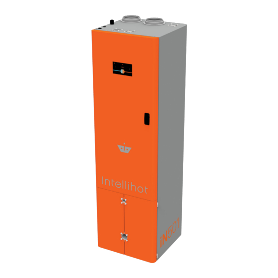
iN401
iN501

Advertisement

Table of Contents
loading
Need help?

Need help?

Do you have a question about the iN401 and is the answer not in the manual?

Questions and answers

Summary of Contents for Intellihot iN401

  • Page 1 — Installation and service must be performed by — L’installation et l’entretien doivent être assurés a quali ed installer, service agency, or the gas par un installateur ou un service d’entretien quali é ou par le fournisseur de gaz. supplier. Operation & Installation Manual iN401 iN501...
  • Page 2 Thank you for purchasing this Intellihot unit. This unit is designed for years of trouble free operation, and I urge you to read and follow the instructions in this “Operation & Installation Manual.” Our mission to create a better heating system began back in the winter of 2005 when a tank water heater broke down and flooded my basement.
  • Page 3: Table Of Contents

    Table of Contents 1. General Information 8. Water Connections Items Shipped With Water Heater..2 8.1 Quick Reference Installation Instructions . . . 28 Serial Number Locations ....2 8.2 Hot Water Connection .
  • Page 5 The lack of proper service can result in a dangerous condition. Due to Intellihot’s policy of continuous product improvement and technology, the design and/or technical specifications in this manual are subject to change without notice.
  • Page 6: General Information

    Temperature and Pressure Relief Valve (must be installed) Unit Serial Number: ______________________________ Heat Engine 1 (ASME) Serial Number: _____________ Heat Engine 2 (ASME) Serial Number: _____________ Communication Date of Installation: ___ / ___ / ______ Cable Keys Operator Manual iN401 - iN501 General Information May 2019 - Revision 00...
  • Page 7: Safety

    Designed for operations at outlet temperature(s) not in the vent terminations. Regularly inspect the exhaust excess of 190°F (88°C). vent pipe and the air intake pipe to ensure they remain clear from obstructions at all times. iN401 - iN501 Safety May 2019 - Revision 00...
  • Page 8 The appliance should be located in an area where leakage within the unit or at its connections will not result in damage to the surrounding area. The manufacturer will not be responsible for any damage resulting from leaking if adequate drainage is not provided. iN401 - iN501 Safety May 2019 - Revision 00...
  • Page 9: Technical Specifications

    Hot Water Output (140°F Rise) Warranty Heat Engine Coil – 10 years, All Other Parts – 2 years Note: Due to continuous product improvements, the design and technical specifications are subject to change without notice. iN401 - iN501 Technical Specifications May 2019 - Revision 00...
  • Page 10: Nomenclature

    2” (5 cm) 2” (5 cm) 12” (31 cm) Bottom 0” (0 mm) 0” (0 mm) 0” (0 mm) Service clearances are required dimensions to allow for normal service of the unit. Drain Hose iN401 - iN501 Technical Specifications May 2019 - Revision 00...
  • Page 11: Connection Specifications

    High Fire 9.1% to 9.3% < 200 ppm Low Fire 9.1% to 9.3% < 60 ppm Propane Gas High Fire 10.1% to 10.5% < 200 ppm Low Fire 10.1% to 10.5% < 60 ppm iN401 - iN501 Technical Specifications May 2019 - Revision 00...
  • Page 12: Overall Dimensions

    50,80 [2.00] [2.00] 160,34 [6.31] 134,25 3,99 254,00 25,00 [5.29] 3/4" PVC CONDENSATE DRAIN [0.16] [10.00] [0.98] FRONT SIDE REAR 54,36 262,50 [2.14] [10.33] 102,45 [4.03] 151,55 [5.97] 303,11 [11.93] 3X ?15,88 [0.63] BOTTOM iN401 - iN501 Technical Specifications May 2019 - Revision 00...
  • Page 13: Configuration Options

    Check Valve Pipe Coupling Pipe Cap Recirculation Pump Cold Water Supply Gas Supply Supply Expansion Tank Traditional Tank-Type Heater Hot Water Return Recirculation Line Multiple unit system with mixing valve but no storage tank. iN401 - iN501 Technical Specifications May 2019 - Revision 00...
  • Page 14 Isolation Valve Check Valve Pipe Coupling Pipe Cap Recirculation Pump Hot Water Supply Cold Water Supply Gas Supply Expansion Tank Hot Water Return Recirculation Line Multiple unit system with mixing valve but no storage tank. iN401 - iN501 Technical Specifications May 2019 - Revision 00...
  • Page 15: Quick Reference Installation Guide

    9. If connecting multiple units together, refer to “13. Connecting Multiple Units” on page 48. 10. Fill out the Warranty Card and return it to Intellihot. For a copy of the card go to “18. Product Warranty” on page iN401 - iN501 Quick Reference Installation Guide...
  • Page 16 4. If multiple units are being installed, follow these instructions for each unit. iN401 - iN501 Quick Reference Installation Guide May 2019 - Revision 00...
  • Page 17: Preparation Before Installation

    The warranty does not cover damage caused by airborne contaminants. If the incoming water is known to have a high mineral content or “hardness” (see warranty section), treatment is recommended upstream from the water heater. iN401 - iN501 Preparation Before Installation May 2019 - Revision 00...
  • Page 18: Gas Connection

    2. The gas pressure regulator must have the same or higher minimum to maximum modulation range as the model it is regulating. For example, an iN401 gas pressure regulator should have a modulation range of 30,000 BTU/h to 399,999 BTU/h.
  • Page 19: Venting Of Gas Supply Regulators

    4. The gas pipe must not be supported by the drip leg. 3. Assembled piping should be clean of all scale, debris, 5. Following local building codes when selecting and installing metal particles, or foreign material. a shut-off valve. iN401 - iN501 Gas Connection May 2019 - Revision 00...
  • Page 20: Connecting Gas Line To Unit

    Do not fire (operate) the water heater until all connections have been completed and the heat engine is filled with water. 1. Install a 4-5/8” OD flanged steel coupling and gasket with a short piece of 1-1/4” NPT black pipe. iN401 - iN501 Gas Connection May 2019 - Revision 00...
  • Page 21: Gas Pipe Sizing Tables

    Note: For 1/2” line BTU/h capacities are based on specific gravity of 0.6, pressure drop of 4.6” WC and 5.0” WC. For all other line sizes, capacities are based on specific gravity of 0.6, pressure drop of 3.0” WC iN401 - iN501 Gas Connection May 2019 - Revision 00...
  • Page 22 1,950,000 3,110,000 5,500,000 11,200,000 292,000 600,000 899,000 1,730,000 2,760,000 4,880,000 9,950,000 265,000 543,000 814,000 1,570,000 2,500,000 4,420,000 9,010,000 Note: The line BTU/h capacities are based on specific gravity of 1.5, pressure drop of 0.5” WC. iN401 - iN501 Gas Connection May 2019 - Revision 00...
  • Page 23: Air Intake Inlet And Exhaust Gas Outlet Pipe Connections

    “7.3.3 Side Wall Air Intake Inlet and Exhaust Gas Outlet Pipe Termination” on page 21. “7.3.4 Roof Air Intake Inlet and Exhaust Gas Outlet Pipe Termination” on page 22. iN401 - iN501 Air Intake Inlet and Exhaust Gas Outlet Pipe Connections May 2019 - Revision 00...
  • Page 24: Two Pipe Vent System (Direct Vent)

    Do not connect any other appliance vents to the water heater inlet or outlet pipes. 6. If multiple units are installed, make sure the diameter of the connecting exhaust gas outlet pipe is properly sized for the number of units being installed. iN401 - iN501 Air Intake Inlet and Exhaust Gas Outlet Pipe Connections May 2019 - Revision 00...
  • Page 25: Multiple Unit Configurations

    72 inches apart or more. 3. To avoid moisture and frost build-up to openings on adjacent homes, use 45° elbows, 90° elbows, or tees for the vent termination to direct the exhaust gas fumes away from the building. Intake iN401 - iN501 Air Intake Inlet and Exhaust Gas Outlet Pipe Connections May 2019 - Revision 00...
  • Page 26: Roof Air Intake Inlet And Exhaust Gas Outlet Pipe Termination

    18 and 36 Intake inches apart. If this minimum specification cannot be met, the air intake inlet and exhaust gas outlet pipes should be 72 inches apart or more. Intake iN401 - iN501 Air Intake Inlet and Exhaust Gas Outlet Pipe Connections May 2019 - Revision 00...
  • Page 27: Multiple Units

    “13. Connecting Multiple Units” on page 48 Exhaust Intake Intake Exhaust Intake Intake Intake Exhaust Intake Decommisioined Air Intake and Gas Exhaust iN401 - iN501 Air Intake Inlet and Exhaust Gas Outlet Pipe Connections May 2019 - Revision 00...
  • Page 28: Combustion Air Requirements

    **Where one opening is required, it must be located within 12 inches of the ceiling. 7.6 Intake Air Inlet and Exhaust Gas Outlet Pipe Diameter and Length The iN401 and iN501 come factory installed with 4 inch polypropylene (PP) venting. The following chart outlines the maximum length of venting allowable for each model.
  • Page 29: Venting Clearance Specifications

    Near soffit vents or crawl space vents or other areas where condensate or vapor could create a nuisance or hazard or cause property damage; or Where condensate vapor could cause damage or could be detrimental to the operation of regulators, relief valves, or other equipment. iN401 - iN501 Air Intake Inlet and Exhaust Gas Outlet Pipe Connections May 2019 - Revision 00...
  • Page 30: Exhaust Gas Outlet Pipe Materials

    CAN/CGA B149.1, as well as all applicable local codes and will turn off automatically to protect the vent pipe. Once the regulations when selecting vent pipe materials. exhaust gas temperature has dropped to a normal operating level, the unit will automatically restart. iN401 - iN501 Air Intake Inlet and Exhaust Gas Outlet Pipe Connections May 2019 - Revision 00...
  • Page 31: Recommended Exhaust Gas Outlet Pipe Transitions

    Do not use reducers in a straight run of pipe. Do not transition into a reducer or use a t-fitting. Transitions should always be directed into a straight run of pipe. Do not use 90 degree transition into a reducer or a straight pipe. iN401 - iN501 Air Intake Inlet and Exhaust Gas Outlet Pipe Connections May 2019 - Revision 00...
  • Page 32: Water Connections

    7. To conserve energy, insulate all hot water pipes and recirculation pipes. iN401 - iN501 Water Connections May 2019 - Revision 00...
  • Page 33: Cold Water Connection

    4. Connect the unit to the existing cold water pipes. 5. Connect the unit to the building’s cold water pipes. If multiple water heaters are being installed, the diameter of the main cold water pipe needs to be sized by an engineering professional. iN401 - iN501 Water Connections May 2019 - Revision 00...
  • Page 34 5. Locate the unit close to a floor drain or use a condensate pump. 6. Ensure that all connections are watertight. 7. Follow all local codes for handling exhaust gas condensate. 8. Locate the unit near an electrical outlet. iN401 - iN501 Water Connections May 2019 - Revision 00...
  • Page 35: Electrical Power

    National Electrical Code (NFPA 70) in the USA, or the CGA C22.1 Canadian Electrical Code - Part 1. For a single in401 or iN501 water heater, the circuit breaker(s) should be at least 15 amps per circuit...
  • Page 36: Adjusting Co Level

    CO and CO values. Before adjustments made, service technician must confirm the static gas pressure meets these minimum requirements. Natural Gas - 8” W.C. Propane - 11” W.C. iN401 - iN501 Adjusting CO2 Level May 2019 - Revision 00...
  • Page 37 High Fire procedure for all heat engines. 6. At at a flow rate of 6.0 GPM, Top Heat Engine will start. 7. Allow three minutes of operation at High Fire. 8. Record “initial output” in Hire Fire Recorded Values table. iN401 - iN501 Adjusting CO2 Level May 2019 - Revision 00...
  • Page 38 15. Once the desired values are achieved, record the new Low Fire CO “adjusted values” in the table. 16. From the display screen, press Bottom Heat Engine and repeat the Low Fire procedure for all heat engines. iN401 - iN501 Adjusting CO2 Level May 2019 - Revision 00...
  • Page 39: Natural Gas To Propane Conversion

    Open the front door and locate the main circuit board. Recommended Gas Pressure 11” W.C. Note: There are two control boards in the iN401/iN501. Maximum Static Gas Pressure 13” W.C. d. Locate DIP Switch 1 on each of the two circuit boards.
  • Page 40 2. Follow the display screens to check if the unit is now set to propane. 3. Refer to section “10. Adjusting CO2 Level” on page 32 in this manual for instructions to adjust CO levels. iN401 - iN501 Natural Gas to Propane Conversion May 2019 - Revision 00...
  • Page 41: Operation

    Turning the unit OFF does not disconnect it from the power source. Whenever working around electrical components within the water heater, turn off the power at its source. Touching live electrical components can cause serious injury or death. iN401 - iN501 Operation May 2019 - Revision 00...
  • Page 42: Setting The Time

    1. Firmly press the (+) and (–) to increase or decrease the temperature by 5°F. Firmly hold the icon until the display reaches the desired temperature. Press the Up/Down arrows to make adjustments. Press the Back button to return to the main screen. iN401 - iN501 Operation May 2019 - Revision 00...
  • Page 43: Security

    It is not necessary to set a passcode for the water heater to function properly. This feature is available to help prevent unauthorized access to the unit. If a passcode is set, it must be entered prior to accessing the main screen. iN401 - iN501 Operation May 2019 - Revision 00...
  • Page 44: Changing Passcode

    12.5.2 Changing Passcode iN401 - iN501 Operation May 2019 - Revision 00...
  • Page 45: Forgot Passcode

    12.7 Temp / Flow 12.5.3 Forgot Passcode Provides the general operating parameters of each heat If the unit passcode is lost or forgotten, press the “?” icon engine. and call technical support. 12.6 NOT USED iN401 - iN501 Operation May 2019 - Revision 00...
  • Page 46: Life Screen

    Service Required: Take IMMEDIATE action when this screen appears Press the (+) button to show the details of the various heat engines. because the part life is critical. To reset life, press and hold the appropriate bar and follow the prompts. iN401 - iN501 Operation May 2019 - Revision 00...
  • Page 47: Unit Information

    This screen provides the model, software version, serial the part being replaced. number, and a link to the contact us screen for the water heater. iN401 - iN501 Operation May 2019 - Revision 00...
  • Page 48: More Screens

    12.10 More Screens 12.10.2 Error History 12.10.1 Cellular Intellihot Gen II water heaters are cellular capable. This feature also allows the units to be monitored and controlled from a mobile device. There are two error history screens. One screen provides an overview of the entire unit.
  • Page 49: Tellicare Service (Subscribe At Startup)

    3. If the unit is unable to find a connection, this screen appears. 1. Tap anywhere on the screen to continue. 4. If the unit is able to find a connection, the following screens appear. iN401 - iN501 Operation May 2019 - Revision 00...
  • Page 50 5. If for some reason the setup is not completed, the following screen appears: 6. Note: Each individual unit must be registered and each unit can only be registered once. iN401 - iN501 Operation May 2019 - Revision 00...
  • Page 51 7. Once the service is set up, various status screens provide the expiration date of the service and if it is on an auto renewal schedule. iN401 - iN501 Operation May 2019 - Revision 00...
  • Page 52: Connecting Multiple Units

    9. If necessary, press the Power button to turn OFF each page 28 for additional information. water heater in the system and disconnect power from all the units in the system. 7. Do Not connect communication cables at this time. iN401 - iN501 Connecting Multiple Units May 2019 - Revision 00...
  • Page 53: Tellicare For Multiple Units

    Remove the attached cable at each end from the referenced jacks and set aside. iN401/iN501 have 2 Circuit Boards. 11. Connect the included communication cable from an open jack on the circuit board in one unit to an open jack in the next unit.
  • Page 54: Maintenance

    1. Twist the bottom of the sediment cup to release the 14.2 Heat Engine Locations locking clips. Use the following diagrams to identify the location of the heat engines. iN401 - iN501 Maintenance May 2019 - Revision 00...
  • Page 55 4. Remove any dirt and debris build-up using soap and warm water. 5. Replace the inner sediment cup and reattach the entire unit. Date Last Serviced Month Year iN401 - iN501 Maintenance May 2019 - Revision 00...
  • Page 56: Wiring Diagrams And Troubleshooting

    15. Wiring Diagrams and Troubleshooting 15.1 Operational Flow Chart Is Temp. Within Limits Is Temp. Within Limits IH-56 iN401 - iN501 Wiring Diagrams and Troubleshooting May 2019 - Revision 00...
  • Page 57: Complete Wiring Diagram (All Models)

    15.2 Complete Wiring Diagram (all models) iN401 - iN501 Wiring Diagrams and Troubleshooting May 2019 - Revision 00...
  • Page 58 BK-LINE FUSE* INTELLIHOT WATER HEATER FUSE* WIRING DIAGRAM: iN401 / iN501 PUMP *125V, 5A LOAD BK WT GN SLOW-BLOW WIRE COLOR CODE BLACK BLUE POWER BROWN SWITCH GREEN WHITE GN/YL GREEN/YELLOW LINE iN401 - iN501 Wiring Diagrams and Troubleshooting May 2019 - Revision 00...
  • Page 59: Control Board Wiring Diagram

    • Faulty sensor. • Measure resistance of sensor at connector (18 kΩ at 50°F, 10 kΩ at 77°F, 3 kΩ at 140°F). • Faulty controller. • Replace controller. iN401 - iN501 Wiring Diagrams and Troubleshooting May 2019 - Revision 00...
  • Page 60 • Ensure that the communication cable is not bundled or tied to any high voltage lines. • Ensure dip switch (SW3) is ON in first and last units and OFF in all other units. • Ensure each unit numbering is unique. iN401 - iN501 Wiring Diagrams and Troubleshooting May 2019 - Revision 00...
  • Page 61 • Replace fuse (5 Amp) • Pump fuse blown. • Replace pump. • Faulty pump. • Replace controller. • Faulty controller. Fuel Type • Wrong fuel type being used. •Use correct fuel type. iN401 - iN501 Wiring Diagrams and Troubleshooting May 2019 - Revision 00...
  • Page 62 • A system alert or fault is present • Press the Menu bar and refer to the remedy for indicated (main menu screen). part or system. • Malfunction of monitored part or system. iN401 - iN501 Wiring Diagrams and Troubleshooting May 2019 - Revision 00...
  • Page 63 • A system alert or fault is present • Press the Menu bar and refer to the remedy for indicated (main menu screen). part or system. • Malfunction of monitored part or system. iN401 - iN501 Wiring Diagrams and Troubleshooting May 2019 - Revision 00...
  • Page 64: Serviceable Parts

    16. Serviceable Parts 16.1. Blower & HEX Parts Part Number Description Item IGT-SPR0011 Gas Valve Kit IGT-ELC0147 Gray Swirl Plate IGT-ELC0012 Fan Adapter Plate IGT-SPR0008 Blower Kit IGT-CST0011 Outlet Casting Adapter IGT-CST0010 Inlet Casting Adapter iN401 - iN501 Serviceable Parts August 2019 - Revision 00...
  • Page 65 16.2. Burner, Electrode & Gas Valve Item Part Number Description IGT-SPR0111 Gen II V02 Burner Kit IGT-ELC0020 Gas Valve Harness IGT-SPR0011 Gas Valve Kit IGT-SPR0106 Gen II V02 Electrode Kit iN401 - iN501 Serviceable Parts August 2019 - Revision 00...
  • Page 66 16.3. HEX & Sidecast Item Part Number Description IGT-SA0511 Top Heat Exchanger IGT-SA0512 Bottom Heat Exchanger IGT-CST0029 Side Cast - Exhaust, 3" IGT-CST0035 Side Cast - Exhaust, 4" to 3" IGT-SLS0083 Side Cast Seal iN401 - iN501 Serviceable Parts August 2019 - Revision 00...
  • Page 67 Water Hammer Arrestor IGT-FTT0235-3 Water out fitting, hot side IGT-SLS0041 Flange Seal IGT-SM0558 Close-off Plate IGT-FTT0235-4 Water out fitting, T&P side IGT-LNE0063 Corrugated Water line assembly IGT-FTT0243-1 Flange Adapter fitting IGT-LNE0064 Corrugated Water line assembly iN401 - iN501 Serviceable Parts August 2019 - Revision 00...
  • Page 68 Water In Fitting, Cold Side IGT-FTT0235-1 Flange Seal IGT-SLS0041 Flange Adapter Fitting IGT-FTT0244 Bypass Valve IGT-VL0019 Corrugated line assembly IGT-LNE0064 Water in Fitting, Strainer IGT-FTT0235-2 Water Valve kit IGT-SPR0003 Close off Plate fitting IGT-SM0558 Recirculation pump IGT-SPR0075 iN401 - iN501 Serviceable Parts August 2019 - Revision 00...
  • Page 69 16.6 Gas Connections Item Part Number Description IGT-FTT0235-5 Gas-in Casting IGT-PLG0014 Gas Corrugated tube IGT-PLG0015 Gas Corrugated tube IGT-SLS0041 Flange Seal IGT-SM0560 Close Off Plate iN401 - iN501 Serviceable Parts August 2019 - Revision 00...
  • Page 70 16.7. Electronics Part Number Description Item IGT-SPR0002 Control Board IGT-SPR0005 Igniter Module (DSI) Kit IGT-ELC0007 Air Switch IGT-SPR0065 Transformer Kit IGT-ELC0138 Rocker Switch IGT-SPR0088 Large Screen Display Kit iN401 - iN501 Serviceable Parts August 2019 - Revision 00...
  • Page 71 DSI to Electrode HV Cable IGT-ELC0278 Heat Exchanger to Control board Complete Harness IGT-ELC0279 Water Valve Wiring Harness Set IGT-ELC0280 Inlet Sensor Wiring Harness IGT-ELC0281 Outlet Sensor Wiring Harness IGT-ELC0284 Bypass Valve Wiring Harness IGT-ELC0288 Display Wiring Harness iN401 - iN501 Serviceable Parts August 2019 - Revision 00...
  • Page 72: Requirements For State Of Massachusetts

    2. APPROVED CARBON MONOXIDE DETECTORS. Each carbon monoxide detector, as required in accordance with the above provisions, shall comply with NFPA 720 and be ANSI/UL 2034 listed and IAS certified. iN401 - iN501 Requirements for State of Massachusetts May 2019 - Revision 00...
  • Page 73: Warranty

    18.1 Warranty Contaminant Level General Aluminum 0.05 to 0.2 mg/l This unit is warranted by Intellihot Inc., and covers defects Chloride 250 mg/l in materials and workmanship, subject to the applicable time Color 15 color units periods and terms below. The warranty effective start date Copper 1.0 mg/l...
  • Page 74 1-year period from the date of commissioning. Intellihot shall not be liable for indirect, special, incidental, consequential, or other similar damages, including lost profits, arising from or relating to the unit.
  • Page 75: Product Warranty

    Serial Numbers (up to 4): ______________________________________________________________ ______________________________________________________________ ______________________________________________________________ ______________________________________________________________ Owner Information: Name: _______________________________________________________ Address: ______________________________________________________ City, State, Postal Code: _______________________________________ Phone Number: _______________________________________________ Dealer Information: Sold By: _____________________________________________________ Address: ______________________________________________________ City, State, Postal Code: _______________________________________ Phone Number: _______________________________________________ iN401 - iN501 Product Warranty May 2019 - Revision 00...
  • Page 76 This page has been intentionally left blank. iN401 - iN501 Product Warranty May 2019 - Revision 00...
  • Page 77 NOTES iN401 - iN501 May 2019 - Revision 00...
  • Page 78 NOTES iN401 - iN501 May 2019 - Revision 00...
  • Page 79 Endless water. Zero waste. ™...
  • Page 80 09-2019 Part#: IGT-MNL0047 Intellihot Inc. | www.intellihot.com | 2900 W. Main Street, Galesburg, IL 61401 | 877.835.1705 | support@intellihot.com...

This manual is also suitable for:

In501

Table of Contents