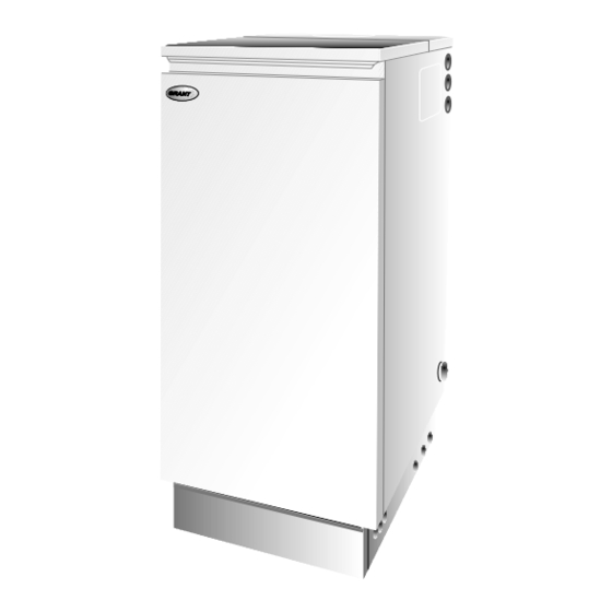
Grant EUROFLAME 50/70 User, Installation And Servicing Instructions

Grant EUROFLAME 50/70 User, Installation And Servicing Instructions

Grant euroflame kitchen/utility and boiler house models 50/70, 70/90, 90/120 and kitchen/utility system models 50/90, 90/120

Advertisement

Part No. DOC 01 Rev. 15 February 2004
USER, INSTALLATION
and
SERVICING INSTRUCTIONS
EUROFLAME
Kitchen/Utility and Boiler House Models
50/70, 70/90, 90/120 and
Kitchen/Utility System Models
50/90, 90/120
For use with Kerosene or Gas Oil
After installing the boiler leave these instructions with the User
This appliance is deemed a controlled service and specific regional statutory
requirements may be applicable

Advertisement

Table of Contents
loading

Summary of Contents for Grant EUROFLAME 50/70

  • Page 1 Part No. DOC 01 Rev. 15 February 2004 USER, INSTALLATION SERVICING INSTRUCTIONS EUROFLAME Kitchen/Utility and Boiler House Models 50/70, 70/90, 90/120 and Kitchen/Utility System Models 50/90, 90/120 For use with Kerosene or Gas Oil After installing the boiler leave these instructions with the User This appliance is deemed a controlled service and specific regional statutory requirements may be applicable...
  • Page 2: Table Of Contents

    LIST OF CONTENTS Section Subject Page User instructions ........3 Technical information ........ 6 General boiler information ......10 Boiler installation ........23 Commissioning ......... 29 Information for the user ......31 Boiler servicing ......... 31 Wiring diagrams ........34 Fault finding ..........
  • Page 3: User Instructions

    1 - USER INSTRUCTIONS About your boiler Lighting your boiler (see Fig. A or B) The boiler will provide domestic hot water and central 1 Ensure that - There is sufficient fuel, of the correct heating and is fully automatic once switched on. An type, in the supply tank and all fuel supply valves are illuminated On/Off switch, see Fig.
  • Page 4: Turning Off

    1 - USER INSTRUCTIONS Turning off your boiler (see Fig. A or B) Note: Balanced flue models (flue terminal through the wall) must only be used with Kerosene. Kitchen/Utility models for short periods - Set the On/ Do not wait until the fuel runs out before you order some Off to OFF.
  • Page 5 1 - USER INSTRUCTIONS 4 Ventilation - Always ensure that the boiler has Sealed central heating system adequate ventilation. Any ventilation openings provided by the Installer must not be obstructed. If your boiler is operating on a sealed heating system, the Periodically check that they are clear.
  • Page 6: Technical Information

    2 - BOILER TECHNICAL INFORMATION Boiler technical data 50/90 System 70/90 90/120 90/120 System Model 50/70 Water content litre * Weight (dry) 55 (bh), 76 (ku) 100 (bh), 109 (ku) 112 (bh), 121 (ku) 220 (bh), 240 (ku) 232 (bh), 252 (ku) 121 (bh), 167 (ku) (bh=Boiler House, ku=Kitchen/Utility) Max.
  • Page 7: Specifications

    2 - BOILER TECHNICAL INFORMATION Euroflame oil boilers using Class C2 kerosene Note: All boilers are despatched for use with kerosene. Net efficiency ** Model Heat Output Net Heat Input Nozzle Smoke Burner Fuel flow Flue gas press. head rate temp.
  • Page 8 2 - BOILER TECHNICAL INFORMATION Boiler dimensions See Figs. 1a and 1b Fig. 1a - 50/70 Euroflame Oil Boilers...
  • Page 9 2 - BOILER TECHNICAL INFORMATION Fig. 1b - 70/90, 50/90, 90/120 Euroflame Oil Boilers...
  • Page 10: General Boiler Information

    If required, an additional flexible fuel line (900 mm) and " to " BSP male adaptor are available from Grant Engineering (UK) Limited, for two-pipe oil supply system. All models are suitable for use with Class C2 kerosene or Class D gas oil.
  • Page 11 3 - GENERAL BOILER INFORMATION Regulations to comply with Delivery Installation of a Euroflame boiler must be in Kitchen/Utility Conventional flue models are supplied accordance with the following recommendations:- in one pack, containing the cased boiler with the burner and control panel fitted, and literature pack. a Building Regulations for England and Wales, and the Building Standards for Scotland issued by the Kitchen/Utility Balanced flue models are supplied in...
  • Page 12 " to " BSP 4 A metal bowl type filter with a replaceable male adaptor are available from Grant Engineering micronic filter must be fitted in the fuel supply line (UK) Limited). See section 3.4.6. adjacent to the boiler. A shut-off valve should be fitted before the filter, to allow the filter to be 5 The pump vacuum should not exceed 0.4 bar.
  • Page 13 3 - GENERAL BOILER INFORMATION Fig. 2 - Single pipe system Fig. 3 - Two pipe system Euroflame Oil Boilers...
  • Page 14 " to " BSP the air from the oil supply on a single pipe lift. male adaptor are available from Grant Engineering (UK) Limited). See section 3.4.6. 2 The Tiger Loop is connected close to the boiler as a two pipe system (omitting the non-return valve) as shown in Fig.
  • Page 15: Air Supply

    7 Flexible fuel lines and adaptors are available from must be carried out:- Short circuit, Polarity, Earth Grant Engineering (UK) Ltd. continuity and Resistance to earth. 8 Boiler House models - Fit the burner as described in section 4.6.
  • Page 16 3 - GENERAL BOILER INFORMATION Fig. 7 - Air supply for room sealed balanced flue boilers Minimum size of air vents required - see Figs. 7 and 8 50/70 50/90, 70/90 90/120 Vent A 113 cm² (18 in²) 145 cm² (23 in²) 194 cm²...
  • Page 17 3 - GENERAL BOILER INFORMATION Conventional flue system See Figs. 9 and 10 Grant boilers have high operating efficiencies. Care must be taken to ensure the flue system is suitable for the low flue gas temperatures. 1 An insulated flue terminating in a down draught free area, i.e.
  • Page 18 3 - GENERAL BOILER INFORMATION Connect a conventional flue To suit wall thickness (mm) Concentric low level balanced Kitchen/Utility models flue kits Rear exit Side exit 1 Lift off the two case top panels. Min. Max. Min. Max. Short Kit 50/70 Boiler House 2 Remove the insulation from the smaller panel (do not 70/90 Boiler House...
  • Page 19 Distances measured to rim of terminal. A Below a gutter or sanitary pipework * 600 Horizontal from an opening, air brick or window Clearances recommended by Grant Engineering Above ground or balcony level **300 (UK) Limited in accordance with British...
  • Page 20 3 - GENERAL BOILER INFORMATION Frost protection 3.10 For additional protection of either the entire heating 4 All water connections have been temporarily sealed system, or the boiler and localised pipework, it is with plastic caps to prevent any residual water recommended that a frost thermostat be installed.
  • Page 21 3 - GENERAL BOILER INFORMATION Fig. 11 - Kitchen/Utility system boiler water connections 3.13 Heating system diagrams See Figs. 12, 13, 14 and 15 3.13.1 Gravity domestic hot water - (See Fig. 12) Fig. 12 - Gravity domestic hot water system Euroflame Oil Boilers...
  • Page 22 3 - GENERAL BOILER INFORMATION 3.13.2 Fully pumped - (See Fig. 13) Fig. 13 - Fully pumped system 3.13.3 Kitchen/Utility sealed system - (See Fig. 14) 3 The central heating system volume, using the expansion vessel as supplied, must not exceed the 1 The boiler is suitable only for use with a sealed volume shown in section 2.1.
  • Page 23: Boiler Installation

    4 - BOILER INSTALLATION 7 Filling of the system must be carried out in a manner approved by the local Water Undertaking. Where allowed, the system may be filled via the filling loop supplied (the loop arrangement includes a double check valve assembly). 8 All fittings used in the system must be able to withstand pressures up to 3 bar.
  • Page 24 4 - BOILER INSTALLATION Model (concentric flue) Dimension (mm) Kitchen/Utility model - 50/70 Kitchen/Utility models - 70/90 and System 50/90 Kitchen/Utility model - 90/120 Boiler House model - 50/70 Boiler House model - 70/90 Boiler House model - 90/120 Fig. 16 - Concentric low level balanced flue Model Dimension (mm) A (dia)
  • Page 25 4 - BOILER INSTALLATION High level and vertical balanced flue Fitting instructions for the high level balanced flue and The equivalent flue length of each elbow is approximately vertical balanced flue are supplied with the flue kits. one metre. Only two bends should be used. Adjustable sections: The adjustable extensions are Note: The overall assembled flue length should not telescopic.
  • Page 26 4 - BOILER INSTALLATION Fit the burner 2 Check that the 'O' ring is in position (around the collar Kitchen/Utility models are supplied with the burner fitted. To fit the burner to a Boiler House of the burner combustion head). Position the burner on the boiler by sliding the combustion head into the model proceed as follows:- mounting flange on the boiler.
  • Page 27 Refer to section 8.4. For other systems not covered, static head of 10.2 metres). The charge pressure contact Grant Engineering (UK) Ltd. must not be less than the actual static head at the DO NOT connect the neutral wires to either of point of connection (see Fig.
  • Page 28 4 - BOILER INSTALLATION 3 Ensure that the flexible filling loop is fitted between 8 Check the operation of the safety valve (see Fig. the shut off valve on the mains water supply and the 20) by turning the head anticlockwise until it double check valve on the heating system.
  • Page 29: Commissioning

    5 - COMMISSIONING Refer to Figs. 21 or 22 for boiler controls Fig. 21 - Utility models It is important that the following commissioning procedure is carried out to ensure safe and efficient operation of the boiler. °C If the boiler output is to be adjusted from that which is factory, set refer to section 1.2 or 1.3 for the required settings, section 7.4 for burner head/ nozzle change instructions and Fig.
  • Page 30 5 - COMMISSIONING 7 With the burner alight, check the fuel pressure. 15 When the boiler has been adjusted and is running Refer to the Technical Information, sections 2.2 satisfactorily, balance the central heating system by and 2.3. Adjust the pressure if necessary - see Fig. adjusting the radiator lock shield valves.
  • Page 31: Information For The User

    Service Log, on page 2 of these every two years. If in doubt replace the pipes. instructions. This information may be required to validate the Grant extended warranty. Warning: Before servicing, set the boiler On/Off switch to Off (Kitchen/Utility models only), isolate the IMPORTANT electricity supply and close the fuel supply valve.
  • Page 32: Cleaning The Boiler

    7 - BOILER SERVICING 3 Remove the burner fixing nut (top of the mounting Cleaning flange) and withdraw the burner. If required, cover disconnect the flexible oil pipe(s), use a suitable container to prevent any oil spillage. Top baffle plate Note: If two flexible fuel lines are connected to the burner, identify (mark if necessary) which is the inlet and return if they are to be disconnected.
  • Page 33: Cleaning The Burner

    7 - BOILER SERVICING See table in section 2.2 or 2.3 for the correct With the combustion head removed, loosen the position. Fig. 24 shows the top baffle plate fitted electrode assembly clamp screw and slide the on the left hand side when viewed from the front of electrodes away from the nozzle.
  • Page 34: Wiring Diagrams

    8 - WIRING DIAGRAMS Kitchen/Utility boiler control panel wiring diagram Fig. 27 - Kitchen/Utility boiler System boiler control panel wiring diagram Fig. 28 - System boiler Euroflame Oil Boilers...
  • Page 35 Connector to link neutral wires (not supplied) Fig. 29- Boiler House boiler Typical control system wiring diagrams Contact Grant Engineering (UK) Limited for other systems. Kitchen/Utility model with Honeywell S Plan (HW & CH controlled by two valves) Fig. 30...
  • Page 36 8 - WIRING DIAGRAMS Boiler House model with Honeywell Y Plan (HW controlled by mid position valve) Fig. 31 System boiler with Honeywell S Plan (HW & CH controlled by two valves) Fig. 32 Euroflame Oil Boilers...
  • Page 37: Fault Finding

    8 - WIRING DIAGRAMS System boiler with Honeywell Y Plan (HW controlled by mid position valve) Fig. 33 9 - FAULT FINDING Riello RDB burner fault finding Euroflame Oil Boilers...
  • Page 38: Boiler Fault Finding

    9 - FAULT FINDING Boiler fault finding Warning: Always isolate the electricity supply to the boiler before working on the boiler. Faults Remedies Boiler will not start No fuel supply. Ensure that an adequate supply of fuel is available and that the fuel supply valve is open.
  • Page 39: Burner Spares

    10 - BURNER SPARE PARTS Riello RDB burner - exploded view 10.1 50/70 Description Riello Grant Description Riello Grant Part No. Part No. Part No. Part No. Gasket 3005787 RBS105 Needle valve 3007582 RBS109 Flange 3006384 RBS110 Regulator 3008651 RBS120...
  • Page 40: Health And Safety Information

    11 - HEALTH AND SAFETY INFORMATION Under the Consumer Protection Act 1987 and Section 6 of the Health & Safety at Work Act 1974, we are required to provide information on substances hazardous to health (COSHH Regulations 1988). Adhesives, sealants and paints used in the manufacture of the product are cured and present no known hazards when used in the manner for which they are intended.
  • Page 41: Ec Declaration Of Conformity

    12 - EC DECLARATION OF CONFORMITY We declare that the Euroflame range of Oil Boilers equipped with Riello RDB burner approved to EN 267: 1991 satisfy the requirements of the following European Directives:- 89/336/EEC - Electromagnetic Compatibility Directive Referred to the generic standards EN 55014: 1993, EN 50082: 1: 1992 73/23/EEC - Electrical Equipment Safety Regulations Directive Referred to the generic standard NO: 3260: The Electrical Equipment (Safety) Regulations: 1994 92/42/EEC - Hot Water Boiler Efficiency Directive...
  • Page 42 Euroflame Oil Boilers...
  • Page 43 Euroflame Oil Boilers...
  • Page 44 All goods sold are subject to our official Conditions of Sale, a copy of which may be obtained on application. © Grant Engineering (UK) Limited 2004. No part of this manual may be reproduced by any means without prior written consent.

Table of Contents