
Related Manuals for Grant Vortex VORTMOD1521


Summary of Contents for Grant Vortex VORTMOD1521
- Page 1 Grant Vortex Outdoor Module / External Condensing Oil Boiler Range Installation and Servicing Instructions IRL | DOC 0018 | Rev 01.00 | July 2021...
- Page 2 This manual is accurate at the date of printing but will be superseded and should be disregarded if specifi cations and/or appearances are changed in the interests of continued product improvement. However, no responsibility of any kind for any injury, death, loss, damage or delay however caused resulting from the use of this manual can be accepted by Grant Engineering (Ireland) ULC, the author or others involved in its publication.
-
Page 3: Table Of Contents
CONTENTS INTRODUCTION FLUE SYSTEM AND AIR SUPPLY How a condensing boiler operates Air supply Boiler description Plume diverter kit Flue options Conventional fl ue systems Boiler components External vertical conventional fl ue (Green System) TECHNICAL DATA External horizontal conventional fl ue Boiler technical data (Green System) Sealed system data... -
Page 4: Introduction
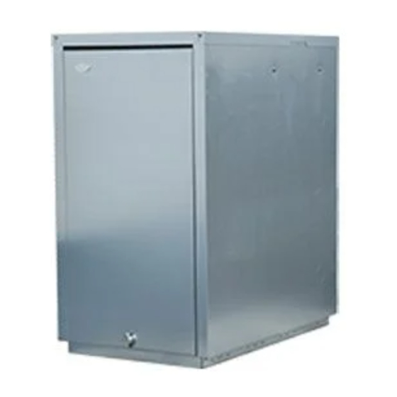
fl ue system. maximum fl ow temperature of 75°C. BOILER DESCRIPTION Conventional fl ues only may be fi tted to Grant Vortex Module boilers. Grant Vortex Module modules have an insulated weatherproof enclosure made of galvanised steel and are designed for external... -
Page 5: Boiler Components
RBS36XS) and 3/8” to 1/4” BSP male adaptor (product code: Service/Test Switch Z3003602) are available to purchase from Grant, for two-pipe oil supply systems. A service switch is fi tted to the control panel to allow the Service Engineer to test-fi... -
Page 6: Technical Data
TECHNICAL DATA BOILER TECHNICAL DATA Table 2-1: Boiler technical data Module Module Units 15/21 15/26 26/36 36/46 46/58 58/70 litre 16.5 Water content Weight (dry) Maximum heat output (Kerosene) Btu/h 71,700 88,700 122,800 157,000 197,900 238,800 Minimum fl ow rate (∆T=10°C) 1,800 2,200 3,000... -
Page 7: Burner Settings
The data given above is approximate only and is based on the boiler being used with a low level balanced fl ue. The above settings may have to be adjusted on site for the correct operation of the burner. Gas Oil is NOT suitable for use with Grant Vortex boiler range The fl ue gas temperatures given above are ± 10%. -
Page 8: Boiler Dimensions
BOILER DIMENSIONS PLAN VIEW ø ø REAR VIEW LEFT SIDE VIEW RIGHT SIDE VIEW Figure 2-1: 15/21 External module dimensions 1006 PLAN VIEW ø ø LEFT SIDE VIEW RIGHT SIDE VIEW END VIEW Figure 2-2: 15/26, 26/36 and 36/46 External module dimensions Page 8 Section 2: Technical Data... - Page 9 1157 PLAN VIEW ø ø REAR VIEW LEFT SIDE VIEW RIGHT SIDE VIEW Figure 2-3: 46/58 and 58/70 External module dimensions Section 2: Technical Data Page 9...
-
Page 10: Oil Storage And Supply System
Oil storage tanks should comply with the following standards: • ¼ʺ isolating valve (product code: ISOLATION1/4) • Plastic tanks OFT T100 These are available to purchase from Grant. • Steel tanks OFT T200 Metal braided flexible fuel hoses should be replaced ANNUALLY when the boiler is serviced. - Page 11 Figure 3-1: Single pipe (gravity) system Figure 3-2: Two pipe system Figure 3-3: De-aeration device system Key to oil supply diagrams Oil tank Oil fi lter (15μm max. fi ltration size) Non-return valve Isolating valve Fire valve sensor De-aerator* Oil strainer Oil pump Appliance isolation valves Fire valve to BS5410-1...
-
Page 12: Burner Oil Connection
• ¼ʺ isolating valve (product code: ISOLATION1/4) port and that the plastic plug is discarded. These are available to purchase from Grant. The burner fuel pump is supplied factory set for use with a single 3.1.5 SINGLE PIPE (SUCTION) SYSTEM WITH pipe (gravity) oil supply system. - Page 13 ¼ʺ isolating valve (product code: ISOLATION1/4) Fit the ¼ʺ isolating valve (not supplied with the boiler) to the These are available to purchase from Grant. end of the rigid oil supply pipe using a fi tting to suit the pipe size and type (not supplied).
-
Page 14: Installation
Failure to install and commission appliances correctly may invalidate the boiler guarantee. Before starting any work on the boiler or fuel supply, Installation of a Grant Vortex boiler must be in accordance with please read the Health and Safety information given in the following recommendations: Section 15. -
Page 15: Pipework Materials
4.5 PIPEWORK MATERIALS Push the end of the fl ue terminal section or fl ue extension The Grant Vortex boiler is compatible with both copper and plastic (with the red seal) from the outside of the boiler casing pipe. Where plastic pipe is used it must be of the oxygen barrier through the sealing grommet in the casing panel. -
Page 16: Installing The Boiler
Ensure the fl ue terminal postion complies with the necessary clearances outlined in Section 9. Please ensure that the Boiler Passport is completed in full, returning the top copy to Grant Engineering, retaining the rest for 4.9 FILLING THE HEATING SYSTEM the owner’s records Refer to Section 7.2 (Filling the Sealed System) -
Page 17: Pipe Connections
Refer to Sections 4.7 and 9. If required, fi t the Grant sealed system kit. Refer to Section 7. Carefully manoeuvre the boiler in position to line up with pipework through the wall. -
Page 18: Condensate Disposal
CONDENSATE DISPOSAL GENERAL REQUIREMENTS PIPEWORK When in condensing mode the Grant Vortex boilers produce Condensate disposal pipework must be plastic (plastic waste or condensate from the water vapour in the fl ue gases. overfl ow pipe is suitable). This condensate is moderately acidic with a pH value of around 3.27 (similar to orange juice). -
Page 19: Condensate Soakaway
fl ooded drains when the condensate disposal is via a gulley or soil stack, is not covered by the Grant product • If there is any discharge of condensate from the overfl ow outlet, this could indicate a blockage (possibly due to guarantee. -
Page 20: Condensate Disposal Pipework
CONDENSATE DISPOSAL PIPEWORK INSPECTION AND CLEANING OF TRAP The condense trap outlet is at an angle of 48° below the The trap must be checked at regular intervals (e.g. on every horizontal. This is to automatically gives a 3° fall on any annual service) and cleaned as necessary to ensure that it is clear ‘horizontal’... -
Page 21: Sealed Systems
SEALED SYSTEMS SEALED SYSTEM REQUIREMENTS ! NOTE ! All Grant Vortex Module models are suitable for use with sealed systems complying with the requirements of BS EN 12828, BS EN 12831 and BS EN 14336. Ensure that the expansion vessel used is of suffi cient size for the system volume. -
Page 22: Filling The Sealed System
7.1.4 FILLING LOOP Refer to the Domestic Heating Design Guide for further information if required. Provision should be made to replace water lost from the system. This can be done manually (where allowed by the local Repeat steps 5 to 7 as required until system is full of water at water undertaking) using an approved fi... - Page 23 Place the vessel on a fl at surface with the ¾” connection 14. Fit the pump/pump valve assembly to the end of the pressure uppermost. First fi t the hole in the lower end of the expansion relief valve air vent manifold pipe. Ensure that the pump shaft vessel bracket over the ¾”...
-
Page 24: 21/26 Sealed System Kit
See Figure 7-8 7. Fit the pressure relief valve onto the manifold pipe, then fi t the manifold pipe end into the 22 mm compression elbow on the 1. The kit includes the following items: fl ow pipe. Pressure relief valve. •... -
Page 25: 26/36 & 36/46 Sealed System Kit
Two screws in the right end of the upper rear panel. • 26/36 AND 36/46 SEALED SYSTEM KIT Four screws along the lower outer edge of the side panel. • See Figure 7-9 • Two screws at the right end of the control panel. 1. -
Page 26: Electrical
GENERAL follows: Grant Vortex External models require a ~230V 1ph 50Hz supply. It • Brown to mains live (terminal 2) must be protected by a 5 Amp fuse. -
Page 27: Frost Protection
For connection details please refer to Figures 8-1 and 8-2. ! NOTE ! For total system protection against freezing, particularly during extended periods without electrical power, Grant recommend the use of a combined heating system antifreeze and corrosion inhibitor, used in accordance with the manufacturer’s instructions. -
Page 28: Control System Wiring Diagram
CONTROL SYSTEM WIRING DIAGRAM Page 28 Section 8: Electrical... -
Page 29: Boiler Control Panel Wiring Diagram
BOILER CONTROL PANEL WIRING DIAGRAM Section 8: Electrical Page 29... -
Page 30: Flue System And Air Supply
This option allows the extension of the fl ue system in the is available to purchase from Grant for the purpose of re-directing horizontal plane in order to terminate the fl ue in a more preferable the fl... -
Page 31: Conventional Flue Systems
Ensure that the locking bands are fi tted. Two types of wall bracket are also available (standard and plume diverter kit fi tted onto a Grant Vortex Module boiler and adjustable) to support the vertical fl ue components. Table 9-1 for the distance of the plume diverter centre line from The maximum vertical height (from the top of the boiler to the an external wall when correctly fi... - Page 32 Vertical Vertical terminal terminal 45 elbow High level 90° terminal Extended wall bracket Maximum vertical Wall bracket 45° elbows length 19 metres Locking band 950 mm High level Extensions 90° terminal 450 mm 195 to 270 mm Extensions 250 mm 150 mm 45°...
-
Page 33: External Horizontal Conventional Fl Ue (Green System)
45° elbows may be utilised when extending the fl ue using this system. A complete list of Grant Green system fl ue components can be For further information on the connection of the Green system, found in Figure 9-3 and Table 9-2. -
Page 34: Flue Clearances
FLUE CLEARANCES Page 34 Section 9: Flue System and Air Supply... - Page 35 Further guidance can be obtained from BS 5410-1:2019, OFTEC Book 4 (Installation) and Approved Document J. Grant IRL fl ue products are fully compliant with the CE (Communauté Européenne/European Community) standards having undergone rigorous product testing. Section 9: Flue System and Air Supply...
-
Page 36: Commissioning
10 COMMISSIONING To ensure safe and effi cient operation, it is essential that a Grant Vortex boiler is commissioned as detailed in the following procedure. To access the controls, remove the front door from the boiler casing (pull forward at the bottom and then lift off ). -
Page 37: Before Switching On
10.1 BEFORE SWITCHING ON Ensure the boiler is isolated from the electrical supply and the boiler On/Off switch is set to OFF. Remove the front casing door. Remove the four screws retaining the top casing panel and remove the top casing panel, then check that the high limit thermostat bulb and boiler thermostat bulb are correctly located in their respective pockets. - Page 38 Check the burner air adjuster disc is correctly set. Refer to Section 10.4. ! NOTE ! Use this QR code to view Grant’s Tool Box talk series, on how to set up a BX burner. Figure 10-4: Riello RDB 2.2 BX diff user position and gauge plate...
-
Page 39: Burner Settings: Rdb3.2 Burners
10.3 BURNER SETTINGS: RDB3.2 BURNERS FOR 46/58 AND 58/70 MODELS With the burner removed from the boiler: Figure 10-6: Ignition electrode settings 11. Check/adjust the electrode assembly to give the correct gap (4mm) between the nozzle and electrodes. Refer to Figure 10-6. -
Page 40: Air Adjuster Disc: 15/21 And 15/26 Models Only
10.4 AIR ADJUSTER DISC: Check that all system controls are calling for heat and turn the boiler thermostat to maximum. 15/21 AND 15/26 MODELS ONLY Switch on the electricity supply to the boiler. Set the boiler On/Off switch to ON. A neon on the switch ! NOTE ! lights when it is in the ON position. -
Page 41: Running The Boiler
After commissioning the Boiler Passport. Return the top effi ciency or conventional fl ue draught. The fl ue terminal copy to Grant Engineering, retain the middle copy for the point can also be used for analysis engineers own records and leave the fi nal copy in the When using the test point on the cleaning cover note that Passport for the users records. -
Page 42: Servicing
11 SERVICING To ensure safe and effi cient operation it is essential that a Grant ! NOTE ! Vortex boiler is serviced at regular intervals of no longer than 12 months. Servicing and replacement of parts must only be carried out by a The top panel has been designed to provide a slight fall suitably qualifi... - Page 43 Figure 11-1: Baffl es (15/21 model) Figure 11-4: Baffl es (46/58 models) Figure 11-2: Baffl es (15/26 model) Figure 11-5: Baffl es (58/70 models) Position in vertical plane IMPORTANT: The ends of the turbulators must be vertical Figure 11-3: Baffl es (26/36 and 36/46 models) Figure 11-6: Turbulators Section 11: Servicing Page 43...
-
Page 44: Cleaning The Burner
11.4 CLEANING THE BURNER: ! NOTE ! RDB2.2 BX BURNERS FOR 15/21, 15/26, 26/36 AND 36/46 MODELS The distance between the end of the burner head and the With the burner removed from the boiler: front face of the diff user (D) MUST be correctly set for the Burner head, nozzle and diff... -
Page 45: Cleaning The Burner
11.5 CLEANING THE BURNER: 11.6 CLEANING THE BURNER: ALL MODELS RDB3.2 BURNERS Photodiode The photodiode is a push-fi t in the front of burner body. Refer to FOR 46/58 AND 58/70 MODELS Section 11.9. With the burner removed from the boiler: Holding the body of the photodiode and NOT the cable, Remove the burner head. -
Page 46: Burner Components
11.9 BURNER COMPONENTS 11.9.1 VORTEX OUTDOOR MODULE 15/21, 15/26, 26/36, 36/46 (RIELLO RDB 2.2 BX) Item Description Item Description Oil pump Air inlet Air damper adjustment screw Motor Reset button with lockout lamp Motor ignition capacitor Photodiode Fuel suction line Control box Return line Pump pressure adjustment screw... - Page 47 11.9.2 VORTEX MODULE 46/58 AND 58/70 (RIELLO RDB 3.2) Item Description Item Description Reset button with lockout lamp Pump pressure adjustment screw Photodiode Extension for gauge connection Air inlet Oil pump Combustion head Flange with insulating gasket Control box Air damper adjustment screw Section 11: Servicing Page 47...
-
Page 48: Fault Finding
12 FAULT FINDING 12.1 BOILER FAULT FINDING Always isolate the electricity supply to the boiler before working on the boiler. Figure 12-1: Boiler fault fi nding Fault Remedies Boiler will not start: Ensure that an adequate supply of fuel is available and that the fuel supply valve is open. -
Page 49: Burner Fault Finding - Riello Burners
12.2 BURNER FAULT FINDING - RIELLO BURNERS Section 12: Fault Finding Page 49... -
Page 50: Spare Parts
ZHF370+Z15DCV+Z15SC * Kits are available to purchase from Grant for the purpose of sealed system conversions (15/21, 15/26, 26/36 and 36/46 models only). These kits include: an expansion vessel (size varies), air vent, pressure relief valve, circulating pump, fi lling loop and a pressure gauge. -
Page 51: Riello Rdb 2.2 Bx Burners
13.3 RIELLO RDB 2.2 BX BURNERS (15/21, 15/26, 26/36 AND 36/46 MODELS) This section gives exploded views of the Riello burners in the Grant Vortex boilers, and parts lists associated with them. Section 13: Spare Parts Page 51... - Page 52 Page 52 Section 13: Spare Parts...
- Page 53 Section 13: Spare Parts Page 53...
-
Page 54: Riello Rdb 3.2 Burners
13.4 RIELLO RDB 3.2 BURNERS (46/58 AND 58/70 MODELS) This section gives exploded views of the Riello burners in the Grant Vortex boilers, and parts lists associated with them. Page 54 Section 13: Spare Parts... - Page 55 Section 13: Spare Parts Page 55...
-
Page 56: Declaration Of Conformity
Grant Vortex Utility 15-21, 15-26, 26-36, 36-46, 46-58 and 58-70 Indoor Grant Vortex Utility System 15-26, 26-36 and 36-46 Indoor Note: All Grant system variants are supplied with glandless high effi ciency integrated circulators In accordance with the following Directives: 2006/95/EEC Conforms with the safety objectives of the Low Voltage Directive and its amending directives. -
Page 57: Health And Safety Information
15 HEALTH AND SAFETY INFORMATION Under the Consumer Protection Act 2007 and Section 6 of the 15.3 KEROSENE AND GAS OIL FUELS Health & Safety at Work Act 2005, we are required to provide (MINERAL OILS) information on substances hazardous to health (COSHH Known Hazards: Regulations 2002). -
Page 58: End Of Life Information
For guidance on the disassembly of the boiler refer to the information given in the Servicing section of the Installation & Servicing Instructions provided with the boiler. RECYCLING Many of the materials used in Grant oil boilers can be recycled, these are listed in the table below: COMPONENT MATERIAL... -
Page 59: Product Fiche
17 PRODUCT FICHE Product fi che concerning the COMMISSION DELEGATED REGULATIONS (EU) No 811/2013 of 18 February 2013 (EU) No 813/2013 of 2 August 2013 Vortex Module Symbols Unit Condensing boiler Low temperature boiler B1 boiler Combination heater Rated heat output Prated Useful heat output At rated heat output and high temperature... -
Page 60: Guarantee
18 GUARANTEE You are now the proud owner of a Grant Vortex condensing boiler Free of charge repairs on the burner(For the fi rst twelve from Grant Engineering (Ireland) ULC which has been designed months) to give years of reliable, trouble free operation. - Page 61 This guarantee will be invalid if the boiler passport has not We recommend that your oil boiler is serviced every twelve been returned to Grant Engineering (Ireland) ULC, if the months (even when the guarantee has expired) to prolong boiler does not have an annual (every twelve month) service the lifespan and ensure it is operating safely and effi...
-
Page 62: Wilo Yonos Para Rs Rkc Circulating Pump
Constant Speed Mode (I, II, III) This is the default setting of the pump and as such is recommended by Grant for heating systems. In this mode the pump speed is not automatically regulated (as with the Variable Pressure Mode), but operates constantly at one of the three possible speeds (set using the red selector knob on the pump control panel). - Page 63 A1.2 CIRCULATING PUMP FAULT DIAGNOSIS - WILO YONOS PARA RS RKC The indicator LED, located around the circumference of the red control knob can assist in diagnosing and rectifying a fault with the pump. See the table below: Table A1-2: Pump fault diagnosis LED condition Meaning Diagnostic...
-
Page 64: Wilo-Para 25-130/7-50/Sc-6#Gra Circulating Pump
APPENDIX A2 WILO-PARA 25-130/7-50/SC-6#GRA CIRCULATING PUMP A2.1 WILO-PARA 25-130/7-50/SC-6#GRA A2.1.2 THERMAL PROTECTION FUNCTION CIRCULATING PUMP The pump is equipped with a thermal self-protection mode. A2.1.1 PUMP SPECIFICATION If the fl uid temperature exceeds the maximum value at a specifi c ambient temperature, e.g. - Page 65 This is the default setting of the pump and as such is set: recommended by Grant for heating systems. In this mode the pump speed is not automatically regulated (as Table A2-2: Setting pump control mode with the Variable or Constant diff...
- Page 66 Lock Operating Button • To activate the key lock function press and hold the green operating button for 8 seconds until the LEDs for the selected pump settings briefl y fl ash, then release. • LEDs fl ash constantly at 1 second intervals to show that key lock is activated.
- Page 67 NOTES Notes...
- Page 68 GRANT ENGINEERING (IRELAND) ULC Crinkle, Birr, Co. Off aly, R42 D788, Ireland Tel: +353 (0)57 91 20089 Fax: +353 (0)57 91 21060 Email: info@grantengineering.ie www.grant.eu...
Need help?
Do you have a question about the Vortex VORTMOD1521 and is the answer not in the manual?
Questions and answers