
Related Manuals for Toshiba RAS-12KSX-1


Summary of Contents for Toshiba RAS-12KSX-1
-
Page 1: Air Conditioner
FILE NO. SVM-08029 SERVICE MANUAL AIR CONDITIONER SPLIT WALL TYPE RAS-12SKSX-1 / RAS-12SASX-1 April, 2008... -
Page 2: Table Of Contents
FILE NO. SVM-08029 CONTENTS SPECIFICATIONS CONSTRUCTION VIEWS Indoor Unit Outdoor Unit WIRING DIAGRAM 4. SPECIFICATION OF ELECTRICAL PARTS Indoor Unit Outdoor Unit 5. REFRIGERATION CYCLE DIAGRAM 6. CONTROL BLOCK DIAGRAM 7. OPERATION DESCRIPTION 7-1 Remote Control 7-2 Outline of Air Conditioner Control Description of Operation Mode Low-Temperature Limit Control ECO Operation... -
Page 3: Specifications
FILE NO. SVM-08029 1. SPECIFICATIONS MODEL RAS-12SKSX-1 / RAS-12SASX-1 ITEM 240 V 220V Capacity 3.58 3.58 Phase 1Æ Power source 220 - 240 Power consumption 1.31 1.27 Power factor Running Indoor 0.15 current Outdoor 5.65 5.85 Starting current Moisture removal lit/h Indoor (H/M/L) 44/38/33... - Page 4 FILE NO. SVM-08029 Note : 1 · Capacity is based on the following temperature conditions. JIS C9612 Condition Temperature Cooling (DB) 27°C Indoor unit inlet air temperture (WB) 19°C (DB) 35°C Outdoor unit inlet air temperture 24°C (WB) Note : 2 •...
-
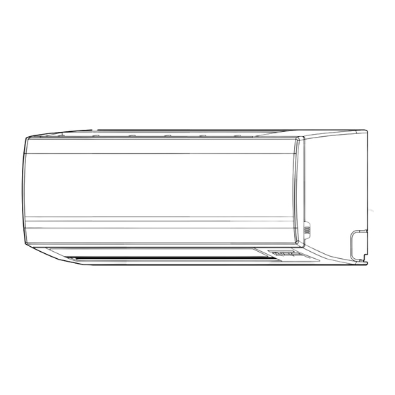
Page 5: Construction Views
FILE NO. SVM-08029 2. CONSTRUCTION VIEWS 2-1. Indoor Unit Air filter Air inlet Front panel Heat exchanger Knock out system Knock out system Installation plate hanger Wireless remote control Installation plate hanger Drain hose (0.50m) Connecting pipe (0.35m) Connecting pipe (0.40m) 12.7mm) (Flare (Flare... -
Page 6: Outdoor Unit
2-2. Outdoor Unit FILE NO. SVM-08029 - 5 -... -
Page 7: Wiring Diagram
FILE NO. SVM-08029 3. WIRING DIAGRAM Infrared rays receiver and indication parts. 3 4 5 6 CN10 CN10 Heat Exchanger GRN&YEL 3 4 5 6 CN14 WP-018 CN07 DB01 Heat Exchanger CN01 Sensor(TC) RY01 DC 12 V Switching Power Supply CN03 Thermo Sensor(TA) Louver motor... -
Page 8: Specification Of Electrical Parts
FILE NO. SVM-08029 4. SPECIFICATION OF ELECTRICAL PARTS 4-1. Indoor Unit Parts name Type Specifications ° Fan motor (for indoor) AC Motor with 145 C thermo fuse AFS- 220-20-4AR ° Thermo sensor (TA-sensor) 10k at 25 C Transformer ST-001 Microcontroller unit (IC30) TMP87CM40ANG Heat exchanger sensor °... -
Page 9: Refrigeration Cycle Diagram
FILE NO. SVM-08029 5. REFRIGERATION CYCLE DIAGRAM Indoor unit Heat exchanger Cooling 0.49 m 0.39 m (Connecting pipe) (Connecting pipe) Æ6.35 Æ12.7 Cross flow fan O.D.:12.7 mm O.D.:6.35 mm Packed valve Packed valve (Æ12.7) (Æ6.35) Cooling Cooling Compressor QK222PCB Capillary tube Æ1.7 x 800 Heat exchanger Refrigerant... -
Page 10: Control Block Diagram
FILE NO. SVM-08029 6. CONTROL BLOCK DIAGRAM Main Unit Control Panel M.C.U. Operation Heat Exchange sensor Functions Display Timer Display Thermo. Sensor • Louver Control Auto Fan Sign Display Infrared Rays Signal Reciver • 3-minutes Delay at Restart for Compressor Filter Sign Display Initiallizing Circuit... -
Page 11: Operation Description
FILE NO. SVM-08029 7. OPERATION DESCRIPTION 1 1 1 7-1. Remote control 7-1-1. Function of Push Button 1 1 1 Infrared signal emitter TOSHIBA Set louver button (FIX) TEMP. MODE Auto louver button (SWING) AUTO AUTO COOL QUIET Mode select button (MODE) AUTO FAN Hr.ON... - Page 12 FILE NO. SVM-08029 7-1-2. Display of Remote Control All indications, except for the clock time indicator, are displayed by pressing the button. Transmission mark Operation Indicate when press the operation This transmission mark indicates when the remote controller transmits signals to the indoor ON/OFF button.
-
Page 13: Outline Of Air Conditioner Control
FILE NO. SVM-08029 • Turning off the compressor and outdoor f an 7-2. Outline of Air Conditioner Control when the outdoor unit receives the shut down This is a fixed capacity type air conditioner, which uses command a AC motor for an indoor fan. The AC motor drive circuit is mounted in the indoor unit. -
Page 14: Description Of Operation Mode
FILE NO. SVM-08029 7-3-2. Cooling operation 7-3. Description of Operation Mode ([MODE] button on the remote control is set (1) When turning on the breaker, the operation lamp to the cooling operation.) blinks. This means that the power is on (or the (1) The compressor, outdoor fan and operation display power supply is cut off.) lamp are controlled as shown in Fig. -
Page 15: Low-Temperature Limit Control
FILE NO. SVM-08029 7-3-4. Automatic operation 7-3-3. Dry operation ([MODE] button on the remote control is set ([MODE] button on the remote control is set to the dry operation.) to the automatic operation.) (1) The compressor, outdoor fan and operation (1) One of 2 operations (Cooling or Fan only) display lamp are controlled as shown in is selected according to difference between the... -
Page 16: Eco Operation
FILE NO. SVM-08029 7-5. ECO Operation Cooling operation · The preset temperature will increase 1ºC after the ECO mode has operated for 1 hour and the temperature will increase another 1ºC after the ECO mode has operated for 2 hour. (the value of the preset temperature on the remote control does not change.) ·... -
Page 17: Auto Restart Function
FILE NO. SVM-08029 7-7. Auto Restart Function This indoor unit is equipped with an automatic restarting function which allows the unit to restart operating with the set operating conditions in the event of a power supply being accidentally shut down. The operation will resume without warning three minutes after power is restored. - Page 18 FILE NO. SVM-08029 7-7-2. How to Cancel the Auto Restart Function To cancel auto restart function, proceed as follows : Repeat the setting procedure : the unit receives the signal and beeps three times. The unit will be required to be turned on with the remote controller after the main power supply is turned off. •...
-
Page 19: Installation Procedure
Also, make sure the equipment is properly earthed. • Appliance shall be installed in accordance with national wiring regulations. If you detect any damage, do not install the unit. Contact your TOSHIBA dealer immediately. CAUTION • Exposure of unit to water or other moisture before installation could result in electric shock. - Page 20 FILE NO. SVM-08029 REQUIREMENT OF REPORT TO THE LOCAL POWER SUPPLIER Please make absolutely sure that the installation of this appliance is reported to the local power supplier before installation. If you experience any problems, or if the installation is not accepted by the supplier, the service agency will take adequate countermeasures.
-
Page 21: Installation Diagram Of Indoor And Outdoor Units
FILE NO. SVM-08029 8-2. Installation Diagram of Indoor and Outdoor Units For the rear left and left piping Hook Installation plate Wall Insert the cushion between the indoor unit and wall, and tilt the indoor unit for better operation. Do not allow the drain hose to get slack. -
Page 22: Installation
FILE NO. SVM-08029 8-3. Installation 8-3-1. Optional installation parts Part Parts name Q'ty Code Refrigerant piping Æ Liquid side : 6.35 mm each Æ Gas side 12.70 mm Pipe insulating material (polyethylene foam, 6 mm thick) Putty, PVC tapes each <Fixing bolt arrangement of outdoor unit>... - Page 23 FILE NO. SVM-08029 8-3-2. Accessory and installation parts Part Part Part Part name (Q’ty) Part name (Q’ty) Part name (Q’ty) Pan head wood screw Installation plate x 1 Remote control holder x 1 ∅3.1 x 16 x 2 Wireless remote control x 1 Active Carbon-Catechin filter x 2 Mounting screw ∅...
-
Page 24: Indoor Unit
FILE NO. SVM-08029 8-4. Indoor Unit 8-4-2. Cutting a hole and mounting installation 8-4-1. Installation place • A place which provides the spaces around the plate indoor unit as shown in the diagram. <Cutting a hole> • A place where there is no obstacle near the air inlet and outlet. - Page 25 FILE NO. SVM-08029 <When the installation plate is directly mounted on 8-4-3. Electrical work the wall> 1. The supply voltage must be the same as the rated 1. Securely fit the installation plate onto the wall by voltage of the air conditioner. screwing it in the upper and lower parts to hook up 2.
- Page 26 FILE NO. SVM-08029 8-4-4. Wiring connection Cord clamp <How to connect the connecting cable> Terminal block Terminal cover Wiring of the connecting cable can be carried out Screw without removing the front panel. Connecting cable 1. Remove the air inlet grille. Open the air inlet grille upward and pull it toward Earth line you.
- Page 27 FILE NO. SVM-08029 8-4-5. Piping and drain hose installation How to fix the drains cap 1) Insert hexagonal wrench (4 mm) in a center <Piping and drain hose forming> head. * Since dewing results in a machine trouble, make sure to insulate both the connecting pipes. (Use polyethylene foam as insulating material.) 4 mm Rear right...
- Page 28 FILE NO. SVM-08029 <Left-hand connection with piping> 8-4-6. Indoor unit fixing Bend the connecting pipe so that it is laid within 43 mm 1. Pass the pipe through the hole in the wall, and hook above the wall surface. If the connecting pipe is laid the indoor unit on the installation plate at the upper exceeding 43 mm above the wall surface, the indoor hooks.
-
Page 29: Outdoor Unit
FILE NO. SVM-08029 8-4-7. Drainage 8-5. Outdoor Unit 1. Run the drain hose sloped downwards. 8-5-1. Installation place • A place which provides the spaces around the NOTE outdoor unit as shown in the left diagram. • Hole should be made at a slight downward slant on •... - Page 30 FILE NO. SVM-08029 8-5-2. Refrigerant piping connection (Unit : N· m) Outer dia. 1. Cut the pipe with a pipe cutter. Tightening torque of copper pipe ∅6.35 16 to 18 (1.6 to 1.8 kgf·m) Roughness Warp Obliquity 90° ∅9.52 30 to 42 (3.0 to 4.2 kgf·m) ∅12.70 50 to 62 (5.0 to 6.2 kgf·m) Fig.
- Page 31 FILE NO. SVM-08029 8-5-3. Evacuating <Packed valve handling precautions> After the piping has been connected to the indoor unit, Open the valve stem all the way out; but do not try · you can perform the air purge together at once. to open it beyond the stopper.
-
Page 32: How To Set Remote Control Selector Switch
FILE NO. SVM-08029 8-6. How to Set Remote Control Selector Switch 8-5-4. Wiring connection When two indoor units are installed in the seperated rooms. 1. Remove the valve cover from the outdoor unit. It is not necessary to change the selector switches. 2. -
Page 33: Others
FILE NO. SVM-08029 8-7. Others 8-7-3. Auto restart setting This product is designed so that, after a power failure, 8-7-1. Gas leak test Check places for it can restart automatically in the same operating mode the indoor unit. as before the power failure. Valve cover Information The product was shipped with Auto Restart function... -
Page 34: Troubleshooting Chart
FILE NO. SVM-08029 9. TROUBLESHOOTING CHART 9-1. Troubleshooting Procedure 9-2-2. Incorrect cable connection between Indoor and outdoor units Follow the details of 9-2. Basic Chec k Items . The indoor unit is connected to the outdoor unit with If there is no trouble corresponding to 9-2, check 5 cables (Heat pump model) or 3 cables (Cooling Only whether or not there are faulty parts following model). -
Page 35: Primary Judgement
FILE NO. SVM-08029 9-3. Primary Judgement 9-3-2. Failure diagnosis The indoor unit diagnoses the operation condition and 9-3-1. Role of indoor unit controller indicates the information of the self-diagnosis with the The indoor unit controller receives the operation lamps on the display panel of the indoor unit. commands from the remote control and executes them. -
Page 36: Self-Diagnosis By Remote Control (Check Code)
FILE NO. SVM-08029 9-4. Self-Diagnosis by Remote Control (Check Code) (1) If the lamps are indicated as shown B to G in Table 9-3-1, exchanger the self-diagnosis by the remote control. (2) When the remote control is set to the service mode, the indoor controller diagnoses the operation condition and indicate the information of the self-diagnosis on the display of the remote... - Page 37 FILE NO. SVM-08029 Table 9-4-1 Block level Diagnosis function Judgement and action Check Check Block Symptom Conditioner Condition code code status Indoor Thermo. sensor Indicated Continued 1.Check thermo sensor. P.C. board short/break. when detected operation. 2.If it is OK, check abnormal P.C.
-
Page 38: Troubleshooting Flowcharts
FILE NO. SVM-08029 9-5. Troubleshooting Flowcharts 9-5-1. Power can not be turned on (No operation at all) <Preliminary checks> Operation (1) Is the supply voltage normal? (2) Is the connection to the AC output OK.? Check Items Main cause Shut off the power supply from AC outlet once and Countermeasure turn it on after 5 seconds. - Page 39 FILE NO. SVM-08029 9-5-2. Power can not be turned on after replacing indoor P.C. board <Checking Procedure> Connect the AC Power supply Return the wiring of the Does the OPERATION Is it wired as shown power relay is returned to lamp blink? in Figure below? the normal procedure.
- Page 40 FILE NO. SVM-08029 9-5-3. Outdoor unit does not operate Shut off the power supply from AC outlet once and turn it on after 5 seconds. Does the OPERATION lamp blink? See "Power can not be turned on". Does the power turn on by pushing See "Power can not be turned on".
-
Page 41: Only Compressor Does Not Operate
FILE NO. SVM-08029 9-5-4. Only compressor does not operate Shut off the power supply from AC outlet once and turn it on after 5 seconds. Does the OPERATION lamp blink? See "Power can not be turned on". Does the power turn on by See "Power can not be turned on". -
Page 42: Only Outdoor Fan Does Not Operate
FILE NO. SVM-08029 9-5-5. Only outdoor fan does not operate Shut off the power supply from AC outlet once and turn it on after 5 seconds. Does the OPERATION lamp blink? See "Power can not be turned on". Does the power turn on by See "Power can not be turned on". - Page 43 FILE NO. SVM-08029 9-5-6. Only the indoor fan does not operate < Check procedure > Shut off the power supply once. Turn the power supply. Does the fan stop in Replace the P.C. board. Control P.C. board is defective. no operating status? Start the operation with low fan setting in cool operation.
-
Page 44: Troubleshooting For Remote Control (Including The Indoor P.c. Board)
FILE NO. SVM-08029 9-6. Troubleshooting for Remote Control (Including the Indoor P.C. Board) There is no been from the indoor unit. Push the [ ] button. The operation lamp of the air conditioner main unit does not light. Does the transmission indicator blink? Reset the remote control by use the tip pencil push... - Page 45 FILE NO. SVM-08029 9-6-1 How to check the P.C. board (2) Inspection procedres 1) When a P.C. board is judged to be defective, (1) Operating precautions check for disconnection, burning, or discolora- 1) When removing the front panel or the P.C. board, tion of the copper foil pattern or this P.C.
- Page 46 FILE NO. SVM-08029 (3) Checking procedure le 9-6-1 ocedure Check Point (Symptom) Causes Shut off the power supply and 1. Is the fuse blown? • Application of shoc oltage. remove the P.C. board assembly load b y shor t-circuit of the •...
- Page 47 FILE NO. SVM-08029 Table 9-6-2 Approximate resistance value of thermo sensor (kΩ) Temperature 0°C 10°C 20°C 25°C 30°C Resistance value 33.8 20.35 12.59 10.00 7.99 9-6-2. w to shor ten time of restart delay timer Press [CLR] button while pressing [CHK] button with a tip of a pencil.
-
Page 48: How To Replace The Main Parts
FILE NO. SVM-08029 10. HOW TO REPLACE THE MAIN PARTS WARNING • Since high voltages pass through the electrical parts, turn off the power without fail before proceeding with the repairs. Electric shocks may occur if the power plug is not disconnected. •... - Page 49 FILE NO. SVM-08029 Part name Procedures Remarks Front panel 4) Press "PUSH" part under the front panel and remove hooks of the front panel from Installation plate the installation plate. Front panel Press 5) Remove the front panel fixing screws. (2 pcs.) 6) Take off three hooks of panel from rear side.
- Page 50 FILE NO. SVM-08029 Part name Procedures Remarks ‚ Electric parts 1) Follow the procedure up to 3) in above. box assembly 2) Remove screw of earth lead attached to the end plate of the evaporator. 3) Remove the lead wire cover, and remove connector for the fan motor and connec- tor for the louver motor from the electric parts box assembly.
- Page 51 FILE NO. SVM-08029 Part name Procedures Remarks ƒ Horizontal louver 1) Remove shaft of the horizontal louver from the back body. (First remove the left shaft, and then remove other shafts while sliding the horizontal louver leftward.) ‚ „ Evaporator 1) Follow to the procedure in the item (Heat exchanger) 2) Remove the pipe holder from the rear side of the main unit.
- Page 52 FILE NO. SVM-08029 Part name Procedures Remarks „ … Bearing 1) Follow to the procedure in the item 2) Remove the two screws used to secure the bearing base. Two screws 3) Remove the bearing base. <Caution at assembling> • If the bearing is out from the housing, push it into the specified position and then incorporate it in the main body.
- Page 53 FILE NO. SVM-08029 Part name Procedures Remarks † „ Fan motor 1) Follow to the procedure till item 2) Loosen the set screw of the cross flow fan. 3) Remove two fixing screws of the motor cover and them remove the motor cover. 4) Remove two more fixing screws of the motor band and remove the motor band.
- Page 54 FILE NO. SVM-08029 Part name Procedures Remarks ‡ Cross flow fan <Caution at reassembling> 5 mm 1) To incorporate the fan motor, remove the fan motor rubber (at shaft core side), incorporate the motor into the position in the following figure, and then install the fan motor.
-
Page 55: Outdoor Unit
FILE NO. SVM-08029 10-2 . . Outdoor Unit Part name Procedures Remarks Common 1. Detachment Upper cabinet procedure 1) Stop operation of the air conditioner, and turn off the main switch and breaker of the Wiring cover air conditioner. 2) Remove the valve cover. (ST1T∅4 x 10s Valve cover 1 pc) •... - Page 56 FILE NO. SVM-08029 Part name Procedures Remarks Fan motor 1) Perform work of item 1 of 1 and 1 of 2. 2) Remove the flange nut fixing the fan motor Fan motor and the propeller fan. Propeller fan • Flange nut is loosened by turning clockwise.
- Page 57 FILE NO. SVM-08029 Part name Procedures Remarks Fan guard 1. Detachment 1) Perform work of item 1 of 1 and 1 of 2. Requirement: Perform the work on a corrugated cardboard, cloth, etc. to prevent scratches to the product. 2) Remove the front cabinet, and place it down so that the fan guard side faces downwards.
-
Page 58: Exploded Views And Parts List
FILE NO. SVM-08029 11. EXPLODED VIEWS AND PARTS LIST 11-1. Indoor Unit (E-Parts Assy) Location Part Location Part Description Description 43T60383 TERMINAL 43T69364 FUSE,TEMPERATURE 43T69004 SENSOR;HEAT EXCHANGER 43T60366 POWER CORD 43T69005 SENSOR;THERMOSTAT 43T62003 CORD CLAMP 43T69641 PC BOARD ASSY; WRS-LED 43T69740 ASM-PCB-SERV - 57 -... -
Page 59: Indoor Unit
FILE NO. SVM-08029 11-2. Indoor Unit Electric Parts Assembly Location Part Location Part Description Description 43T21397 LOUVER MOTOR 43T39328 MOTOR BAND (LEFT) 43T21393 FAN MOTOR 43T39329 MOTOR BAND (RIGHT) 43T22312 MOLD BEARING ASSEMBLY 43T09409 HORIZONTAL LOUVER 43T70313 DRAIN HOSE 43T79313 DRAIN CAP 43T20325 CROSS FLOW FAN ASSEMBLY... -
Page 60: Outdoor Unit
FILE NO. SVM-08029 11-3. Outdoor Unit Location Part Location Part Description Description 43T42335 BASE PLATE ASSEMBLY 43T19335 FAN GUARD 43T41410 COMPRESSOR 43T04304 PARTITION 43T49327 CUSHION,RUBBER 43T39326 MOTOR BASE CONNECTION PLATE 43T97001 43T39325 MOTOR BASE 43T43406 CONDENSER ASSEMBLY 43T19337 PACKED VALVE COVER 43T00448 FIXING PLATE VALVE 43T00481... - Page 61 FILE NO. SVM-03004(1) TOSHIBA CARRIER (THAILAND) CO.,LTD. 144/9 MOO 5, BANGKADI INDUSTRIAL PARK, TIVANON ROAD, TAMBOL BANGKADI, AMPHUR MUANG, PATHUMTHANI 12000, THAILAND. – 75 –...
Need help?
Do you have a question about the RAS-12KSX-1 and is the answer not in the manual?
Questions and answers