
Subscribe to Our Youtube Channel
Related Manuals for MEGATRONIX VS 3525 Viking


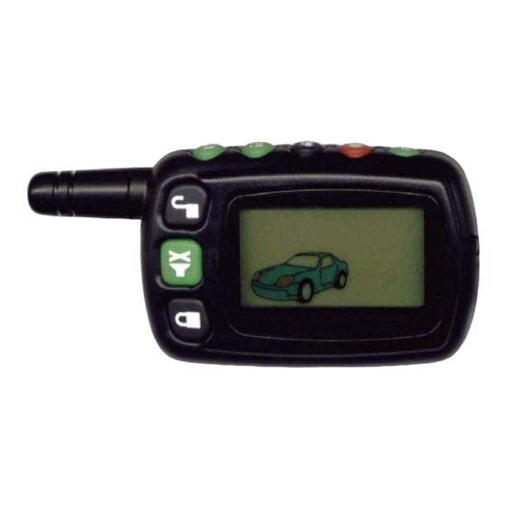
Summary of Contents for MEGATRONIX VS 3525 Viking
- Page 1 APR/16/2002 VS 3525 2-WAY LCD PAGER ALARM WITH REMOTE ENGINE STARTER Installation Manual MEGATRONIX VAN NUYS, CA U.S.A.
-
Page 2: Installer Warnings
APR/16/2002 INTRODUCTION INSTALLER WARNINGS This Remote Starter with Security and Keyless Entry System is designed to be installed on fuel injected vehicles with an automatic transmission ONLY. Never install this remote starter on a manual transmission vehicle. This system must be installed and wired through a safety switch it will not start in any forward or reverse gear. -
Page 3: Installation Diagram
APR/16/2002 INSTALLATION DIAGRAM Optional Pager (Knock) Indicator Sensor 15A Fuse 1. Red/White: Parking Light Relay Power input Two Way 2. White: Parking Light Relay Output Transceiver Antenna 3. Black: Ground to Vehicle Frame 4. Brown: Positive Output to Siren 3A Fuse 8 Pin Black Connector 5. - Page 4 APR/16/2002 #H6. 8 PIN BLACK CONNECTOR FOR INPUT CONNECTION: 1. White/Black Wire: ( ) Negative Safety Shut Down Input for Hood pin 2. Black/White Wire: ( ) Neutral Safety Switch Input & ) Remote Start Toggle Switch Input 3. White/Violet Wire: ( ) Positive Safety Shut Down Input for Brake switch.
-
Page 5: H1: 6 Pin Heavy Gauge Wiring Connection
APR/16/2002 H1: 6 PIN HEAVY GAUGE WIRING CONNECTION: Remember that the system does to start a vehicle is duplicate the functions of the ignition key switch! Below, we will explain the three basic functions of the ignition switch. Since this installation will require analysis of the ignition switch functions, we recommend making the three connections below at the ignition switch harness directly. - Page 6 APR/16/2002 The RED/WHITE wire is the input to the flashing parking light relay. The connection of the RED/WHITE wire will determine the output polarity of the flashing parking light relay. If the vehicle you are working on has +12volt switched parking lights, you don’t need connect this wire. This wire already connected to +12volt.
- Page 7 APR/16/2002 An isolation diode must be used for ground switched brake light circuits and must be connected to the output of the brake switch. Hood Pin Switch To: White/Black Wire / To: Alarm instant trigger Blue wire Negative safety Diode Diode H6/2.
- Page 8 APR/16/2002 (-) Wait To Start Wire (+) Wait To Start Wait to Start White/Green Wire Wait To Start White/Green Wire Indicator Wait To Start Input Indicator Wait To Start Input Ignition (+) H6/6. GREEN WIRE -- NEGATIVE DOOR SWITCH SENSING INPUT -- This wire is the ground trigger input wire for negative door pin switch.
-
Page 9: Gm Vats Key Override
APR/16/2002 Ignition 3 output: Some newer vehicles use a third ignition wire which is required to start and keep the vehicle’s engine running. If this is the case, wire an IGN 3 relay (not supplied) as shown below: Do not connect any vehicle circuits together, they are isolated for a resaon. + 12 V Constant Fused 25A Capable Yellow Wire... -
Page 10: Factory Security Disarm Signal Output
APR/16/2002 Fuse +12V Or Ground CHANNEL 2 Depending On System Requirements Gray Wire +12V Electric Device H9/3. Pink wire –(-) 200ma PROGRAMMABLE OUTPUT (See Start Feature I – 5 Programming) 2 STEPS UNLOCK OUTPUT -- (Factory default setting) The 2 steps unlock feature will work for the most fully electronic door lock circuit. The vehicle must have an electronic door lock switch (not the lock knob or key switch), which locks and unlocks all of vehicle's doors. -
Page 11: Factory Security Rearm Signal Output
APR/16/2002 This wire is provided to use the existing vehicle's FUSE To horn horn as the alarm system's optional's warning audible device. It's a transistorized low current output, and should only be connected to the low Brown/White + 12 V current ground output from the vehicle's horn wire switch. - Page 12 APR/16/2002 VACUUM OPERATED CENTROL LOCKING 5-WIRE ALTERNATING DOOR LOCK Green Wire +12V Green Wire Master Door Door Switch Lock Switch Splice Cut the Existing 3 Pin Plug Unlock Wire +12V To Alarm 3 Pin Splice Plug To Compressor +12V Alarm Cut the Existing Lock Wire To Door...
-
Page 13: Programming Transmitter
APR/16/2002 ROGRAMMING A. PROGRAMMING TRANSMITTER: PROGRAMMING THE REGULAR REMOTE TRANSMITTER Important Note: This program mode is for regular remote transmitter and passive/active transmitter programming only; do not program the TX780V two-way LCD screen transmitter on this mode. Note: This mode will only retain the last 4 remote transmitters programmed. If the transmitter memory is exceeded, the security system will start deleting transmitters from memory in chronological order. -
Page 14: Features Programming
APR/16/2002 TX780V TWO-WAY LCD SCREEN REMOTE TRANSMITTER B. FEATURES PROGRAMMING: ALARM FEATURE “ ” PRORAMMING: 1. Turn the Ignition 'switch ‘ON/OFF’ 3 TIMES and stay in OFF position. 2. Push the Valet switch 2 times and hold it until one chirp with a long chirp is hearing then release the valet switch. -
Page 15: Alarm Feature
APR/16/2002 Exit : Turn Ignition to 'ON' position, or leave it for 15 seconds. A 3 long chirps & 3 parking light flashes to confirm exit. Door Ajar Error Chirp on/off: This feature controls the error chirp that is generated if the system is armed with the door trigger active. This useful in vehicles that has a long dome light delay after the door has been closed. - Page 16 APR/16/2002 Latched output / reset with ignition = The latched / reset with ignition output selection operates just like the latched output but will reset or stop when the ignition is turned on. ALARM FEATURE “ ” PRORAMMING: 1 Turn the Ignition 'switch ‘ON/OFF’ 3 TIMES and stay in OFF position. 2 Push the Valet switch 6 times and hold it until three chirps with a long chirp is hearing then release the valet switch.
- Page 17 APR/16/2002 Delete: Within 15 seconds, Again press and hold the transmitter button for 4 seconds. A [1] long chirps to confirm deleted the sensor code. Password Pin Code Setup: Enter: 1. Turn the Ignition 'switch ‘ON/OFF’ 3 times and stay in OFF position. 2.
- Page 18 APR/16/2002 Press and release the transmitter button again. [2] LED flash, [2] siren/horn chirps to indicate your are in optional sensor (connected to H8 4 pin plug) test mode. 1. Activate the warn-away (first stage optional sensor), system will emit a short chirp. 2.
-
Page 19: Tachometer Checking Type
APR/16/2002 H9/6 Brown/White H9/6 Brown/White Wire = (-) 200ma Wire = Factory Horn Output Security Rearm Signal Output Temperature-Control Temperature-Control Temperature-Control Temperature-Control Starting OFF Starting 5 F ( 15 C) Starting 7 F ( Starting 22 F ( Exit : Turn Ignition to 'ON' position, or leave it for 15 seconds. A 3 long chirps & 3 parking light flashes to confirm exit. - Page 20 APR/16/2002 CHECK LEVEL PROGRAMMING: (TEST and ADJUST) While the system stay in Start Feature “II” programming mode, 1. Press the button on the transmitter to start the vehicle. 2. If everything goes well: a. Press the button on the transmitter to stop engine running. You have been completed this programming successfully.
-
Page 21: Return To Factory Default Setting
APR/16/2002 Timer Checking Type Enter Start Feature ‘II’ Programming Mode: 1. Turn the Ignition 'switch ‘ON/OFF’ 3 TIMES and stay in OFF position. 2. Push the Valet switch 10 times and hold it until five chirps with a long chirp is hearing then release the valet switch. -
Page 22: Testing Your Installation
APR/16/2002 (+) Safety Shutdown input (Brake) or 1. Check H6/3 White/ Violet wire connection. 2. Move the Enable Toggle Switch to “ON” Neutral Safety Switch input fail. position. (If installed.) 3. Move the gear selector to “Park”/ “NEUTRAL” position. 4. Check H6/2 Black/White wire connection. No RPM or TACHOMETER CHECKING TYPE: Check H6/8 White/Red wire connection... -
Page 23: Key In Sensor Circuits
APR/16/2002 control switch wiring. Shown is a typical GM Park/Neutral ECM input circuit. To connect the Remote Start unit to the GM Park/Neutral ECM input: 1. Locate the Orange/Black reference wire in the “C2” connector found at the ECM in GM B Body vehicles or, locate the equivalent reference wire in the vehicle you are installing the Remote Start Unit in. - Page 24 APR/16/2002 H. Connect terminal 85 of the relay to the Drivers Door side of the pin switch wire previously cut in step B. Note: A second 4003 series diode may be required to maintain the integrity of the hood open, shut down circuit.
Need help?
Do you have a question about the VS 3525 Viking and is the answer not in the manual?
Questions and answers