
Related Manuals for MEGATRONIX Megalarm MEGA 680


Summary of Contents for MEGATRONIX Megalarm MEGA 680
- Page 1 MEGA 680 DELUXE 4-CHANNEL KEYLESS ENTRY SYSTEM Installation And Operation Manual MEGATRONIX CALIFORNIA, U.S.A. MEGA 680...
-
Page 2: Installation Diagram
INSTALLATION DIAGRAM H8 10 Pin H1: Main 5 Pin White Harness White H1 5 Pin H8: 10 Pin White Mini Connector White Two Way H7 4 Pin Paging Transceiver H2 3 Pin H2 3 Pin Black Sensor Brown Antenna Brown (Optional) H3 2 Pin Valet Switch... - Page 3 Keep wiring away from moving engine parts, exhaust pipes, and high-tension cable. Tape wires that pass through holes on the firewall to prevent frying electrical. Watch out for sharp edges that may damage wires and causes short circuit. CAUTION: Do not connect the wire harness to the control module until all wiring to vehicle is complete. H1.
- Page 4 H8. 10-PIN MINI CONNECTOR WIRE HARNESS. H8/1. Yellow wire – To Ignition Switched +12V – This wire is connected to a switched 12 volts source. This wire should receive "12 volts" when ignition key is in "ON" and "START" position. When ignition is turned "OFF", this wire should receive "0" voltage. H8/2.
- Page 5 H8/10.Black / White wire – (-) 200mA Dome Light Control Output – This wire becomes grounded when the dome light control circuit is active. The current capacity of this wire is 200mA. This wire can control the operation of the interior lights. An optional 10 Amp relay can be used on this system for interior lights operation.
- Page 6 2 STEP DOOR UNLOCK WIRE CONNECTION FOR VACUUM OPERATED DOOR LOCKING SYSTEM: 5 WIRE ALTERNATING DOOR LOCKS TYPICAL OF MERCEDES BENZ AND AUDI. Locate the wire under the driver's kick panel. Use the + 12V OEM Door Master Lock voltmeter connecting to ground, verify that you have the Switch correct wire with the doors unlocked, the voltmeter will LT.
- Page 7 PROGRAMMING A. THE TRANSMITTERS: Note: This mode will only retain the last 4 remote transmitters programmed. If the transmitter memory is exceeded, the security system will start deleting transmitters from the memory in chronological order. 1. Turn the Ignition switch ‘OFF/ON’ 3 TIMES and stay in the ON position. Within 15 seconds. 2.
- Page 8 Parking light “on” for Parking light “on” for 30 seconds upon an Pathway 30 seconds upon an unlock signal & 10 illumination unlock signal seconds upon a lock feature “off” signal. Exit: Turn Ignition to the 'ON' position, or leave it for 15 seconds. 3 long chirps will confirm exit. Comfort Feature: Some Vehicles have a special “COMFORT feature”.
- Page 9 Latched output: The latched output selection will output a negative signal as soon as the Channel 3 (4) button is pressed and will continue until the button is pressed again. Latched output / reset with ignition: The latched / reset with ignition output selection operates just like the latched output but will reset or stop when the ignition is turned on.
- Page 10 optional sensor sensitivity and sensor without using the traditional arming/disarming procedures to test the sensors. Enter: 1. Turn the Ignition switch ‘ON/OFF’ 3 TIMES and stay in the OFF position. 2. Push the Valet switch 8 times and hold it on the 8 push until four chirps with a long chirp is heard.
-
Page 11: Operation
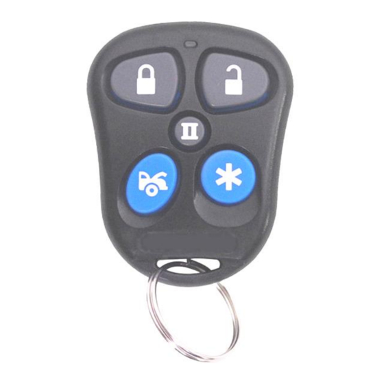
OPERATION: A. TRANSMITTER OPERATION: Transmitter Button System Function Remark Lock Doors and Arm System Press for 1 second Arm and Delete 2 Stage Shock Sensor Press twice within 3 seconds Arm and Noiseless Mode Press three times within 3 seconds Arm System and Hidden Alarm Function Press in sequence within 3 seconds Ignition in "off"... -
Page 12: Passive Arming
sensor bypass mode was activated. The sensor bypass feature is programmed to activate for one arming cycle only. The security system will return to normal operation during the next arming cycle. NOISELESS MODE: Press button once. The siren chirps once. System is now armed. Press button twice more within 3 seconds: Siren chirps once again, system is now in Noiseless mode. - Page 13 5. Turn the Ignition Switch to “Off” position. [4] Chirps form siren/horn, [3] flash from parking light and LED will go off indicating system was disarmed. J. VALET MODE: (System in Disarm or Valet mode): The valet switch allows you to temporarily bypass all alarm functions, eliminating the need to hand your transmitter to parking attendants or garage mechanics.
- Page 14 2. Once the system in car-jacking mode, if you are forced from the vehicle, the system will trigger when the door is opened and closed while the ignition is “ON”. TRIGGER THE ANTI CAR-JACKING MODE: a). 50 seconds after the system has beer triggered. The siren will start chirping for 15 seconds. b).
- Page 15 This device complies with part 15 of the FCC rules. Operation is subject to the following two conditions. (1) This device may not cause harmful interference, and (2) This device must accept any interference received, including interference that may cause undesired operation.
- Page 16 MEGA 680...
Need help?
Do you have a question about the Megalarm MEGA 680 and is the answer not in the manual?
Questions and answers