Table of Contents
Advertisement
Quick Links
Advertisement
Table of Contents

Related Manuals for PowerWalker DC UPS


Summary of Contents for PowerWalker DC UPS
- Page 1 DC UPS User Manual Page 1...
-
Page 2: Table Of Contents
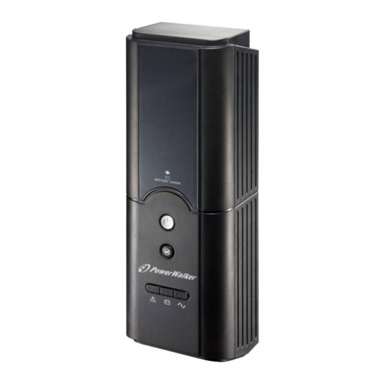
Table of Contents 1. Introduction…………………………………………………………3-4 1.1 General Introduction ……………………………………….………3 1.2 Panel Introduction …………………………………………….……3 1.3 The 7 Pin Terminal Connecters Introduction Table …………….4 2. Safety Information……………………………………………………5 3. Package Contents……………………………………………………6 4. Installation …………………………………………………………7-9 4.1 Wire Connection …………………………………………………7-8 4.2 Wall-Mounting Instructions (Optional) ……………………………9 5. -
Page 3: Introduction
DC to AC. The thoughtful wall-mount design allows you to install DC UPS to diverse environments for maximizing your precious space. DC UPS can be applied to any other device equipped with a compatible DC input connector. -
Page 4: The 7 Pin Terminal Connecters Introduction Table
The rear view DC output socket TheDC outputincludes 12VDCpowe r, AC input socket four dry contact signals and common TheAC input socket is return point for these signals. Please IEC320 C14. findthe definensand wire connections for DC output socket as below table. 1.3 The 7 Pin Terminal Connecters Introduction Table Terminal Function... -
Page 5: Safety Information
Incorrect battery connection or replacement creates risk of explosion. Use only vender approved replacement batteries. The DC UPS is intended for installation and operation in a controlled environment (temperature controlled, indoor area free of conductive contaminants). Refer to specifications in this manual. -
Page 6: Package Contents
3. Package Contents The DC UPS package includes the following items. Please inspect if there are any missing parts. 1 x DC UPS Unit with 12V internal battery preinstalled 1 x User Manual 1 x 7-position connector Page 6... -
Page 7: Installation
4. Installation 4.1 Wire Connection 1. Remove the wire connection cover in the rear of the DC UPS. Keep the cover will and reinstall the cover after all the wires are well-connected. 2. Plug IEC-LOCAL power cord into the AC input socket on the back of DC UPS. - Page 8 (Please refer to “1.3 The 7 Pin Terminal Connecter Intro Table”) (2) Plug the 7-conductor cable into the outlet of the DC UPS (3)Then place the cable between the two sticks for fixing the cable as the following picture 4.
-
Page 9: Wall-Mounting Instructions (Optional)
Step 5. If not, go to Step 4. STEP 3: Insert anchor(s) into the hole(s). STEP 4: Screw in the screw, leaving it protruding 1⁄4 inch from the wall. STEP 5: Mount the DC UPS on the screw heads. Mounting holes Page 9... -
Page 10: Operation
STEP 1: Plug the AC input power cord of the DC UPS into the wall outlet (The utility power outlet) STEP 2: Push the power on/off switch and you may hear a long beep buzzer alarm for knowing the unit is properly turned on. -
Page 11: Available & Visual Alarms
Front-Panel Visual Indicator Audible Description Label Alarm ON A/C Green LED lights None The DC UPS is operating on A/C Testing Green LED None The DC UPS is conducting Battery flashes a self-test. This automatic procedure is normal and will... -
Page 12: Battery Replacement Procedure
Battery Replacement Procedure The DC UPS is designed with an easy-access battery cover. STEP 1 Turn off power switch. Disconnect the DC UPS from power and any connected devices. Remove the battery door on the front of the DC UPS by pulling up the battery door. -
Page 13: Specifications
8. Specifications Model Name DC UPS Nominal input voltage 230Vac INPUT Acceptable Input Voltage Range 80~260Vac Acceptable Input frequency Range 45Hz~65Hz Output power (max) Normal Voltage 12Vdc OUTPUT Output Voltage Range 10.5V~13.8V Line Mode Efficiency > 80% Type/Rating 12V/7Ah x 1pc Discharge Prevention 10.5V ±... - Page 14 Switch on Buzzer disable MUTE FUNCTION Switch off Buzzer enable Operating temperature 0℃ to 40℃ OPERATING Operating humidity 0% to 90% ENVIRONMENT Operating Elevation 0 to 3000m Weight 3.5 kgs PHYSICAL 120mm(W) x 358mm(H) x Dimension (W x H x D) 86.5mm(D) INPUT TYPE IEC inlet...
Need help?
Do you have a question about the DC UPS and is the answer not in the manual?
Questions and answers