
Related Manuals for Planet GSW-4804SF


Summary of Contents for Planet GSW-4804SF
- Page 1 User’s Manual of GSW-4804SF User's Manual GSW-4804SF 48-Port 10/100/1000Mbps with 4-Port Shared SFP Web Smart Switch...
-
Page 2: Fcc Warning
PLANET has made every effort to ensure that this User's Manual is accurate; PLANET disclaims liability for any inaccuracies or omissions that may have occurred. -
Page 3: Table Of Contents
User’s Manual of GSW-4804SF TABLE OF CONTENTS 1. INTRODUCTION ..................................6 1.1 Packet Contents ................................6 1.2 How to Use This Manual..............................6 1.3 Product Feature ................................7 1.4 Product Specification ...............................8 2. INSTALLATION..................................10 2.1 Product Description ...............................10 2.1.1 Product Overview ..............................10 2.1.2 Switch Front Panel .............................. 11 2.1.3 LED Indications .............................. - Page 4 User’s Manual of GSW-4804SF 4.3.5 Link Test ................................42 4.3.6 Buffer Schedule ..............................43 4.4 Redundancy...................................44 4.5 Security..................................45 4.5.1 ACL..................................47 4.5.2 Security Defernce ..............................55 4.5.3 ARP Defernce ..............................56 4.5.4 VLAN ...................................57 4.5.5 MAC Address Binding............................66 4.5.6 MAC Address Filtering ............................68 4.5.7 MAC Address Learning............................69 4.5.8 MAC Address Aging Time ............................70...
- Page 5 User’s Manual of GSW-4804SF APPENDIX B ....................................104 802.1Q VLAN Multi-Untagged VLAN setting sample 1 ..................104 802.1Q VLAN Multi-Untagged VLAN setting sample 2 ..................109 802.1Q VLAN Multi-Untagged VLAN setting sample 3 ..................111 ...
-
Page 6: Introduction
1. INTRODUCTION Thank you for purchasing PLANET 48-Port 10/100/1000Mbps with 4-Port shared SFP Web Smart Switch- GSW-4804SF. In the following section, the term “Switch” means the Switch, i.e. GSW-4804SF; term of “switch” can be any third part switches. 1.1 Packet Contents Check the contents of your package for following parts: •... -
Page 7: Product Feature
User’s Manual of GSW-4804SF 1.3 Product Feature Physical Port 48-Port 10/100/1000Base-T RJ-45 4 SFP slots, shared with Port-45, Port-46, Port-47 and Port-48 RS232 Console interface for reset system to factory default mode Layer 2 Features Complies with the IEEE 802.3, IEEE 802.3u, IEEE 802.3ab, IEEE 802.3z Gigabit Ethernet standard Per port supports Auto-negotiation, 10Base-T / 100Base-TX Half-Duplex / Full-Duplex modes and 1000Base-T Full-Duplex mode. -
Page 8: Product Specification
User’s Manual of GSW-4804SF 1.4 Product Specification GSW-4804SF Product 48-Port 10/100/1000Mbps with 4-Port Shared SFP Web Smart Switch Hardware Specification 48-10 / 100 / 1000Base-T RJ-45 Auto-MDI/MDI-X ports Copper Ports 4 SFP interfaces, shared with Port-45, Port-46, Port-47 and Port-48... - Page 9 User’s Manual of GSW-4804SF IEEE 802.3 10Base-T IEEE 802.3u 100Base-TX IEEE 802.3ab Gigabit 1000Base-T Standards Compliance IEEE 802.3z Gigabit SX/LX IEEE 802.3x Flow Control and Back pressure IEEE 802.1p Class of service IEEE 802.1Q VLAN Tagging Physical Specifications 430 x 350 x 45mm (W x D x H), 1U height Dimensions 4.94 kg...
-
Page 10: Installation
Enterprise and Network Servers, with 96Gbps switching fabric, the GSW-4804SF can handle extremely large amounts of data in a secure topology linking to a backbone or high capacity servers. The powerful QoS and Network Security features make GSW-4804SF to meets the needs of effective data traffic control for ISP and Enterprise, such as VoIP, video streaming and multicast application. -
Page 11: Switch Front Panel
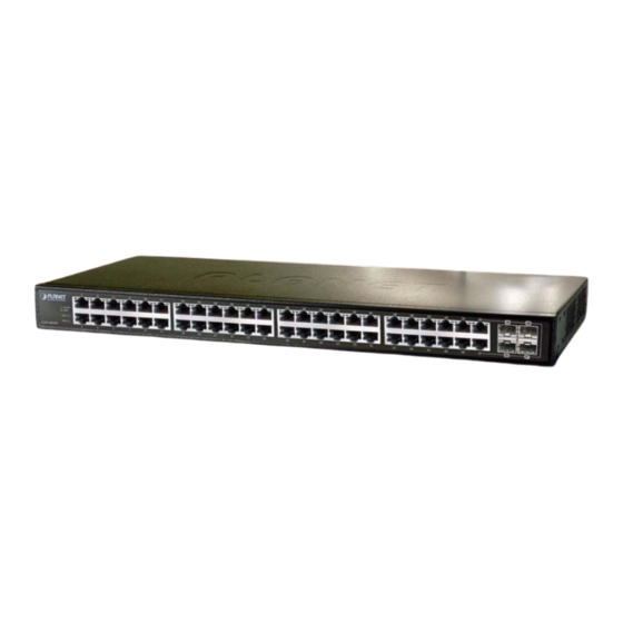
Switch, it consists of 48 Auto Negotiation 10/100/1000Mbps RJ-45 ports with Auto MDI / Figure 2-1 MDI-X feature, four shared Gigabit SFP interfaces with port 45 to port 48 and LED indicators. 10/100 1000 Figure 2-1 GSW-4804SF front panel 2.1.3 LED Indications 2.1.3.1 LED Indications ■ System... -
Page 12: Install The Switch
User’s Manual of GSW-4804SF 2.2 Install the Switch This section describes how to install the Switch and make connections to the Switch. Please read the following topics and perform the procedures in the order being presented. To install your Switch on a desktop or shelf, simply complete the following steps. -
Page 13: Rack Mounting
User’s Manual of GSW-4804SF 2.2.2 Rack Mounting To install the Switch in a 19-inch standard rack, please follows the instructions described below. Step1: Place the Switch on a hard flat surface, with the front panel positioned towards the front side. -
Page 14: Installing The Sfp Transceiver
Figure 2-5 Figure 2-5 Plug-in the SFP transceiver Approved PLANET SFP Transceivers PLANET GSW-4804SF supports both Single-mode and Multi-mode SFP transceiver. The following list of approved PLANET SFP transceivers is correct at the time of publication: ■ MGB-GT SFP (1000Base-T SFP transceiver ) ■... - Page 15 User’s Manual of GSW-4804SF Connect the fiber cable Attach the duplex LC connector on the network cable into the SFP transceiver. Connect the other end of the cable to a device – switches with SFP installed, fiber NIC on a workstation or a Media Converter.
-
Page 16: Configuration
User’s Manual of GSW-4804SF 3. CONFIGURATION This chapter explains the methods that you can use to configure management access to the Switch. It describes the types of management applications and the communication and management protocols that deliver data between your management device (work-station or personal computer) and the system. -
Page 17: Administrator Console Access
User’s Manual of GSW-4804SF 3.2 Administrator Console Access The administration console is a local connection method between the administrator PC and the Switch. Using this method, you can reset the Switch to factory default mode from a personal computer, Apple Macintosh, or workstation connected to the Switch's console (Serial) port. -
Page 18: Reset To Factory Default Mode Under Console Interface
Once, lose or forget the current IP address or login username / password. Once the terminal has connected to the Switch, power on the Switch, the terminal will display that is perform the loading GSW-4804SF program procedures. When the “ Waiting 2 seconds : Press <d> for default parameters” text appears, please press “d” from your keyboard then the Switch... -
Page 19: Web Management Access
User’s Manual of GSW-4804SF 3.4 Web Management Access The PLANET GSW-4804SF provides built-in browser interface. You can manage the Switch remotely by having a remote host with Web browser, such as Microsoft Internet Explorer, Netscape Navigator or Mozilla Firefox. The following shows how to startup the Web Management of the Switch, please note the Switch is configured through an Ethernet connection, make sure the manager PC must be set on the same IP subnet address, for example, the default IP address of the Switch is 192.168.0.100 (the factory-default IP address), then the manager PC should be set at 192.168.0.x... -
Page 20: Management Architecture
User’s Manual of GSW-4804SF Figure 3-3 Web Main Screen of GSW-4804SF Now, you can use the Web management interface to continue the Switch management, please refer to chapter 4 from user manual for more. For security reason, please change and memorize the new password after this first setup. -
Page 21: Web Configuration
4. WEB CONFIGURATION The PLANET GSW-4804SF can be configured through an Ethernet connection, make sure the manager PC must be set on same the IP subnet address with the Switch. For example, if you have changed the default IP address (192.168.0.100) of the Switch to 192.168.1.1 with subnet mask 255.255.255.0 via Web interface, then the manager PC should be set at 192.168.1.x... - Page 22 User’s Manual of GSW-4804SF Figure 4-2 Web Login Screen of GSW-4804SF After entering the username and password, the main screen appears as Figure 4-3. Figure 4-3 Web Main Screen of GSW-4804SF It is recommended to use Internet Explore 5.0 or above to access the Switch.
-
Page 23: Home
User’s Manual of GSW-4804SF The nine items and it description shown as below: Home: Provide Web Main Screen of the Switch. ◆ Explained in section 4.1. System: Provide System configuration of the Switch. ◆ Explained in section 4.2. Port Management: Provide Port Management configuration of the Switch. -
Page 24: System
User’s Manual of GSW-4804SF 4.2 System This section provides IP Address, System Information, Password, Console, Management VLAN, System Upgrade, Parameters Saving, Backup & Recovery, Load Default, Reboot and the screen appears as Figure 4-5 Table 4-1 describes the System object of the Switch. -
Page 25: Ip Address
User’s Manual of GSW-4804SF 4.2.1 IP Address This section allows modify the IP Address, Subnetmask and Gateway. After setup complete, press “Apply” button to take affect. The screen in appears. Figure 4-6 Figure 4-6 IP Address Web Screen 4.2.2 System Information This section displays the System Information and the screen in appears. -
Page 26: Console
User’s Manual of GSW-4804SF 4.2.4 Console This section displays the console baudrate setting information and the screen in appears. Figure 4-9 Figure 4-9 Console Web Screen 4.2.5 Management VLAN This section provides the Management VLAN configuration, after setup complete. Press “Apply” button to take affect and the screen in appears. - Page 27 User’s Manual of GSW-4804SF Press “Browser” button to find the firmware location administrator PC, the screen in appears. Figure 4-12 Figure 4-12 System Upgrade Web Screen After find the firmware location from administrator PC, press “Update” button to start the firmware upgrade process. The screen appears.
- Page 28 User’s Manual of GSW-4804SF The following firmware upgrade screen in appears. Figure 4-15 & 4-16 Figure 4-15 System Upgrade Web Screen Figure 4-16 System Upgrade Web Screen When the screen above appears, please reboot the Switch for take affect. After power on completed, then you can start use the latest firmware of GSW-4804SF.
-
Page 29: Parameters Saving
User’s Manual of GSW-4804SF 4.2.7 Parameters Saving This section allows save current configuration and press “Save” button to take affect and the screen in appears. Figure 4-17 Figure 4-17 Parameters Saving Web Screen At the same time, the Parameters Saving message appears under console inetrface and the screen in appears. -
Page 30: Backup / Recovery
User’s Manual of GSW-4804SF 4.2.8 Backup / Recovery This section allows backup / recover configuration and the screen in appears. This is a useful method for configure Figure 4-19 multi-Switch devices with the same configuration in a short time. Figure 4-19 Backup / Recovery Web Screen... - Page 31 User’s Manual of GSW-4804SF Figure 4-21 Backup Web Screen Figure 4-22 Backup Web Screen -31-...
- Page 32 User’s Manual of GSW-4804SF Recovery Press “Browser” button to find the backup configuration file location of administrator PC, the screen in appears. Figure 4-23 Figure 4-23 Recovery Web Screen After find the backup configuration file location from administrator PC. The screen in appears.
- Page 33 User’s Manual of GSW-4804SF Figure 4-26 Recovery Web Screen When the “Upgrade Done,Please restart your system!” text appears in Recovering Status. Please power off and power on the Switch for take affect, the screen in appears. Figure 4-27 Figure 4-27 Recovery Web Screen...
-
Page 34: Load Default
User’s Manual of GSW-4804SF 4.2.9 Load Default This section allows reset the Switch to factory default mode, press “Apply” button and reboot the Switch to take affect and the screen in appears. Figure 4-28 Figure 4-28 Load Default Web Screen 4.2.10 Reboot... -
Page 35: Port Management
User’s Manual of GSW-4804SF 4.3 Port Management This section provides Port Configuration, Port Statistics, Band Restricting, Cascade Connecting, Link Test, Buffer Schedule, and the screen appears as describes the Port Management object of the Switch. Figure 4-30 Table 4-2 Figure 4-30 Port Management Web Screen... -
Page 36: Port Configuration
User’s Manual of GSW-4804SF 4.3.1 Port Configuration This section provide per port configuration, such as Management Status Disable or Enable, Speed duplex mode selection, Flow Control Disable or Enable. After setup completed, press “Apply” button to take affect. Also provide per port status and the screen in appears. - Page 37 User’s Manual of GSW-4804SF Object Description Port Configuration Allow choose one or multi-ports for configuration. Port List Management Status Allow choose Disable or Enable for one or multi-ports, the default mode is Enable. Speed/ Duplex Allow defining various speed duplex modes for each port, the available options are Auto, 10H, 10F, 100H, 100F, 1000F.
-
Page 38: Port Statistics
User’s Manual of GSW-4804SF 4.3.2 Port Statistics This section display per port detail Statistics and the screen in appears. describes the Port Statistics Figure 4-32 Table 4-4 object of the Switch. Figure 4-32 Port Statistics Web Screen -38-... - Page 39 User’s Manual of GSW-4804SF Object Description Port Indicate the port 1 to port 48 of the Switch. Management Status Display per port Management Status of the Switch. Link Status Display per port Link Status of the Switch. Total Bytes Of Received Packages Display per port received packages value (Unit: Bytes) of the Switch.
-
Page 40: Band Restricting
User’s Manual of GSW-4804SF 4.3.3 Band Restricting This section provide per port Band Restricting configuration and the screen in appears. describes the Figure 4-34 Table 4-6 Band Restricting configuration object of the Switch. Figure 4-34 Band Restricting Web Screen Object... -
Page 41: Cascade Connecting
User’s Manual of GSW-4804SF 4.3.4 Cascade Connecting This section allows assign per port as Cascade Stage Port configuration and the screen in appears. Figure 4-35 Table 4-7 describes the Cascade Connecting configuration object of the Switch. Figure 4-35 Cascade Connecting Web Screen... -
Page 42: Link Test
User’s Manual of GSW-4804SF 4.3.5 Link Test This section provides per port Link Status and the screen in appears. describes the Link Status object of Figure 4-36 Table 4-8 the Switch. Figure 4-36 Link Test Web Screen Object Description Select Port Port Number Allow choose one port for Link Test. -
Page 43: Buffer Schedule
User’s Manual of GSW-4804SF 4.3.6 Buffer Schedule This section provides Buffer Schedule for the system and the screen in appears. describes the Buffer Figure 4-37 Table 4-9 Schedule object of the Switch. Figure 4-37 Buffer Schedule Web Screen Object Description... -
Page 44: Redundancy
User’s Manual of GSW-4804SF 4.4 Redundancy This section provides Link Aggregation Configuration and the screen appears as describes the Figure 4-38and Table 4-10 Link Aggregation object of the Switch. The Link Aggregation lets you group up to eight consecutive ports into a single dedicated connection. This feature can expand bandwidth to a device on the network. -
Page 45: Security
User’s Manual of GSW-4804SF Object Description Aggregation Group Allow choose one Aggregation Group for further configuration of the Switch. Port List Indicate port 1 to port 48 of the Switch. Member Ports Display the Member Ports from per Aggregation Group of the Switch. - Page 46 User’s Manual of GSW-4804SF Object Description Allow define the Access Control List Configuration of the Switch. Explained in section 4.5.1. Allow define the Security Defence Policy of the Switch. Explained in section 4.5.2. Security Defence ARP Defence Allow define the ARP Defence Configuration of the Switch.
-
Page 47: Acl
User’s Manual of GSW-4804SF 4.5.1 ACL This section provides ACL configuration and View ACL Table. An ACL consists of a set of rules which are matched sequentially against a packet. When a packet meets the match criteria of a rule, the specified rule action (Permit / Deny) is taken and the additional rules are not checked for a match. - Page 48 User’s Manual of GSW-4804SF ACL Type: MAC This section provide MAC ACL configuration, the screen in appears and describes the MAC ACL Figure 4-41 Table 4-12 Configuration object of the Switch. Figure 4-41 MAC ACL Configuration Web Screen Object Description Provide various ACL type and available options are MAC, IP, TCP, UDP, ICMP.
- Page 49 User’s Manual of GSW-4804SF Figure 4-42 ACL Policy Setup Web Screen Object Description Add QoS Policy Allow input the new policy name and maximum length is 10 characters. Policy Name Average (1-1000Mbps) Allow input the average value and available range is 1-1000Mbps.
- Page 50 User’s Manual of GSW-4804SF ACL Type: IP (Default) This section provide IP ACL configuration, the screen in appears and describes the IP ACL Figure 4-43 Table 4-14 Configuration object of the Switch. Figure 4-43 IP ACL Configuration Web Scree Object Description Provide various ACL type and available options are MAC, IP, TCP, UDP, ICMP.
- Page 51 User’s Manual of GSW-4804SF ACL Type: TCP This section provide TCP ACL configuration, the screen in appears and describes the TCP ACL Figure 4-44 Table 4-15 Configuration object of the Switch. Figure 4-44 TCP ACL Configuration Web Screen Object Description ACL Type: Provide various ACL type and available options are MAC, IP, TCP, UDP, ICMP.
- Page 52 User’s Manual of GSW-4804SF ACL Type: UDP This section provide UDP ACL configuration, the screen in appears and describes the UDP ACL Figure 4-45 Table 4-16 Configuration object of the Switch. Figure 4-45 UDP ACL Configuration Web Screen Object Description ACL Type: Provide various ACL type and available options are MAC, IP, TCP, UDP, ICMP.
- Page 53 User’s Manual of GSW-4804SF ACL Type: ICMP This section provide ICMP ACL configuration, the screen in appears and describes the ICMP ACL Figure 4-46 Table 4-17 Configuration object of the Switch. Figure 4-46 ICMP ACL Configuration Web Screen Object Description ACL Type: Provide various ACL type and available options are MAC, IP, TCP, UDP, ICMP.
- Page 54 User’s Manual of GSW-4804SF View ACL Table This section provide view the ACL Table, the screen in appears and describes the ACL Table object of Figure 4-47 Table 4-18 Switch Figure 4-47 View ACL Table Web Screen Object Description Index Display the configured ACL Policy.
-
Page 55: Security Defernce
User’s Manual of GSW-4804SF 4.5.2 Security Defernce This section provides Security Defence Configuration and allow choose various Security Defence rules or user defines their own Security Defence rules for powerfull Security Defence ability under TCP / UDP port. The screen in appears. -
Page 56: Arp Defernce
User’s Manual of GSW-4804SF 4.5.3 ARP Defernce This section provides ARP Defence Configuration and allow define ARP Attack Defence Time. The screen in Figure 4-49 appears. describes the ARP Defence object of the Switch. Table 4-20 Figure 4-49 ARP Attack Defence Web Screen... -
Page 57: Vlan
User’s Manual of GSW-4804SF 4.5.4 VLAN This section provides VLAN Configuration and the available options are 802.1Q VLAN and Port-Based VLAN. Before use the VLAN Configuration, please read following VLAN theorem completely before continuing. VLAN Description A Virtual Local Area Network (VLAN) is a network topology configured according to a logical scheme rather than the physical layout. - Page 58 User’s Manual of GSW-4804SF IEEE 802.1Q VLANs IEEE 802.1Q (tagged) VLAN are implemented on the Switch. 802.1Q VLAN require tagging, which enables them to span the entire network (assuming all switches on the network are IEEE 802.1Q-compliant). VLAN allow a network to be segmented in order to reduce the size of broadcast domains. All packets entering a VLAN will only be forwarded to the stations (over IEEE 802.1Q enabled switches) that are members of that VLAN, and this includes...
- Page 59 User’s Manual of GSW-4804SF The Ether Type and VLAN ID are inserted after the MAC source address, but before the original Ether Type/Length or Logical Link Control. Because the packet is now a bit longer than it was originally, the Cyclic Redundancy Check (CRC) must be recalculated.
-
Page 60: Q Vlan Configuration
User’s Manual of GSW-4804SF 802.1Q VLAN Configuration There are up to 256 configurable VLAN groups. By default when 802.1Q is enabled, all ports on the switch belong to default VLAN (VID 1). The default VLAN cannot be deleted. Understand nomenclature of the Switch Tagging and Untagging Every port on an 802.1Q compliant switch can be configured as tagging or untagging. - Page 61 User’s Manual of GSW-4804SF Port Mode VLAN Membership Frame Leave Untagged Belongs to a single untagged VLAN Access ( Tag=PVID be removed) Allowed to belongs to multiple untagged Untagged Always Untag VLANs at the same time (Tag=PVID be removed) Allowed to belongs to multiple Tagged...
- Page 62 User’s Manual of GSW-4804SF 2. If you want to configure port #2 to be in a VLAN other than default VLAN. Double click on “port2” to enter into VLAN port configuration window. Figure 4-52 802.1Q VLAN Port Configuration Web Screen 3.
- Page 63 User’s Manual of GSW-4804SF 5. Trunk configuration: If the Trunk type is chosen, please follow the steps to set the Trunk of the port. 5.1 Add and define the names and VIDs for new VLANs. The VID number ranges from 2 to 4094. Fill the VID field and the VLAN Name field in the Set VLAN’s VID &...
- Page 64 User’s Manual of GSW-4804SF 5.6 As shows in the following screen: Figure 4-58 Show VLAN Members Web Screen Port-based VLAN Configuration Packets can only be broadcast among other members of the same VLAN group. Note all unselected ports are treated as belonging to the default system VLAN.
- Page 65 User’s Manual of GSW-4804SF Figure 4-61 Port-Based VLAN Configuration Web Screen 6. Click on the “Close” button and back to the Port-based VLAN main page. The “Show VLAN Member” button is to list the valid VLANs. You can also remove the added VALN by click on this button.
-
Page 66: Mac Address Binding
User’s Manual of GSW-4804SF 4.5.5 MAC Address Binding This section provides MAC Address Binding Configuration and the screen in appears. describes the Figure 4-64 Table 4-21 MAC Address Binding object of the Switch. This function is based upon for the Switch security. When you add one MAC Address is bind with one port. It remains in the switch's address table, regardless of whether the device is physically connected to the switch. - Page 67 User’s Manual of GSW-4804SF Object Description Bind New MAC Address MAC Address Allow input the MAC Address and the format must be “XX-XX-XX-XX-XX-XX”. Port Choose one specific port for new input MAC Adress binding. Add button Press this button to add the new input MAC Address binding on one specific port.
-
Page 68: Mac Address Filtering
User’s Manual of GSW-4804SF 4.5.6 MAC Address Filtering This section provides MAC Address Filtering Configuration and the screen in appears. describes the Figure 4-65 Table 4-22 MAC Address Filtering object of the Switch. The MAC address Filtering allows the Switch to drop unwanted traffic. Traffic is filtered based on the destination addresses. -
Page 69: Mac Address Learning
User’s Manual of GSW-4804SF 4.5.7 MAC Address Learning This section provides MAC Address Learning Configuration and the screen in appears. describes the Figure 4-66 Table 4-23 MAC Address Learning object of the Switch. The Switch is able to disable MAC Address learning function on ports. -
Page 70: Mac Address Aging Time
User’s Manual of GSW-4804SF 4.5.8 MAC Address Aging Time This section provides MAC Address Aging Time Configuration and the screen in appears. describes Figure 4-67 Table 4-24 the MAC Address Aging Time object of the Switch. The Aging Time affects the learning process of the Switch. Dynamic forwarding table entries, which are made up of the source and destination MAC addresses and their associated port numbers, are deleted from the table if they are not accessed within the aging time. -
Page 71: Qos
User’s Manual of GSW-4804SF 4.6 QoS This section provides QoS Configuration, such as 802.1p-Queue Mapping, Port Default Priority, Queue Management, Trust Mode and the screen appears as describes the QoS object of the Switch. Figure 4-68 Table 4-25 Figure 4-68 QoS Web Screen... -
Page 72: Understand Qos
User’s Manual of GSW-4804SF Understand QOS Quality of Service (QoS) is an advanced traffic prioritization feature that allows you to establish control over network traffic. QoS enables you to assign various grades of network service to different types of traffic, such as multi-media, video, protocol-specific, time critical, and file-backup traffic. -
Page 73: P-Queue Mapping
User’s Manual of GSW-4804SF 4.6.1 802.1p-Queue Mapping This section provides 802.1p-Queue Mapping Configuration and the screen in appears. describes the Figure 4-69 Table 4-26 802.1p-Queue Mapping object of the Switch. Figure 4-69 802.1p-Queue Mapping Web Screen Object Description 802.1p-Queue Mapping Configuration 802.1p Priority (0-7) -
Page 74: Port Default Priority
User’s Manual of GSW-4804SF 4.6.2 Port Default Priority This section provides Port Default Priority Configuration and the screen in appears. describes the Port Figure 4-70 Table 4-27 Default Priority object of the Switch. Figure 4-70 Port Default Priority Web Screen... -
Page 75: Queue Management
User’s Manual of GSW-4804SF 4.6.3 Queue Management This section provides Queue Management Configuration and the screen in appears. describes the Figure 4-71 Table 4-28 Queue Management object of the Switch. Figure 4-71 Queue Management Web Screen Object Description Queue Rule Configuration... -
Page 76: Turst Mode
User’s Manual of GSW-4804SF 4.6.4 Turst Mode This section provides Turst Mode Configuration and the screen in appears. describes the Turst Mode Figure 4-72 Table 4-29 object of the Switch. Figure 4-72 Turst Mode Web Screen Object Description Trust Mode Setup... -
Page 77: Multicast
User’s Manual of GSW-4804SF 4.7 Multicast This section provides Multicast Configuration, such as IGMP Snooping, Static Routing Port and the screen appears as Figure describes the Multicast object of the Switch. 4-73 Table 4-30 Figure 4-73 Multicast Web Screen Object... - Page 78 User’s Manual of GSW-4804SF The format of an IGMP packet is shown below: IGMP Message Format Octets Checksum Type Response Time Group Address (all zeros if this is a query) The IGMP Type codes are shown below: Type Meaning Membership Query (if Group Address is 0.0.0.0)
- Page 79 User’s Manual of GSW-4804SF Non-Member Leave Group Leave Group (Stop Timer) Join Group (Send Report, Start Timer) Query Received (Start Timer) Delaying Member Idle Member Report Received (Stop Timer) Timer Expried (Send report) IGMP State Transitions -79-...
-
Page 80: Igmp Snooping
User’s Manual of GSW-4804SF 4.7.1 IGMP Snooping This section provides IGMP Snooping Configuration and the screen in appears. describes the IGMP Figure 4-74 Table 4-31 Snooping object of the Switch. Figure 4-74 IGMP Snooping Web Screen Object Description Status Config IGMP Snooping Status: Provide IGMP Snooping Disable or Enable. -
Page 81: Static Routing Port
User’s Manual of GSW-4804SF 4.7.2 Static Routing Port This section provides Static Routing Port Configuration and the screen in appears. describes the Figure 4-75 Table 4-32 Static Routing Port object of the Switch. Figure 4-75 Static Routing Port Web Screen... -
Page 82: Network Analysis
User’s Manual of GSW-4804SF 4.8 Network Analysis This section provides Network Analysis configuration, such as Port Analysis, Port Mirror, QoS Statistics, ARP Attack Log and the screen appears as describes the Network Analysis object of the Switch. Figure 4-76 Table 4-33... -
Page 83: Port Analysis
User’s Manual of GSW-4804SF 4.8.1 Port Analysis This section provides display Per Port detail traffic transmits / receives statistics and the screen in appears. Figure 4-77 Table describes the Port Analysis object of the Switch. 4-34 Figure 4-77 Port Analysis Web Screen... - Page 84 User’s Manual of GSW-4804SF Object Description Port Selecting Port Allow choose one port for detail traffic transmits / receives statistics display. Apply button Press this button to take affect. Show Statistic Table Statistics Item Tx bytes: Displays the value of packets transmits from choose port and the unit is bytes.
-
Page 85: Port Mirror
User’s Manual of GSW-4804SF 4.8.2 Port Mirror This section provides Port Mirror configuration and Port Mirroring is a method of monitoring network traffic that forwards a copy of each incoming and/or outgoing packet from one port of a network switch to another port where the packet can be studied. -
Page 86: Qos Statistics
User’s Manual of GSW-4804SF 4.8.3 QoS Statistics This section provides QoS Statistics and the screen in appears. describes the QoS Statistics object of Figure 4-79 Table 4-36 the Switch. Figure 4-79 QoS Statistics Web Screen Object Description QoS Statistics Name of Statistics Display the name of Statistics, . -
Page 87: Arp Attack Log
User’s Manual of GSW-4804SF 4.8.4 ARP Attack Log This section provides ARP Attack Log information and the screen in appears. describes the ARP Figure 4-80 Table 4-37 Attack Log object of the Switch. Figure 4-80 ARP Attack Log Web Screen... -
Page 88: Network Equipment
User’s Manual of GSW-4804SF 4.9 Network Equipment This section provides Network Equipment configuration, such as Host Security Defense, Facility Protection, Program Priority, and the screen appears as describes the Network Equipment object of the Switch. Figure 4-81 Table 4-38 Figure 4-81 Network Equipment Web Screen... -
Page 89: Host Security Defense
User’s Manual of GSW-4804SF 4.9.1 Host Security Defense This section provides Host Security Defense configuration and the screen in appears, the available options are Figure 4-82 Host Security Defense, Add Network Equipment, View Network Device Attribute and Network list. Please refer to following sections for detail explanation. - Page 90 User’s Manual of GSW-4804SF Add Network Equipment This section provide Add Network Equipment configuration, there are two methods to add the Network equipment, such as Auto Search and Manual Add, please refer to following detail information. Auto Search This section provide Auto search the network equipment during one specific IP address range and VLAN, the screen in...
- Page 91 User’s Manual of GSW-4804SF Object Description Manual Add IP Address: Allow input one specific IP address of the equipment. MAC Address: Allow input one specific MAC address of the equipment. VLAN: Allow input one specific VLAN group includes the port that equipment connected.
- Page 92 User’s Manual of GSW-4804SF Network Device List This section provide Network Device List configuration, the screen in appears and describes the Figure 4-87 Table 4-43 Network Device List object of the Switch. Figure 4-87 Network Device List Web Screen Object...
- Page 93 User’s Manual of GSW-4804SF Figure 4-88 Batch Limit Web Screen Object Description Limited Quantities Flow Setup Start-up IP Address Allow input a start IP address for Limited Quantities Flow Setup. End up IP Address Allow input an end IP address for Limited Quantities Flow Setup.
-
Page 94: Facility Protection
User’s Manual of GSW-4804SF 4.9.2 Facility Protection This section provides Facility Protection configuration and the screen in appears. describes the Figure 4-92 Table 4-45 Facility Protection object of the Switch. Figure 4-92 Facility Protection Web Screen -94-... - Page 95 User’s Manual of GSW-4804SF Object Description Host Bandwidth Restriction Enable Host←→Router Bandwidth Restriction Allow Disable or Enable the Router Bandwidth Restriction, default is Disable. Apply button Press this button to take affect. DHCP Server Protection Enable DHCP Server Protection Function Allow Disable or enable the DHCP Server Protection Function, default is Disable.
-
Page 96: Programme Priority
User’s Manual of GSW-4804SF 4.9.3 Programme Priority This section provides Programme Priority configuration and the screen in appears. describes the Figure 4-93 Table 4-46 Programme Priority object of the Switch. Figure 4-93 Programme Priority Web Screen -96-... - Page 97 User’s Manual of GSW-4804SF Object Description Programme Priority Level Template Application Programme Provide six various Programme Template application and available options are Template: WOW. CGL. POPO.QQ Voice. Lineagell. CS. Default is WOW. Also provide three various level, such as Top Level, Medium Leve, Low Level.
-
Page 98: Switch Operation
User’s Manual of GSW-4804SF 5. SWITCH OPERATION 5.1 Address Table The Switch is implemented with an address table. This address table composed of many entries. Each entry is used to store the address information of some node in network, including MAC address, port no, etc. This information comes from the learning process of Ethernet Switch. -
Page 99: Auto-Negotiation
User’s Manual of GSW-4804SF 5.5 Auto-Negotiation The STP ports on the Switch have built-in "Auto-negotiation". This technology automatically sets the best possible bandwidth when a connection is established with another network device (usually at Power On or Reset). This is done by detect the modes and speeds at the second of both device is connected and capable of, both 10Base-T and 100Base-TX devices can connect with the port in either Half- or Full-Duplex mode. -
Page 100: Troubleshooting
User’s Manual of GSW-4804SF 6. TROUBLESHOOTING This chapter contains information to help you solve problems. If the Switch is not functioning properly, make sure the Ethernet Switch was set up according to instructions in this manual. The LNK/ACT LED is not lit Solution: Check the cable connection and remove duplex mode of the Switch. -
Page 101: Switch's Rj-45 Pin Assignments
User’s Manual of GSW-4804SF APPENDIX A A.1 Switch's RJ-45 Pin Assignments When connecting your 10/100Mbps Ethernet Switch to another switch, a bridge or a hub, a straight or crossover cable is necessary. Each port of the Switch supports auto-MDI/MDI-X detection. That means you can directly connect the Switch to any Ethernet devices without making a crossover cable. -
Page 102: Cable Pin Assignment
User’s Manual of GSW-4804SF A.2 RJ-45 cable pin assignment The standard cable, RJ-45 pin assignment The standard RJ-45 receptacle/connector There are 8 wires on a standard UTP/STP cable and each wire is color-coded. The following shows the pin allocation and color... -
Page 103: Available Modules
User’s Manual of GSW-4804SF A.3 Available Modules The following list the available Modules for GSW-4804SF SFP-Port 1000Base-T Module MGB-GT SFP-Port 1000Base-SX mini-GBIC module MGB-SX SFP-Port 1000Base-LX mini-GBIC module MGB-LX SFP-Port 1000Base-LX mini-GBIC module-30km MGB-L30 SFP-Port 1000Base-LX mini-GBIC module-50km MGB-L50 SFP-Port 1000Base-LX mini-GBIC module-70km... -
Page 104: Appendix B
802.1Q VLAN Multi-Untagged VLAN setting sample 1 GSW-4804SF had added the multiple untagged VLAN function on a port. The function could be applied at if the members of two or more different VLAN groups all have to access the same server/AP/Printer. But the two VLAN groups are separated and can’t access to each other. - Page 105 User’s Manual of GSW-4804SF The next will be a configure sample- how to setup the GSW-4804SF 802.1Q VLAN with a multiple untagged port. At the menu bar ,click “Security” > “ VLAN” After the VLAN configuration page appear, select “802.1Q VALN“ and clink “OK” to apply. Then the following screen in appears.
- Page 106 User’s Manual of GSW-4804SF Move the mouse course to the port, which had be assigned to be connect to the server/AP/printer, then click on the port. For this case, we set the Port-1 to be the multiple untagged port. The screen in appears.
- Page 107 User’s Manual of GSW-4804SF Click the “Add/Modify” button to create new VLAN groups with VID=2 and VID=3. At the Port 1-VLAN Port configuration page, select VLAN 2 and VLAN 3 to add to the Port 1. The right information window at this table shows the status.
- Page 108 User’s Manual of GSW-4804SF Assign the VLAN 2 and VLAN 3 group member. At this case, Port 2 had been assigned to as VLAN 2 group member and Port 3 be assigned to as VLAN 3 group member. Repeat step 2 to step 7, expect that : •...
-
Page 109: Q Vlan Multi-Untagged Vlan Setting Sample 2
User’s Manual of GSW-4804SF 802.1Q VLAN Multi-Untagged VLAN setting sample 2 VLAN Group Membership VLAN ID VLAN Define Major Member VLAN 1 Public VLAN GSW-4804SF_220 WGSW-2840_10 WGSW-2840_20 WGSW-2840_30 Server Network_Printer_1 Network_Printer_2 VLAN 2 Clinets connect to [192.168.0.10] VLAN 3 Clinets connect to [192.168.0.20] VLAN 4 Clinets connect to [192.168.0.30]... - Page 110 User’s Manual of GSW-4804SF GSW-4804SF_192.168.0.222 Core-Switch VLAN Configuration 192.168.0.222 VLAN Configuration Port Link Type PVID Egress Link Partner Port1 Always Untag Untag=1,2,3,4 Server Port5 Trunk Tag=1,2,3,4 192.168.0.30 Port6 Trunk Tag=1,2,3,4 192.168.0.20 Port7 Trunk Tag=1,2,3,4 192.168.0.10 WGSW-2840_192.168.0.10 Edge-Switch VLAN Configuration 192.168.0.10 VLAN Configuration...
-
Page 111: Q Vlan Multi-Untagged Vlan Setting Sample 3
User’s Manual of GSW-4804SF 802.1Q VLAN Multi-Untagged VLAN setting sample 3 VLAN Group Membership VLAN ID VLAN Define Major Member VLAN 1 Public VLAN GSW-4804SF_220 WGSW-2840_10 WGSW-2840_20 WGSW-2840_30 Server Network_Printer_1 Network_Printer_2 VLAN 2 Client connect to Ports those be assigned to VLAN 2 ,at [192.168.0.10] switch Client connect to Ports those be assigned to VLAN 2 ,at [192.168.0.20] switch... - Page 112 User’s Manual of GSW-4804SF GSW-4804SF_192.168.0.222 Core-Switch VLAN Configuration 192.168.0.222 VLAN Configuration Port Link Type PVID Egress Link Partner Port1 Always Untag Untag=1,2,3,4 Server Port5 Trunk Tag=1,2,3,4 192.168.0.30 Port6 Trunk Tag=1,2,3,4 192.168.0.20 Port7 Trunk Tag=1,2,3,4 192.168.0.10 WGSW-2840_192.168.0.10 Edge-Switch VLAN Configuration 192.168.0.10 VLAN Configuration...
-
Page 113: Ec Declaration Of Conformity
*Model Number : GSW-4804SF * Produced by: Manufacturer‘s Name : Planet Technology Corp. Manufacturer‘s Address : 11F, No. 96, Min Chuan Road, Hsin Tien Taipei, Taiwan, R.O.C. is herewith confirmed to comply with the requirements set out in the Council Directive on the Approximation of the Laws of the Member States relating to Electromagnetic Compatibility (89/336/EEC, 92/31/EEC, 93/68/EEC).