Table of Contents
Advertisement
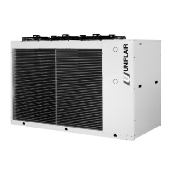
AIR-COOLED WATER CHILLERS
00182 - 00202 - 00232 - 00252 - 00302 - 00403 - 00504
AIR-COOLED HEAT PUMPS
00182 - 00202 - 00232 - 00252 - 00302 - 00403 - 00504
FREE COOLING CHILLERS
00182 - 00202 - 00232 - 00252 - 00302
ULTRA-LOW NOISE LEVEL FREE COOLING CHILLERS
00152 - 00182 - 00202 - 00232 - 00252 - 00302
INSTRUCTION MANUAL
GB
© UNIFLAIR 2000
ARA
.
A - D - L
H - P - Q
E
M
Versione: 1.4 - Data: 01.12.2000
Pag.: 48 - File: A-B-C-Ara14en
Advertisement
Table of Contents

Summary of Contents for Uniflair Aquaflair 00182
- Page 1 00182 - 00202 - 00232 - 00252 - 00302 ULTRA-LOW NOISE LEVEL FREE COOLING CHILLERS 00152 - 00182 - 00202 - 00232 - 00252 - 00302 INSTRUCTION MANUAL © UNIFLAIR 2000 Versione: 1.4 - Data: 01.12.2000 Pag.: 48 - File: A-B-C-Ara14en...
- Page 2 UNIFLAIR ITALIA S.r.l. Via dell’Industria, 10 35020 BRUGINE (Padova) Italy Tel. +39 (0)49 9713211 Fax. +39 (0)49 5806906 Internet: www.UNIFLAIR.com E-Mail: info@UNIFLAIR.com Release: Date: 01 - 12 – 2000 Checked by:...
-
Page 3: Table Of Contents
CONTENTS WARNINGS Page. 4 SYMBOLS USED SAFETY GENERAL DESCRIPTION Documentation included with the unit Available versions and accessories Data plate General description and intended use of the unit Access to main components Description of the main components of the unit Free cooling System - Free cooling Recovery of condensation heat INSTALLATION... -
Page 4: Warnings
This unit has been subjected to risk analysis under EC Directive 98/37/CEE (89/392/CEE). The technical solutions implemented during the design phase are described in the unit’s technical file. This equipment is manufactured to function safely for the purposes for which it was designed as long as the installation, operation and maintenance are carried out according to the instructions in this manual and on the labels attached to the unit. -
Page 5: Symbols Used
RISK SAFETY The new range of UNIFLAIR ARA water chillers and heat pumps features state-of-the-art technology to give maximum reliability, safety, quietness of operation and respect for the environment. RELIABILITY: Trouble-free operation of Uniflair precision chillers is ensured by rigorous production process controls under ISO 9001-certified quality procedures: •... -
Page 6: General Description
GENERAL DESCRIPTION DOCUMENTATION INCLUDED WITH THE UNIT Every ARA chiller is delivered complete with the following documentation: • ARA and microprocessor control instruction manuals • Unit installation diagrams • Diagrams of the refrigerant and hydraulic circuits of the unit • Electrical diagrams •... -
Page 7: Available Versions And Accessories
AVAILABLE VERSIONS AND ACCESSORIES ARA00152 (only M versions), ARA00182, ARA00202, ARA00232, ARA00252, Models ARA00302, ARA00403 (not supplied for E and M versions), ARA00504 (not supplied for E and M versions) Configurations A : Basic version: mechanical cooling with on-off condensation control D : Basic version with modulating condensation control L : Ultra low-noise version with modulating condensation control H : Heat pump with on-off condensation control... -
Page 8: Data Plate
DATA PLATE The chiller data plate is in the electrical panel and gives the following information: • Model of the unit • Serial number • Voltage, number of phases and power supply frequency for primary and auxiliary circuits • Current and power absorbed •... - Page 9 RESISTANCE TO THE ELEMENTS Uniflair chillers boast excellent corrosion resistance and are built to withstand the harshest of conditions. The structure is in galvanised steel sheet painter with polyester powder; all external fastenings are in stainless steel. LOW NOISE LEVELS Even the basic units have very low noise levels thanks to large exchange surfaces and low fan running speeds.
-
Page 10: Access To Main Components
ACCESS TO MAIN COMPONENTS COMPRESSOR HOUSING and lift panel A using the two front To access the compressor housing, remove the 8 fixing screws handles B . Removing panel A gives access to the compressor housing, the microprocessor control user terminal and to the optional high and low pressure manometers.. - Page 11 PUMP GROUP To access the optional pump group and the free cooling pump remove the six fixing screws 6 and remove panel D using front handle E . To avoid contact with the fan blades there is a further steel protection panel F , fixed with screws.
- Page 12 R22 and HFC-R407C (environment-friendly) refrigerants. Units for operation with R134a are available on special order from UNIFLAIR ITALIA Srl. In order to prevent the refrigerant fluid diluting the oil and creating foam when the unit is started all free cooling or heat pump ARA models are fitted with oil heaters which switch on automatically when the compressor stops.
- Page 13 CHILLED WATER PUMP GROUP (optional) The pump group for the circulation of chilled water is available in different configurations: - one pump (type “A”, “B” or “C”); - two pumps (one in stand-by); - one pump plus reservoir tank; - two pumps (one in stand-by) plus reservoir tank. The pumps, with 2-pole motors (2900 rpm), are fitted with the related connections, collectors and electrical panel (located in the main electrical panel housing).
- Page 14 FREE COOLING During normal chiller functioning, the water consumed is treated in the brazed plate heat exchanger. When the external air temperature drops to such a level as to allow water pre-cooling, the control activates a recirculation pump which sends the water to a finned pipe coil, mounted in front of the condenser. For the correct power supply of the thermostatic valve it is necessary to maintain the condensation pressure sufficiently high.
-
Page 15: Recovery Of Condensation Heat
Refrigerant Circuit Water Circuit (Inside unit) (Not supplied by Uniflair) Heat Recovery Diagram In order to ensure the correct functioning of the chillers avoid that the heat recovery plate exchanger D is powered by water which is too cold. For this reason use of a three way valve VM is strongly advised yet remains the responsibility of the installer (see diagram). -
Page 16: Installation
INSTALLATION GUIDE TRANSPORT AND MOVEMENT The symbols on the packaging conform to the ISO7000 standard and are explained below: SYMBOL MEANING SYMBOL MEANING FRAGILE: handle with care THIS SIDE shows orientation of the unit. PROTECT AGAINST TEMPERATURE LIMITS: the unit MOISTURE: the packaged unit must not be stored outside these must be stored in a dry place. -
Page 17: Receiving And Storing The Unit
RECEIVING AND STORING THE UNIT Every unit leaves the factory in perfect condition. Therefore please check the unit very carefully on delivery and notify the transport company immediately and in writing of any damage. Check that the load capacity of the floor is sufficient to support the weight of the unit. The unit must be located on a solid and flat surface. -
Page 18: Positioning The Unit - Working Space
Do not install the unit near the sea (minimum recommended distance 200m) or near sulphur springs. If the installation location is particularly harsh, contact the Uniflair Sales dept. for possible technical solutions. The optional rubber feet reduce the transmission of vibrations to the floor. - Page 19 HYDRAULIC CONNECTIONS (see also the enclosed installation drawings and hydraulic diagram) 1) CHECK that the section of the chilled water pipes and the power of the circulation pump fitted are sufficient. An inadequate water flow significantly reduces the cooling capacity of the unit. 2) CHECK the water intake/output directions.
-
Page 20: Low-Temperature Operation With Antifreeze Mixture
- 17 °C NOTES: (1) If it is necessary to produce liquid at less than -10°C, Uniflair Italia srl must be informed at the time of ordering. (2) The dimensions of the pump motors used in standard units permit a maximum glycol percentage of 30% IMPORTANT: insulate tubes and chilled water connections carefully to avoid the formation of frost. -
Page 21: Guide To Sizing Of The Expansion Tank
3 bar. In applications which require water side pressure higher than 3 bar the unit must not be fitted with the pump group. In this case all enquiries must be addressed to UNIFLAIR ITALIA before the... -
Page 22: Electrical Connections
The power supply cable is not provided by Uniflair; the installer must select and obtain the correct cable size. For short distances (<30 metres) the following cable sizes are recommended:... - Page 23 To switch the unit on and off or to change heat pump function between cooling and heating from a remote switch:: 5) CONNECT the remote ON/OFF switch to terminals 10 and 50 on the electrical panel; 6) CONNECT the remote SUMMER/WINTER selector to terminals 10 and 51. For remote alarm signalling (without a remote user terminal): 7) USE terminals 311 and 321 for the PUMP ALARM signal to protect the pump motors;...
-
Page 24: Remote Control, Local Networks And Supervision Systems
REMOTE CONTROL, LOCAL NETWORKS AND SUPERVISION SYSTEMS REMOTE CONTROL It is possible to use remote switches to turn the unit on and off and change function from cooling to heating, as shown on the unit’s electrical diagram and in the section START-UP AND TESTING CHECK LIST. The microprocessor control panel can also be remote: •... - Page 25 CONNECTION TO A SUPERVISION SYSTEM (units with mP20 control only) With the addition of a serial circuit, the microprocessor control enables chiller function to be controlled by a centralised supervision system. For the connection of the control to the supervision systems, an optional serial board enables opto-isolated interface with a standard RS422 network for the transmission of unit data at 1.2 kByte/s.
- Page 26 (Units with basic control – not supplied with free cooling versions) The control panel enable data exchange with a supervision system via RS485 serial connection. The optional connection cable must be ordered to be attached to the SERIAL socket on the I/O board. FITTING THE OPTIONAL RS485 BOARD pin 1: pin 2:...
-
Page 27: Check List For Start-Up And Testing
After installation and before start-up the following points should be checked. In the event of problems, consult the troubleshooting section in this manual or contact the technical assistance staff at UNIFLAIR CLOSE the general switch and arm the automatic switches IM1, IM2, e IM8;... - Page 28 SWITCHING ON THE CONTROL (Units with mP20 control only) Connect the power supply to the auxiliary circuit of the unit electrical panel (IM8); the control is activated as follows: - the yellow power LED on the circuit board switches on (see Layout of circuit board); - there is a short acoustic signal;...
-
Page 29: Programming And Regulation
PROGRAMMING AND REGULATION MICROPROCESSOR CONTROL INTRODUCTION The control system consists of a microprocessor base circuit fitted in the unit and a user interface which can be either local or remote. Sophisticated algorithms enable monitoring and protection of unit components and the user interface provides clear information on unit status and any current alarms. - Page 30 mP20 ADVANCED CONTROL This type of control, fitted where higher levels of sophistication are required, is intended for technological applications and enables independent control of all compressors. The control system regulation program, contained in the EPROM on the base circuit, is identified by an alphanumeric code, explained below. ARA --- v.
-
Page 31: Regulation Of Cooling Capacity
REGULATION OF COOLING CAPACITY The unit’s cooling capacity is regulated by activating the various cooling capacity steps, depending on the temperature measured by intake water sensor T1. CHILLER INTAKE EXPANSION TANK CHILLER OUTPUT RESERVOIR TANK PLATE EXCHANGER Refrigerant circuit diagram. Sensor T2 on the chiller output line interrupts compressor function when the temperature drops below the value set for risk of freezing. -
Page 32: Setting The Safety Devices
SETTING THE SAFETY DEVICES The function parameter values set on the microprocessor control are given in the enclosed instruction manual. The table below gives the settings of the safety devices; these are also on the data plate on the unit. Component Setting Differential... -
Page 33: Technical Data
TECHNICAL DATA ELECTRICAL CURRENT (Cooling only versions – heat pumps) COMPRESSOR COMPRESSOR FANS circuit 1 circuit 2 MODEL VOLTAGE No. FLA LRA No. FLA LRA No. 400V/3ph 11.4 0.28 0.87 00182 50Hz 400V/3ph 0.28 0.87 00202 50Hz 00232 400V/3ph 0.28 0.87 50Hz 400V/3ph 0.28 0.87... - Page 34 ELECTRICAL CURRENT (Free cooling version) COMPRESSOR COMPRESSOR FANS circuit 1 circuit 2 MODEL VOLTAGE No. FLA LRA No. FLA LRA No. 400V/3ph 11.4 11.4 0.30 1.37 00152 50Hz 400V/3ph 11.4 0.30 1.37 00182 50Hz 00202 400V/3ph 0.30 1.37 50Hz 400V/3ph 0.30 1.37 00232 50Hz...
- Page 35 ELECTRICAL CURRENT (Ultra-Low noise Free cooling versions) COMPRESSOR COMPRESSOR FANS circuit 1 circuit 2 MODEL VOLTAGE No. FLA LRA No. FLA LRA No. 400V/3ph 11.4 11.4 0.28 0.87 00152 50Hz 400V/3ph 11.4 0.28 0.87 00182 50Hz 00202 400V/3ph 0.28 0.87 50Hz 400V/3ph 0.28 0.87...
-
Page 36: Dimensions And Weights
DIMENSIONS AND WEIGHTS AQUAFLAIR chillers are developed in three side groups, with a fixed height and depth and variable width. The weight of the unit is variable in accordance to the configuration of the pump group, the reservoir tank and other internal accessories. - Page 37 ARA Versione base (“solo freddo”) ARA Basic version (“cooling only”) BASIC VERSION DATI TECNICI TECHNICAL DATA MODELLO 00182 00202 00232 MODEL Alimentazione V/ph/Hz 400 / 3 / 50 Power supply Refrigerante Refrigerant Potenzialità frigorifera nomin. (1) 44.1 51.6 59.5 Nominal cooling capacity (1) Potenza el.
-
Page 38: Ara Basic Version (Cooling Only)
ARA Versione base (“solo freddo”) ARA Basic version (“cooling only”) BASIC VERSION DATI TECNICI TECHNICAL DATA MODELLO 00252 00302 00403 00504 MODEL Alimentazione V/ph/Hz 400 / 3 / 50 Power supply Refrigerante Refrigerant Potenzialità frigorifera nomin. (1) 69.7 77.9 88.2 98.4 Nominal cooling capacity (1) Potenza el. - Page 39 ARA Versione free cooling ARA with free cooling function FREE COOLING DATI TECNICI TECHNICAL DATA MODELLO 00152 00182 00202 00232 MODEL Alimentazione V/ph/Hz 400 / 3 / 50 Power supply Refrigerante Refrigerant Potenza resa in free cooling (1) 28.1 29.3 36.1 Nom.
- Page 40 ARA Versione free cooling ARA with free cooling function FREE COOLING DATI TECNICI TECHNICAL DATA MODELLO 00252 00302 MODEL Alimentazione V/ph/Hz 400 / 3 / 50 Power supply Refrigerante Refrigerant Potenza resa in free cooling 37.8 38.3 Nominal cooling capacity (free cooling) Potenzialità...
-
Page 41: Problem Solving
PROBLEM SOLVING GUIDE TO PROBLEM SOLVING PROBLEM POSSIBLE CAUSE CHECK/CORRECTIVE ACTION THE CHILLER DOES NOT WORK The electrical panel has no power Check for mains power supply Check that the main switch is closed The microprocessor control circuit Check that the IM8 automatic board has no power supply auxiliary circuit switch is armed Check that the fuses are active... - Page 42 PROBLEM POSSIBLE CAUSE CHECK/CORRECTIVE ACTION High intake pressure Check the chilled water return HIGH OUTPUT PRESSURE OR temperature and the control set INTERVENTION OF HIGH values PRESSURE PRESSOSTAT The thermostatic valve is not set or Check that the superheating of the LOW OUTPUT PRESSURE OR defective thermostatic...
- Page 43 PROBLEM POSSIBLE CAUSE CHECK/CORRECTIVE ACTION One of the unit’s safety devices Check for alarms on the user THE COMPRESSOR DOES NOT has intervened terminal display WORK WHEN CALLED BY THE THERMOSTAT Short circuit protection has Check the cause of the short circuit intervened and change the fuses The LP pressostat or anti-freeze...
-
Page 44: Bleeding The Water Circuit
BLEEDING THE WATER CIRCUIT If there is air in the water circuit it can be bled using the valves: - on the chilled water intake connection - on the optional reservoir tank During the winter shutdown (cooling-only versions) or for special maintenance, it may be necessary to drain the water circuit. - Page 45 data plate and verify that liquid supercooling at the thermostatic intake is 3 to 5°C less than the condensation temperature on the manometer scale and that the superheating is between 4 and 7°C NOTE: when charging with R407C check the liquid supercooling value (3 to 5°C) and not the sight glass. IMPORTANT WARNINGS Check the type of refrigerant used on the unit data plate and on the compressor data plate.
-
Page 46: Maintenance And Cleaning
MAINTENANCE AND CLEANING All maintenance and cleaning operations must be carried out safely, following the instructions in this manual. To ensure the correct functioning of the unit it is advisable to check regularly that the heat exchanger coils, the metal filters and the protection grilles are clean. IMPORTANT WARNING Disconnect the unit from the electric power supply before accessing internal components. - Page 48 UNIFLAIR ITALIA S.r.l. Via dell’industria, 10 35020 BRUGINE (Padova) - Italy Tel. +39 (0)49 9713211 Internet: www.UNIFLAIR.com Fax +39 (0)49 5806906 E-mail: INFO@UNIFLAIR.com...
Need help?
Do you have a question about the Aquaflair 00182 and is the answer not in the manual?
Questions and answers