
Related Manuals for E-FLITE Taylorcraft 450 ARF


Summary of Contents for E-FLITE Taylorcraft 450 ARF
-
Page 1: Specifications
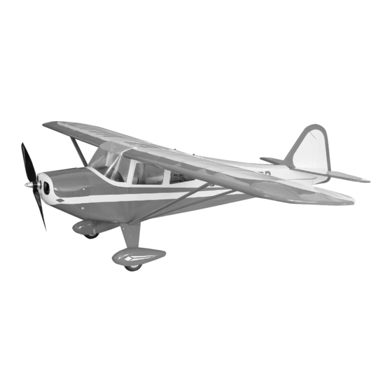
Taylorcraft 450 ARF Assembly Manual Specifications Wingspan: 46 in (1170mm) Length: 36 in (915mm) Wing Area: 370 sq in (23.87 sq dm) Weight w/o Battery: 29–31 oz (680–740 g) Weight w/ Battery: 24–26 oz (820–880 g) -
Page 2: Table Of Contents
Sport Outrunner Setup ............4 this outstanding ARF that boasts true-to-scale lines and is an High Power Setup..............4 absolute joy to fly. To keep the scale lines unspoiled, E-flite has Optional Accessories ............4 designed the Taylorcraft 450 with internal servo mounts that Required Tools and Adhesives .......... -
Page 3: Using The Manual
You will need to purchase 4 sub-micro 7.5 gram Remember to take your time and follow the directions. servos. If using your own transmitter, we recommend the use of a JR SPORT 6-channel UltraLite receiver and E-flite S75 Super ™ ®... -
Page 4: Important Information About Motor Selection
EFLA312B 40-Amp Brushless ESC 6-minute epoxy (HAN8000) 30-minute epoxy (HAN8002) APC12060E 12x6 Electric prop Canopy glue Thin CA EFLB21003S 11.1V 2100mAh 3-Cell Li-Po, 16 GA Medium CA Threadlock THP21003SPL 2100 mAh 3-Cell 11.1V Li-Po, 16GA E-flite Taylorcraft ARF Assembly Manual... -
Page 5: Notes Regarding Servos And Esc
Warranty Period in writing by Horizon before shipment. Horizon Hobby, Inc., (Horizon) warranties that the Products purchased (the “Product”) will be free from defects in materials and workmanship at the date of purchase by the Purchaser. E-flite Taylorcraft ARF Assembly Manual... -
Page 6: Damage Limits
To receive warranty service, you must include your original sales receipt verifying the proof-of-purchase date. Provided warranty conditions have been met, your Product will be repaired or replaced free of charge. Repair or replacement decisions are at the sole discretion of Horizon Hobby. E-flite Taylorcraft ARF Assembly Manual... -
Page 7: Non-Warranty Repairs
• Moisture causes damage to electronics. Avoid water exposure Champaign, Illinois 61822 to all equipment not specifically designed and protected for this purpose. Please call 877-504-0233 with any questions or concerns regarding this product or warranty. E-flite Taylorcraft ARF Assembly Manual... -
Page 8: Aileron Servo Installation
1. Use a pin drill and 1/16-inch (1.5mm) drill bit to enlarge the outer hole in a medium length servo arm. 4. Use side cutters to remove the remaining arm so it won't interfere with the operation of the servo. E-flite Taylorcraft ARF Assembly Manual... - Page 9 Attach the arm perpendicular to the servo. 6. Secure a 6-inch (152mm) servo extension to the servo lead using your favorite brand of servo wire keeper or tape. E-flite Taylorcraft ARF Assembly Manual...
- Page 10 9. Use a pencil to mark the location of the servo 11. Use a pin drill and 1/16-inch (1.5mm) drill bit to mounting tabs on the plate. drill the two mounting holes for the servo in the blocks. E-flite Taylorcraft ARF Assembly Manual...
- Page 11 #1 Phillips screwdriver. center of the wing. 13. Attach a weight to a piece of string. Lower the string into the opening in the wing for the servo. E-flite Taylorcraft ARF Assembly Manual...
- Page 12 2mm x 6mm sheet metal screws using a #1 Phillips screwdriver. 17. Use 6-minute epoxy to glue the aileron servo horn in position. Make sure to press the horn fully into the slot in the aileron. E-flite Taylorcraft ARF Assembly Manual...
- Page 13 19. Slide the opposite end of the pushrod through the connector. Use side cutters to remove any excess wire connector on the servo arm. extending beyond the connector. 22. Repeat Steps 1 though 21 for the remaining aileron servo and linkage. E-flite Taylorcraft ARF Assembly Manual...
-
Page 14: Joining The Wing Panels
1. Use a pencil to mark the wing panel and joiner so you can return the joiner into the orientation in which it was fit into the wing panels. 3. Use a pencil to draw a line on the joiner against the wing. E-flite Taylorcraft ARF Assembly Manual... - Page 15 7. Apply epoxy inside the opening in the wing as well. 5. Fit the two panels together. They should fit tight against each other with no gaps. E-flite Taylorcraft ARF Assembly Manual...
- Page 16 They will slide in the wing until they are flush with the back side of the wing center section. 11. Lightly score the wing bolt brace so it can bend to conform to the dihedral in the wing when installed. E-flite Taylorcraft ARF Assembly Manual...
- Page 17 A soldering iron of hot knife can be the pen. used as an option, reducing the chances of cutting into the wood. E-flite Taylorcraft ARF Assembly Manual...
- Page 18 16. Use medium CA to glue the brace to the wing. Hold the brace tightly against the wing until the CA cures. 15. Use a paper towel and rubbing alcohol to remove the lines drawn on the wing. E-flite Taylorcraft ARF Assembly Manual...
-
Page 19: Tail Installation
Note: You will want the slot for the elevator to be on the right side of the vertical fin and rudder during the next step. E-flite Taylorcraft ARF Assembly Manual... - Page 20 4. Trace the outline of the fuselage on the bottom of the on the fin will extend slightly, locking into the slot in the stabilizer using a felt-tipped pen. fuselage. Make sure the fin is straight with the center line of the fuselage. E-flite Taylorcraft ARF Assembly Manual...
- Page 21 Again, be careful fuselage. not to cut into the stabilizer. 7. Secure the wing to the fuselage using two 4-40 x 1-inch socket head screws and two #4 washers. E-flite Taylorcraft ARF Assembly Manual...
- Page 22 If not, lightly sand the fuselage where the rest. Place the tail assembly on the fuselage and double- stabilizer rests to correct any alignment issues. check all alignments made. Allow the epoxy to fully cure before moving your airframe. Align Parallel E-flite Taylorcraft ARF Assembly Manual...
-
Page 23: Servo Installation
3. Insert the control horn into the slot in the rudder. Hint: Use low-tack masking tape to hold the rudder and elevator centered while installing the servos. E-flite Taylorcraft ARF Assembly Manual... - Page 24 Use side cutters to trim the pushrod wire to the correct length. 5. Apply a few drops of medium CA to the junction between the control horn and backplate to secure it in place. E-flite Taylorcraft ARF Assembly Manual...
-
Page 25: Landing Gear Installation
1. Attach the landing gear covers to the landing gear using four 2mm x 6mm machine screws. The front edge of the covers will line up with the front edge of the landing gear when installed correctly. E-flite Taylorcraft ARF Assembly Manual... - Page 26 Check that the wheel can spin freely on the screw. 4. Pass the screw into the lower hole in the landing gear. Secure the wheel using a 4-40 locknut. E-flite Taylorcraft ARF Assembly Manual...
- Page 27 2mm x 6mm sheet metal screw. 7. Use a felt-tipped pen to mark the location for the wheel pant screw. 5. Repeat Steps 6 through 9 to install the remaining wheel pant. E-flite Taylorcraft ARF Assembly Manual...
-
Page 28: Motor And Cowling Installation
2. Attach the motor to the motor box using four 4-40 x firewall. 3/8-inch socket head screws. Use threadlock to prevent the screws from vibrating loose during flight. E-flite Taylorcraft ARF Assembly Manual... - Page 29 Note: Never check the motor rotation on the bench with the propeller installed. The plane could move and cause serious injury. Always check the motor without the propeller to avoid injury. E-flite Taylorcraft ARF Assembly Manual...
- Page 30 An unbalanced propeller may strip the gears or cause poor flight characteristics. Note: If it is necessary to enlarge the hole in the propeller, make sure to check the balance of the propeller afterwards. E-flite Taylorcraft ARF Assembly Manual...
- Page 31 12. Apply 2–3 drops of thin CA to each of the holes in mounting screws. the fuselage to harden the surrounding wood. Note: Ensure the painted stripe on the cowl lines up with the stripe on the fuselage E-flite Taylorcraft ARF Assembly Manual...
-
Page 32: Final Radio Installation
Plug a Y-harness to the connector for the ailerons. 2. Use hook and loop tape to secure the receiver under the radio tray inside the fuselage. 14. Secure the propeller to the motor. E-flite Taylorcraft ARF Assembly Manual... - Page 33 3. Remove the battery hatch from the fuselage. 4. Install the battery in the fuselage using the 8-inch (204mm) hook and loop strap. Replace the battery door once the battery has been installed. E-flite Taylorcraft ARF Assembly Manual...
-
Page 34: Window And Strut Installation
3. Use canopy glue to glue the windshield to the fuselage. Use low-tack masking tape to hold the windshield in position until the glue fully cures. E-flite Taylorcraft ARF Assembly Manual... - Page 35 They can be turned over (top to bottom) if they do not align with the holes in the wing and fuselage. Secure the strut to the fuselage using a 2mm x 8mm sheet metal screw. E-flite Taylorcraft ARF Assembly Manual...
-
Page 36: Control Throws
High Rate: 7/8-inch (22mm) with 25% Expo (Up/Down) Rudder -inch (38mm) (Left/Right) These are general guidelines measured from our own flight tests. You can experiment with higher rates to match your preferred style of flying. E-flite Taylorcraft ARF Assembly Manual... -
Page 37: Center Of Gravity
Use the 2 -inch (60mm) CG for sport/scale flying and the inch (73mm) CG for aerobatic flying. After the first flights, the CG position can be adjusted for your personal preference. E-flite Taylorcraft ARF Assembly Manual... -
Page 38: Preflight
Check all the control horns, servo horns, and clevises to make sure they are secure and in good condition. Replace any items that would be considered questionable. Failure of any of these components in flight would mean the loss of your aircraft. E-flite Taylorcraft ARF Assembly Manual... -
Page 39: 2007 Official Ama National Model Aircraft Safety Code
Only personnel involved with flying the aircraft are allowed at or in front of the flight line. Intentional flying behind the flight line is prohibited. E-flite Taylorcraft ARF Assembly Manual... - Page 40 © 2007 Horizon Hobby, Inc. 4105 Fieldstone Road Champaign, Illinois 61822 (877) 504-0233 horizonhobby.com E-fliteRC.com 10870...
Need help?
Do you have a question about the Taylorcraft 450 ARF and is the answer not in the manual?
Questions and answers