Table of Contents
Advertisement
This publication, including photographs, illustrations and software, is under the
protection of international copyright laws, with all rights reserved. Neither this
user's guide, nor any of the material contained herein, may be reproduced without
the express written consent of the manufacturer.
The information in this document is subject to change without notice. The manufac-
turer makes no representations or warranties with respect to the contents hereof
and specifically disclaims any implied warranties of merchantability or fitness for
any particular purpose. Further, the manufacturer reserves the right to revise this
publication and to make changes from time to time in the content hereof without
obligation of the manufacturer to notify any person of such revision or changes.
Trademarks
IBM, VGA, and PS/2 are registered trademarks of International Business Ma-
chines.
MMX, Pentium, Pentium-II, Pentium-III, Celeron are registered trademarks of
Intel Corporation.
Microsoft, MS-DOS and Windows XP/Vista are registered trademarks of Microsoft
Corporation.
AMI is a trademark of American Megatrends Inc.
It has been acknowledged that other brands or product names in this manual are
trademarks or the properties of their respective owners.
Static Electricity Precautions
1. Don't take this motherboard and components out of their original static-
proof package until you are ready to install them.
2. While installing, please wear a grounded wrist strap if possible. If you
don't have a wrist strap, discharge static electricity by touching the bare
metal of the system chassis.
3. Carefully hold this motherboard by its edges. Do not touch those compo-
nents unless it is absolutely necessary. Put this motherboard on the top of
static-protection package with component side facing up while installing.
Pre-Installation Inspection
1. Inspect this motherboard whether there are any damages to components
and connectors on the board.
2. If you suspect this motherboard has been damaged, do not connect power
to the system. Contact your motherboard vendor about those damages.
Motherboard User's Guide
Copyright © 2009
All Rights Reserved
P47G Series,
i
V1.0
March 2009
Advertisement
Table of Contents

Related Manuals for PC Chips P47G Series


Summary of Contents for PC Chips P47G Series
-
Page 1: Static Electricity Precautions
1. Inspect this motherboard whether there are any damages to components and connectors on the board. 2. If you suspect this motherboard has been damaged, do not connect power to the system. Contact your motherboard vendor about those damages. Copyright © 2009 All Rights Reserved P47G Series, V1.0 March 2009... -
Page 2: Table Of Contents
Motherboard User’s Guide Table of Contents Trademark ......................i Static Electricity Precautions ..................i Pre-Installation Inspection ..................... i Chapter 1: Introduction ..................1 Key Features ........................1 Package Contents ......................4 Chapter 2: Motherboard Installation .............. 5 Motherboard Components .................... 6 I/O Ports .......................... - Page 3 Motherboard User’s Guide Notice: Owing to Microsoft’s certifying schedule is various to every supplier, we might have some drivers not certified yet by Microsoft. Therefore, it might happen under Windows XP that a dialogue box (shown as below) pop out warning you this software has not passed Windows Logo testing to verify its compatibility with Windows XP.
-
Page 4: Chapter 1 Introduction
Chapter 1: Introduction Chapter 1 Introduction ® ® This motherboard has a LGA775 socket for latest Intel Core 2 Duo/Pentium ® Dual-Core/Celeron 4xx Series processors with Front-Side Bus (FSB) speeds up to 1333/1066/800 MHz. It integrates the G31 Northbridge and ICH7 Southbridge that supports the Serial ATA interface for high-performance and mainstream desktop PCs;... - Page 5 Motherboard User’s Guide Chipset There are G31 Northbridge and ICH7 Southbridge in the chipsets in accordance with an innovative and scalable architecture with proven reliability and perfor- mance. ® High Performance Host Interface: Supports Intel • Core 2 Duo/ ® ®...
- Page 6 Chapter 1: Introduction Audio 5.1 Channel High Definition Audio Codec • • Exceeds Microsoft Windows Logo Program (WLP) Requirements ADCs support 44.1K/48K/96K/192KHz sample rate • • High Quality Differential CD input Power Support: Digital: 3.3V; Analog: 5.0V • Supports 10/100 Mbps Ethernet Transceiver •...
-
Page 7: Package Contents
Motherboard User’s Guide Package Contents Your motherboard package ships with the following items: The motherboard The User’s Guide One IDE drive ribbon cable The Software support CD Optional Accessories You can purchase the following optional accessories for this motherboard. The Extended USB module The Serial ATA cable The Serial ATA power cable Note: You can purchase your own optional accessories from the third party,... -
Page 8: Chapter 2 Motherboard Installation
Chapter 2: Motherboard Installation Chapter 2 Motherboard Installation To install this motherboard in a system, please follow these instructions in this chapter: Identify the motherboard components Install a CPU Install one or more system memory modules Make sure all jumpers and switches are set correctly Install this motherboard in a system chassis (case) Connect any extension brackets or cables to headers/connectors on the motherboard... -
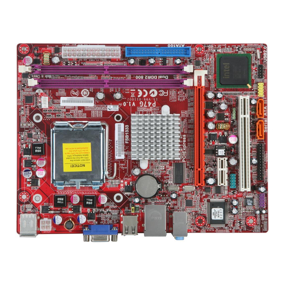
Page 9: Motherboard Components
Motherboard User’s Guide Motherboard Components LABEL COMPONENTS ® ™ LGA775 socket for Intel Core 2 Duo/ 1. CPU Socket ® ® Pentium Dual-Core/Celeron 4xx Series processors CPU cooling fan connector 2. CPU_FAN 240-pin DDR2 SDRAM slots 3. DDR2_1~2 4. ATX_POWER Standard 24-pin ATX power connector Primary IDE channel 5. -
Page 10: I/O Ports
Chapter 2: Motherboard Installation Ports The illustration below shows a side view of the built-in I/O ports on the motherboard. PS/2 Mouse Use the upper PS/2 port to connect a PS/2 pointing device. Use the low er PS/2 port to connect a PS/2 PS/2 Keyboard keyboard. -
Page 11: Installing The Processor
Motherboard User’s Guide Installing the Processor ® This motherboard has a LGA775 socket for the latest Intel Core 2 Duo/ ® ® Pentium Dual-Core/Celeron 4xx Series processors. When choosing a pro- cessor, consider the performance requirements of the system. Performance is based on the processor design, the clock speed and system bus frequency of the proces- sor, and the quantity of internal cache memory and external cache memory. -
Page 12: Installing Memory Modules
Chapter 2: Motherboard Installation E. Close the load plate • Slightly push down the load plate onto the tongue side, and hook the lever. • CPU is locked completely. F. Apply thermal grease on top of the CPU. G. Fasten the cooling fan supporting base onto the CPU socket on the motherboard. - Page 13 Motherboard User’s Guide Memory Module Installation Procedure These modules can be installed with up to 4 GB system memory. Refer to the following to install the memory module. Push down the latches on both sides of the DIMM socket. Align the memory module with the socket. There is a notch on the DIMM socket that you can install the DIMM module in the correct direction.
- Page 14 Chapter 2: Motherboard Installation Table A: DDR2 (memory module) QVL (Qualified Vendor List) The following DDR2 800/667 memory modules have been tested and qualified for use with this motherboard. Type Size Vendor Module Name Apacer 78.91G92.9K5 Micron MT4HTF6464AY-667E1 512 MB AL6E8E63J-6E1 Ramxel RML1520M38D6F-667...
- Page 15 Motherboard User’s Guide Type Size Vendor Module Name KVR800D2N5/512 1.8V 9905315- Kingston 019.A02LF 512 MB Micron MT8HTF6464AY-80ED4 Qimonda HYS72T64000HU-2.5-B A-DATA M2GVD6G3I41P0U1E5E AET760UD00-30DB97X Aeneon AET760UD00-25DC08X AU01GE800C5KBGC Apacer 78.01GAO.9K5 APOGEE AU1G082-800P000 Geil GEIL MILLENARY Hexon ELPT7AUDR-25M48 Infinity 04701G16CZ5U2G KVR800D2N5/1G 1.8V 9905316- 1 GB Kingston 054.A01LF Nanya...
-
Page 16: Jumper Settings
Chapter 2: Motherboard Installation Jumper Settings Connecting two pins with a jumper cap is SHORT; removing a jumper cap from these pins, OPEN. CLR_CMOS: Clear CMOS Jumper Use this jumper to clear the contents of the CMOS memory. You may need to clear the CMOS memory if the settings in the Setup Utility are incorrect and prevent your motherboard from operating. - Page 17 Motherboard User’s Guide KBMPWR: Rear USB PS/2 Power Select Jumper (for PS/2 S3 wakeup only) Function Jum per Setting Short Pins 1-2 KBMPWR 5VSB Short Pins 2-3 Notes: 1. Make sure the power supply provides enough SB5V voltage before selecting the SB5V function. 2.
-
Page 18: Install The Motherboard
Chapter 2: Motherboard Installation Install the Motherboard Install the motherboard in a system chassis (case). The board is a Micro ATX size motherboard. You can install this motherboard in an ATX case. Make sure your case has an I/O cover plate matching the ports on this motherboard. Install the motherboard in a case. -
Page 19: Connecting Optional Devices
Motherboard User’s Guide Connecting Optional Devices Refer to the following for information on connecting the motherboard’s optional devices: SPK: Speaker Header Connect the cable from the PC speaker to the SPK header on the motherboard. Signal Signal Signal COM: Onboard serial port header Connect a serial port extension bracket to this header to add a second serial port to your system. - Page 20 Chapter 2: Motherboard Installation F_AUDIO: Front Panel Audio Header This header allows the user to install auxiliary front-oriented microphone and line- out ports for easier access. Signal Signal PORT1L PORT1R PRESENCE# PORT2R Sense1_return SENSE_SEND PORT2L Sense2_return F_USB: Front panel USB Header The motherboard has four USB ports installed on the rear edge I/O port array.
-
Page 21: Install Other Devices
Motherboard User’s Guide Install Other Devices Install and connect any other devices in the system following the steps below. IDE Devices IDE devices include hard disk drives, high-density diskette drives, and CD-ROM or DVD-ROM drives, among others. The motherboard ships with an IDE cable that can support one or two IDE devices. If you connect two devices to a single cable, you must configure one of the drives as Master and one of the drives as Slave. -
Page 22: Expansion Slots
Chapter 2: Motherboard Installation Serial ATA Devices The Serial ATA (Advanced Technology Attachment) is the standard interface for the IDE hard drives, which is designed to overcome the design limitations while enabling the storage interface to scale with the growing media rate demands of PC platforms. - Page 23 Motherboard User’s Guide Follow the steps below to install an PCI Express/CNR/PCI expansion card. Locate the PCI Express, CNR or PCI slots on the motherboard. Remove the blanking plate of the slot from the system chassis. Install the edge connector of the expansion card into the slot. Ensure the edge connector is correctly seated in the slot.
-
Page 24: Chapter 3: Bios Setup Utility
Chapter 3: BIOS Setup Utility Chapter 3 BIOS Setup Utility Introduction The BIOS Setup Utility records settings and information of your computer, such as date and time, the type of hardware installed, and various configuration settings. Your computer applies the information to initialize all the components when boot- ing up and basic functions of coordination between system components. -
Page 25: Standard Cmos Setup Page
Motherboard User’s Guide Some options on the main menu page lead to tables of items with installed values that you can use cursor arrow keys to highlight one item, and press PgUp and PgDn keys to cycle through alternative values of that item. The other options on the main menu page lead to dialog boxes requiring your answer OK or Cancel by selecting the [OK] or [Cancel] key. - Page 26 Chapter 3: BIOS Setup Utility IDE BusMaster This item enables or disables the DMA under DOS mode. We recommend you to leave this item at the default value. IDE Devices Your computer has one IDE channel which can be installed with one or two devices (Master and Slave).
-
Page 27: Advanced Setup Page
Motherboard User’s Guide Advanced Setup Page This page sets up more advanced information about your system. Handle this page with caution. Any changes can affect the operation of your computer. CMOS Setup Utility – Copyright (C) 1985-2005, American Megatrends, Inc. Advanced Setup Help Item Thermal Management... - Page 28 Chapter 3: BIOS Setup Utility Boot Up NumLock Status This item determines if the NumLock key is active or inactive at system start-up time. APIC Mode This item allows you to enable or disable the APIC (Advanced Programmable Interrupt Controller) mode. APIC provides symmetric multi-processing (SMP) for systems, allowing support for up to 60 processors.
-
Page 29: Advanced Chipset Setup Page
Motherboard User’s Guide Advanced Chipset Setup Page This page sets up more advanced chipset information about your system. Handle this page with caution. Any changes can affect the operation of your computer. CMOS Setup Utility – Copyright (C) 1985-2005, American Megatrends, Inc. Advanced Chipset Setup Help Item DRAM Frequency... -
Page 30: Integrated Peripherals Page
Chapter 3: BIOS Setup Utility Integrated Peripherals Page This page sets up some parameters for peripheral devices connected to the system. CMOS Setup Utility – Copyright (C) 1985-2005, American Megatrends, Inc. Integrated Peripherals Help Item Onboard IDE Controller Enabled OnBoard SATA Controller Enhanced Onboard LAN Function Enabled... -
Page 31: Power Management Setup Page
Motherboard User’s Guide Parallel Port IRQ Use this item to assign IRQ to the parallel port. USB Functions Use this item to enable or disable the USB function. Legacy USB Support Use this item to enable or disable support for legacy USB devices. Setting to Auto allows the system to detect the presence of USB device at startup. -
Page 32: Pci/Pnp Setup Page
Chapter 3: BIOS Setup Utility PWRON After PWR-Fail This item enables your computer to automatically restart or return to its operating status. Resume By RING An input signal on the serial Ring Indicator (RI) line (in other words, an incoming call on the modem) awakens the system from a soft off state. -
Page 33: Pci Health Status Page
Motherboard User’s Guide Allocate IRQ to PCI VGA If this item is enabled, an IRQ will be assigned to the PCI VGA graphics system. You set this value to No to free up an IRQ. Press <Esc> to return to the main menu setting page. PCI Health Status Page This page helps you monitor the parameters for critical voltages, temperatures and fan speeds. -
Page 34: Frequency/Voltage Control Page
Chapter 3: BIOS Setup Utility Shutdown Temperature Enable you to set the maximum temperature the system can reach before powering down. System Component Characteristics These fields provide you with information about the system current operating status. • CPU Temperature • CPU Fan Speed •... -
Page 35: Load Default Settings
Motherboard User’s Guide Auto Detect DIMM/PCI Clk When this item is enabled, BIOS will disable the clock signal of free DIMM/PCI slots. Spread Spectrum If you enable spread spectrum, it can significantly reduce the EMI (Electro-Mag- netic Interference) generated by the system. Press <Esc>... -
Page 36: User Password Page
Chapter 3: BIOS Setup Utility User Password Page This page helps you set up some parameters for the hardware monitoring function of this motherboard. CMOS Setup Utility – Copyright (C) 1985-2005, American Megatrends, Inc. User Password User Password : Not Installed Help Item : Move Enter: Select +/-/: Value F10: Save... -
Page 37: Chapter 4 Software & Applications
Motherboard User’s Guide Chapter 4 Software & Applications Introduction This chapter describes the contents of the support CD-ROM that comes with the motherboard package. The support CD-ROM contains all useful software, necessary drivers and utility programs to properly run our products. More program information is available in a README file, located in the same directory as the software. - Page 38 Chapter 4: Software & Applications The Exit button closes the Auto Setup window. To run the program again, reinsert the CD-ROM disc in the drive; or click the CD-ROM driver from the Windows Explorer, and click the Setup icon. The Application button brings up a software menu. It shows the bundled software that this mainboard supports.
- Page 39 Motherboard User’s Guide The support software will automatically install. Once any of the installation procedures start, software is automatically installed in sequence. You need to follow the onscreen instructions, confirm commands and allow the computer to restart as few times as needed to complete installing what- ever software you selected.
- Page 40 Chapter 4: Software & Applications Follow these instructions to Disable Vista UAC function: Go to Control Panel. Select Classic View. Set User Account.
-
Page 41: Bundled Software Installation
Motherboard User’s Guide Select Turn User Account Control on or off and press Continue. Disable User Account Control (UAC) to help protect your computer item and press OK, then press Restart Now. Then you can restart your computer and continue to install drivers without running blocked programs.
Need help?
Do you have a question about the P47G Series and is the answer not in the manual?
Questions and answers