
Related Manuals for Potterton Sirius two WH


Summary of Contents for Potterton Sirius two WH
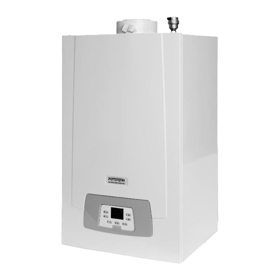
- Page 1 To be kept by the user November 2013 Sirius two WH 90 & 110 kW Instruction manual for users and fitters Working towards a cleaner future heating specialists...
-
Page 2: Table Of Contents
Dear Customer, Our company is confident our new product will meet all your requirements. Buying one of our products guarantees all your expec- tations: good performance combined with simple and rational use. Please do not put this booklet away without reading it first: it contains useful information for the correct and efficient use of your product. -
Page 3: Description Of Symbols
DESCRIPTION OF SYMBOLS WARNING Risk of damage to or malfunction of the appliance. Pay special attention to the warnings concerning dan- ger to people. DANGER OF BURNS Wait for the appliance to cool down before working on the parts exposed to heat. DANGER - HIGH VOLTAGE Live components - electrocution hazard. -
Page 4: General Precautions
GENERAL PRECAUTIONS This boiler has been designed to heat water to a temperature lower than boiling point at atmospheric pressure. It must be connec- ted to a central heating system and to a domestic hot water supply system according to its performance and power output. Before having the boiler installed by a qualified service engineer, make sure the following operations are performed: •... -
Page 5: Commissioning The Boiler
1. COMMISSIONING THE BOILER To light the boiler correctly, proceed as follows: • Check that the system pressure is correct (section 6); • Power the boiler; • Open the gas tap; • Select the required heating mode (section 1.2). During initial ignition, the burner may not ignite (causing the boiler to shut down) until any air in the gas pipes is vented. In this case, repeat the ignition procedure until gas reaches the burner. -
Page 6: Prolonged Shutdown. Frost Protection
2. PROLONGED SHUTDOWN. FROST PROTECTION Do not drain the whole system as filling up with water again could cause unnecessary and harmful scale to build up inside the boiler and the heating elements. If the boiler is not used during winter and is therefore exposed to the danger of frost, add some specific anti-freeze to the water in the system (e.g.: propylene glycol coupled with corrosion and scale inhibitors). -
Page 7: Filling The System
6. FILLING THE SYSTEM The pressure displayed on the pressure gauge has to be between 1 - 1.5 bar, with the system cold. If it is lower, turn the system filling tap installed by the fitter. IMPORTANT: open the tap very slowly in order to vent the air. The boiler is fitted with a hydraulic pressure switch which prevents the boiler from working if there is no water. -
Page 8: Instructions Prior To Installation
The boiler is supplied without the circulation pump. This component must be installed on the heating return to allow water to circu- late between the boiler and the low loss header and can be purchased off the shelf or supplied by POTTERTON COMMERCIAL as an accessory (modulating pump). -
Page 9: Installing The Flues
TABLE 1A ∆P (Pa) If the flue and air ducts installed are not supply by POTTERTON COMMERCIAL, make sure they are certitied for the type of use and WH 90 have a maximum pressure drop as indicated in the table to the side. -
Page 10: Electrical Connections
11. ELECTRICAL CONNECTIONS This machine is only electrically safe if it is correctly connected to an efficient earth system in compliance with current safety re- gulations. Connect the boiler to a 230V single-phase earthed power supply using the supplied three core cable, observing correct Live-Neutral polarity. -
Page 11: Connecting The Room Thermostat
11.1 CONNECTING THE ROOM THERMOSTAT The connections in terminal block M1 are in high voltage (230 V). Before making connections, make sure the appliance is disconnected from the power supply. Check the polarity: L (LIVE) - N (NEUTRAL). To connect the Room Thermostat to the boiler, proceed as de- scribed below: •... - Page 12 KEY TO FIGURE MENU Enduser Engineer Commissioning ALL MODIFIED PARAMETERS SHOULD BE NOTED DOWN IN THE TABLE AT THE END OF THIS MANUAL (page 31). The following procedure is used to access the four boiler pro- gramming menus: • from the main menu •...
-
Page 13: Outdoor System Management Modules
To connect this accessory, see figure to side (terminals 4-5) and the instructions supplied with the sensor. With the outdoor sensor connected, press buttons on the control panel to move the set climate curve Kt in parallel (see annex “SECTION” F and parameter P03 in the table in section 14). To increase room temperature press +, to decrease press -. SETTING THE “Kt”... -
Page 14: Special Functions
ALARM (LOCKOUT) 11.2.8 AGU 2.550 SIGNAL LAMP 230V 230 V Use the AGU 2.550 , already installed in the boiler, to send information from the boiler STATUS (RUN) (Boiler M1) as described below to a BMS panel. SIGNAL LAMP 230V ELECTRICAL CONNECTION Power supply (230V 50Hz AC) connected to the boiler terminal X1 (L-N) - Page 15 Factory ZONE 1 HEATING PARAMETERS Minimum Maximum (main zone) setting *Operating mode (0=Frost Protection, 1=Timed, 3=T.comfort) *Reduced ambient temperature °C *“Kt” curve slope *“Kt” curve drift - 4,5 *“Kt” curve adaptation (0=off) Flow temperature setpoint (minimum value) °C Flow temperature setpoint (maximum value) °C *Enable modulating temperature if set = “---”...
-
Page 16: Gas Valve Commissioning
MAINTENANCE 7045 Time after maintenance month 6704 View/Hide secondary fault internal code (0=no) BURNER CONTROL 9512 Required ignition speed 8000 9524 Required minimum operating speed (low speed) 8000 9529 Required maximum operating speed (high speed) 8000 BOILER CONTROL PANEL PARAMETERS Unit of measurement (1=bar, °C –... -
Page 17: Adjustment And Safety Devices
The functions performed by the adjustment and safety devices are only operative if the boiler is switched on. 17. PUMP CAPACITY/ HEAD The hydraulic pump, supplied as an accessory kit from POTTERTON COMMERCIAL, is a modulating pump. The purpose of the pump is to circulate the water between the boiler and the hydraulic separator. -
Page 18: Annual Servicing
18. ANNUAL SERVICING The service must be performed only by qualified and competent staff in accordance with the Gas safety, Installation and use re- gulations. In UK this person need to be approved by the Health and Safety Executive. To optimise boiler efficiency, carry out the following at the annual service: •... -
Page 19: Cleaning The Condensate Trap
BURNER IGNITION BURNER SURFACE 7,5 ±1 for model WH 90 ELECTRODE INSULATION 5,0 ±1 for model WH 110 FLAME DETECTION PROBE CG_2190 18.3 CLEANING THE CONDENSATE TRAP Unscrew the lower section of the water condense trap. • Clean the bottom of the trap by flushing it out with water. •... -
Page 20: Technical Specifications
19. TECHNICAL SPECIFICATIONS Model: SIRIUS TWO WH 90 WH 110 Category 2H3P Gas used Natural Gas and LPG G20 - G31 Rated heat input 87,4 104,9 Reduced heat input (G20) 11,7 Reduced heat input (G31) 12,5 11,7 Rated heat output 80/60 °C 85,0 102,0 Rated heat output 50/30 °C... - Page 21 7108686.02 (1-11/12)
- Page 22 Air/gas blend manifold Primary exchanger Coaxial flue connector Flue sensor Automatic air vent Ignition electrode NTC water heating sensor (flow and return) Safety overflow temperature thermostat Flame detection electrode Spark generator Venturi Pump Hydraulic Safety valve Boiler drain tap Pressure gauge Hydraulic Pressure Sensor Gas pressure switch Gas valve...
- Page 23 7108686.02 (1-11/12)
- Page 24 245,5 Ø Ø 90,5 90,5 354,5 245,5 Ø 184,5 245,5 G1-1/2 G1-1/2" G 1" G1-1/2 G1-1/2 7109986-01 7108686.02 (1-11/12)
- Page 25 7108686.02 (1-11/12)
- Page 26 Lmax = 10 m - Ø 110/160 mm Lmax = 9 m - Ø 110/160 mm Lmax = 10 m - Ø 110/160 mm Lmax = 8 m - Ø 110/160 mm Lmax = 9 m - Ø 110/160 mm 7108686.02 (1-11/12)
- Page 27 WH 90 WH 110 Q (l/h) WH 90 WH 110 Q (l/h) Q (l/h) 7108686.02 (1-11/12)
- Page 28 WEATHER COMPENSATION CURVE GRAPHS QAC34 7108686.02 (1-11/12)
- Page 29 AGU 2.550 CR_0349 AVS 75 CR_0349 7108686.02 (1-11/12)
- Page 30 SAFETY THERMOSTAT (Tmax=50°C - free contact) CG_2482 7108686.02 (1-11/12)
- Page 31 MODIFIED PARAMETERS VALUE NOTE 7108686.02 (1-11/12)
- Page 32 RS 33961 Baxi Commercial Sales: Technical: Wood Lane, Erdington, 0845 070 1056 0845 070 1057 Birmingham B24 9QP Email: potterton.commercial@baxicommercialdivision.com heating specialists www.pottertoncommercial.co.uk...
Need help?
Do you have a question about the Sirius two WH and is the answer not in the manual?
Questions and answers