Table of Contents
Advertisement
Installation & Service Instructions
About the Boiler
About Safety
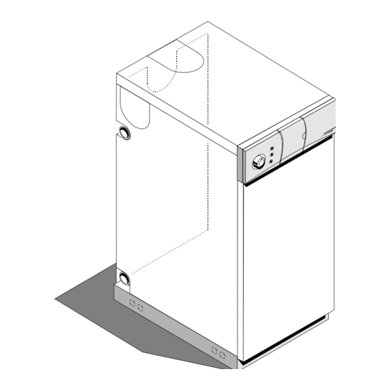
This is a Floor Standing, Horizontally Fired, Automatic Pressure Jet Oil Boiler.
The boiler can be flued conventionaly or with a kit as a balanced flue.
This boiler is for use with Kerosine or Gas Oil and for use in GB & IE.
Installation must be in accordance with the Installation & Service Instructions and the rules in
force.
Leave these instructions with the user for use on future calls.
Statesman
45/50, 50/70, 70/90, 90/110,
System, Flowsure, Flowsure +
Advertisement
Table of Contents

Related Manuals for Potterton Statesman 45/50


Summary of Contents for Potterton Statesman 45/50
- Page 1 Installation & Service Instructions Statesman 45/50, 50/70, 70/90, 90/110, System, Flowsure, Flowsure + About the Boiler This is a Floor Standing, Horizontally Fired, Automatic Pressure Jet Oil Boiler. The boiler can be flued conventionaly or with a kit as a balanced flue. This boiler is for use with Kerosine or Gas Oil and for use in GB &...
-
Page 2: Table Of Contents
Contents Section 1 - Technical Data..........4 Boiler Control Thermostat..........41 Health & Safety Information..........4 Thermostats - Flowsure/Flowsure+......42 Sealed System Components........6 Boiler Control Thermostat..........42 Control Panel Wiring Diagrams........10 Limit Thermostat............42 Technical Data............13 Pump Overrun Thermostat.........42 Boiler Dimensions & Clearances........14 Tank Limit Thermostat..........42 Flue Layouts...............15 DHW Overheat Thermostat........42 Heatstore Thermostat..........42... - Page 3 WARNING ! - this is about YOUR safety Safe use of Kerosines and Gas Oils Hazards These fuels give off a flammable vapour when heated even moderately. This vapour ignites easily, burns fiercely and can be explosive. Vapour can flow along at ground level and collect as an explosive mixture in drains, cellars etc. at considerable distances from open containers or spillages.
-
Page 4: Section 1 - Technical Data
1 - Technical Data • The Statesman boilers are horizontally fired, Flue Gas Sampling Point automatic pressure jet boilers. These boilers are intended for use on indirect central heating systems. To aid commissioning, a flue gas sampling point is Their use on direct systems is not recommended. built into the heat exchanger front access door. - Page 5 Statesman Top Flue Knockout Top Casing Side Flue Knockout Flue Outlet Thermostat Flange Pocket Programmer (Optional) Side Flue Knockout Indicator Lights Control Flow Outlet Thermostat Thermostat Pocket Front Access Door Boiler Shell Flue Gas Burner Sampling Air Inlet Side Burner Lead Cover Viewing Window Return Inlet...
-
Page 6: Sealed System Components
Statesman System, Flowsure & Flowsure+ pressure domestic hot water. The domestic hot water temperature can be increased by reducing the water flow rate at the tap (Flowsure) or adjusting Principal boiler components the hot water mixing valve to a higher setting (Flowsure+). - Page 7 Statesman Automatic Air Vent Conventional Flue Pump Pressure Relief Valve Thermostat Pocket Main Facia Panel Flow Control (22mm) Thermostat Thermostat Indictator Pocket Expansion Lights Programmer Vessel (Optional) Pressure and Burner Air Temperature Gauge Inlet Pipe Expansion Vessel Cradle Combustion Chamber Access Panel Lockout Combustion Chamber...
- Page 8 Statesman Certain Items Removed For Clarity Conventional Flue Flow Switch (Type 2) Manual Air Vent Automatic Air Vent Pressure Domestic Relief Valve Flow Service Boiler Switch Cock Supplied Thermostat (Type 1) Sleeve Pump Overrun Cold Water Pocket Feed (15mm) 3 bar D.H.W.
- Page 9 Flow Flow Switch D.H.W. Switch (Type 2) Flow (Type 1) (15mm) Statesman NOT Supplied Cold Mixing Water Certain Items Removed For Clarity Valve Feed Conventional (15mm) Tank Limit Flue Automatic Domestic Thermostat Air Vent Service Pressure Pocket Cock Relief Valve Plate Heat Pump Overrun...
-
Page 10: Control Panel Wiring Diagrams
Pump Boiler Control Panel Link to be replaced with Wiring Diagram Tray Assembly room thermostat Statesman..... Boiler Stat. Mains Burner Colour Coding Lockout For The Wiring - Blue Limit Stat. br - Brown Overheat Terminal gy - Grey Block - Red bl - Black Terminal g/y - Green/Yellow... - Page 11 Fig. 6 Technical Data Part No. 5102478...
- Page 12 Fig. 7 Technical Data Part No. 5102478...
-
Page 13: Technical Data
Technical Data System Flowsure Model 45/50 50/70 70/90 90/110 Flowsure+ Btu/h Btu/h Btu/h Btu/h kW Btu/h Maximum Output 51,000 68,000 89,000 110,000 32 85,000 25 Minimum Output 44,000 51,000 68,000 89,000 68,000 20 Factory Set Output Kerosine 51,000 61,000 82,000 102,000 30 82,000 24 Gas Oil... -
Page 14: Boiler Dimensions & Clearances
Boiler Dimension & Clearances System Flowsure Flowsure+ Model 70/90 90/110 45/50, 50/70 Height Width Depth Centre of flue from rear Flue Diameter Height between connections Height of bottom connection Distance of conn. from wall 1" B.S.P 1" B.S.P 1" B.S.P 1"... -
Page 15: Flue Layouts
Flue Options: Low Level Horizontal High Level Horizontal High Level Vertical Flue Kits 1, 2, 5, & 6 Flue Kits 3, 5, 6, 7, & 8 Flue Kits 3, 4, 5, 6, 9 & 10 Suitable for all Models Suitable for all Models Suitable for all Models (System, Flowsure &... -
Page 16: Section 2 - Pre-Installation Requirements
2 - Pre-Installation Requirements As with all building services, the oil fired systems have to be installed so as to ensure safe and efficient operation. The following notes provide a guide to current best practice. It is important that documents relating to Building Regulations and Standards are studied. -
Page 17: Chimneys/Flues
central heating systems for domestic premises. • BS 7074: Pt.1:1989 Application, selection and installation of expansion vessels and ancillary equipment for sealed systems. • BS 7671 Requirements for electrical installations. IEE wiring regulations 16th edition. • Control of pollution (oil) regulations. •... -
Page 18: Combustion & Ventilation Air Requirements
Internal Flues c) For the satisfactory operation of any draught break or stabilizer which may be fitted. The exposed flue pipe between the boiler flue off-take and the chimney proper (either internally or externally) Air for Combustion must not be of asbestos. Vitreous Cast Iron, Steel or similar materials should be used. -
Page 19: Balanced & Low Level Terminal Clearances
Extract Fans Draught Breaks If the room in which the appliance is located also has an When an appliance with a draught break is fitted in a room extract fan the performance of the appliance must be add 550mm /kW to the free area of the combustion air unaffected when the fan is running with all doors and inlet. - Page 20 Table Showing the Balanced Flue Clearance Dimensions Building Regulations England & Wales 1991 Scotland 1990 Balanced* 1500 Low Level* 1000 1000 1500 1000 Northern Ireland 1990 British Standard BS 5410 Part 1 1997 1200 1500 Fig. 13 * Where the terminal is within 1 metre of any plastic material, such material should be protected from the effects of combustion products.
-
Page 21: Oil Tanks & Layouts
Tank Support Adequate safety may be achieved in a number of ways, for example: Steel tanks are normally supported on masonry piers. These have to maintain the tank at a sufficient height to a) Protecting the tank by a physical barrier or isolating enable access to be gained for painting. - Page 22 Storage Requirements and Tank Sizes end of the vent is fitted with a return bend and an open wire mesh balloon. Tanks are available in a wide variety of sizes and capacities. For boilers of up to 13 kW (45,000 Btu/h) A mushroom type vent may be fitted provided its free tanks with a capacity of 1200 litres (250 gallons) are area is at least equal to the cross sectional area of the...
-
Page 23: Floor Temperatures
appliances with pressure jet burners by means of the building in the event of a fire starting up within the a single pipe need to be positioned so that they will boiler. apply the 300 mm minimum required head of oil to the burner when the fuel level is at its lowest point. - Page 24 The appliances incorporate a circulating pump, no other pump is required. The appliances will operate satisfactory on a two pipe small bore or micro bore system using thermostatically controlled radiator valves. When employing a central heating system where primary water flow may be prevented during a pump overrun situation (i.e.
- Page 25 The automatic air vent automatically expels any air- Flowsure and Flowsure+ released from the water and thereby keeps the boiler fully charged. The final 600 mm of the mains cold water connection to the boiler should be made in copper tubing to BS Filling and Make-up Loop 2871 Pt 1, which is recommended for water carrying pipework and must be used for pipework carrying...
- Page 26 Single Pipe Supply System Max. Oil Level 4 metres Above Burner Fire Valve Shut Off Sensor Valve Filter Fire Valve Max. Head 4m Pump Fire Valve De Aeration Sensor Device Fire Valve Oil Tank Below or Level Isolating with Burner Valve Oil Supply Pump...
-
Page 27: Section 3 - Installation & Commissioning
3 - Installation & Commissioning Low Level Horizontal - Kits 1 & 2 With Extensions Low Level Horizontal - Kits 7, 8 & 12 With Extensions Kit 5 950mm Dress Plate (Inner Wall) Dress Plate (Outer Wall) Kits 7 & 8 Kits 7 &... -
Page 28: Conventional Flue
Installation & Commissioning It is possible to install the boiler without removing the casing sides but care should be taken not to damage the panels when connecting the water pipes. Fitting a Balanced Flue Refer to the Instructions supplied with the flue. Fitting a Conventional Flue Local Building Regulations and Bye Laws should be consulted for details of the chimney, use a 135°... -
Page 29: Fuel Pipes
Wiring Diagrams: Refer to wiring diagrams in Section 1 of these Instructions. The mains inlet plug is provided in the bag of fittings supplied. Note: A permanent live supply must be made, to allow the pump overrun device, as fitted to the Flowsure and Flowsure+, to operate correctly. - Page 30 Fig. 21 Installation & Commissioning Part No. 5102478...
- Page 31 Fig. 22 Installation & Commissioning Part No. 5102478...
- Page 32 Fig. 23 Installation & Commissioning Part No. 5102478...
- Page 33 Room Stat Or Programmable Stat. Detail With Room Stat/Frost Stat Frost Stat gy * Clock Electro-mech. Remove Link COLOUR CODING b = Blue br = Brown gy = Grey w = White y = Yellow Only o = Orange p = Pink g/y = Green/Yellow Fig.
-
Page 34: Water Connections
An Isolation Valve should be placed on the tank side System and Flowsure: of the filter, so that the oil supply can be isolated when Return connections are provided on each side of the servicing is required. boiler at low level. A flow connection is provided at high level at the top rear of the boiler. - Page 35 Fig. 25 Installation & Commissioning Part No. 5102478...
-
Page 36: Commissioning
Commissioning Continuous failure to light is almost certainly due to air remaining in the fuel supply. It is strongly recommended that the boiler/burner is 9. Start and stop the burner two or three times until commissioned by a qualified technician, preferably the flame cuts off sharply - this indicates any OFTEC trained and registered. - Page 37 4. Having completed the necessary water connections, If the pressure indicated on the pressure gauge is those connections not utilised should be plugged. greater than 2.5 bar when operating at the maximum 5. Check that the central heating system has been fully central heating temperature, an extra expansion vessel flushed out at installation using a flushing agent.
- Page 38 Models: 50/70, 70/90, System, Remove The 3 Retarders, Examine For Model: 45/50 Damage, Replace if Necessary Flowsure & Flowsure+ Front Access 90/110 has 6 Retarders Door Lift Out The Plate Baffle Plate With These Holes For Models: 50/70, 70/90 System, Boiler Shell Flowsure Remove...
-
Page 39: Section 4 - Servicing & Maintenance
4 - Servicing & Maintenance • If the balanced flue is dismantled for any reason and • Examine interior of boiler and if necessary clean. the flue seals disturbed, new seals must be fitted. Remove any loose debris from the combustion Refer to the Parts Catalogue for part numbers. -
Page 40: Replacement Of Parts
for more than one heating season, a replacement should be fitted. If a metal fine Sight microbic filter is fitted then this should be Gauge cleaned with kerosene. Ensure that the filter Isolating bowl is thoroughly cleaned out before Valve replacement. -
Page 41: Thermostats - Statesman & System
Replacement of Thermostats (Statesman & System) 1. Remove the front cover. 2. Pull off the temperature control knob. 3. If a clock is fitted un-clip from the facia and disconnect the plug at the back. On the System Lift Off The Remove boiler disconnect the rear electrical connecter. -
Page 42: Thermostats - Flowsure/Flowsure
Replacement of Thermostats Boiler Control Thermostat (Flowsure/Flowsure+) 1. Disconnect the electrical connections. 1. Remove the front and top covers. 2. Remove the clip and withdraw the sensor 2. Pull off the temperature control knob. from its pocket. 3. Un-clip the programmer assembly and push into the 3. -
Page 43: Pressure Relief Valve
Pressure Relief Valve 5. Un-clip the temperature/pressure gauge from its bracket, remove gauge, carefully withdrawing 1. Drain the boiler using the boiler drain point provided. sensor and bulb capillary tubes through bracket 2. Undo the compression fitting connecting the assembly. discharge pipe to the relief valve. -
Page 44: Dhw Hot Water Plate Heat Exchanger
Domestic Service Cock (Flowsure/Flowsure+) 7. Fit a new plate heat exchanger in reverse order, ensuring to replace any damaged fibre washers. 1. Close the mains water isolation valve to boiler. 2. Drain the residual water from the hot water Flowsure+: pipework. - Page 45 Fig. 31 Servicing & Maintenance Part No. 5102478...
- Page 46 Fig. 32 Servicing & Maintenance Part No. 5102478...
-
Page 47: Section 5 - Fault Finding
5 - Fault Finding SYMPTOM CHECK LIST ACTION Burner Does Not 1. Mains switched on Switch on Start, Motor Does 2. Fuse in switch Fit a fuse Not Run 3. Fuse blown Replace fuse 4. All external controls call for heat Set to call for heat 5. -
Page 48: Burner Starts, No Flame But Oil To Burner
SYMPTOM CHECK FOR ACTION Burner Starts, 1. Signs of fuel in boiler Check as for 2 to 8 below No Flame But 2. Correct combustion head settings Set correctly refer to Burner Oil To Burner Instructions 3. Electrodes clean and not damaged Clean 4. -
Page 49: Flame Established But Not Maintained
SYMPTOM CHECK FOR ACTION Flame Established 1. Air in fuel line Check for joints for increases of air rectify as necessary, bleed burner But Not and restart Maintained 2. Combustion settings incorrect Adjust settings and confirm by flue gas analysis 3. -
Page 50: Other Problems
SYMPTOM POSSIBLE CAUSE ACTION 13. Bad oil cut off Bleed air from pump or replace pump assembly 14. Dirt collecting on fan Remove burner and clean 15. Combustion products leaking Check all joints, replace suspect seals SYMPTOM POSSIBLE CAUSE ACTION 1. - Page 51 Notes Notes Part No. 5102478...
- Page 52 6 - Short Spares Drg. Description Model - see key Makers Part Ref. Number Boiler thermostat A, B, C, D, E, F, G 26009018 Thermostat knob A, B, C, D, E, F, G 26002014 Limit thermostat A, B, C, D, E, F, G 26009097 Mains inlet plug A, B, C, D, E, F, G...
-
Page 53: Section 6 - Spare Parts
(System Flowsure Flowsure +) 5 (90/110) (50/70 70/90) (90/110) Not Spared 3 bar 28 / 29 Fig. 33 Spare Parts Part No. 5102478... -
Page 54: Section 7 - Flue Kit Options
7 - Flue Kit Options Dress Plate KIT 1 Fasteners Pack Horizontal Low Level Telescopic Instructions (Inner Wall) 4 - wood screws (Short Wall) 100 - 275mm 4 - wall plugs Inner Seal Outer Seal Dress Plate (Outer Wall) Gasket KIT 2 Horizontal Low Level Telescopic Fasteners Pack... - Page 55 Kit 5 Kit 4 Horizontal and Vertical Vertical Flue Extension Through 950mm Inner Seal Roof Outer Seal Terminal Kit 6 Horizontal and Vertical Flue Extension Inner Seal 300mm Outer Seal Clamping Plate Kit 7 Horizontal High Level Telescopic (Short Wall) Inner Seal 100 - 275mm Outer Seal...
- Page 56 Brochure Hotline: Tel: 08706 060 623 The Internet: http://www.baxi.com http://www.potterton.co.uk http://www.oilboilers.co.uk Registered Office: Sceptre Way, Bamber Bridge, Preston. PR5 6AW. Registered No. 3879156 All descriptions and illustrations provided in this leaflet have been carefully prepared but we reserve the right to make changes and improvements in our products which may affect the accuracy of the information contained in this leaflet.
Need help?
Do you have a question about the Statesman 45/50 and is the answer not in the manual?
Questions and answers