
Related Manuals for Neumann.Berlin KH 310 A


Summary of Contents for Neumann.Berlin KH 310 A
- Page 1 KH 310 A KH 310 D Active Studio monitor Operating ManuaL georg neumann gmbh · Leipziger str. 112 · 10117 berLin · germany teL +49 (0)30 / 41 77 24-0 · fax -50 · headoffice@neumann.com · www.neumann.com...
-
Page 3: Table Of Contents
Contents Important safety instructions ..........2 The KH 310 studio monitor . -
Page 4: Important Safety Instructions
Important safety instructions Read these instructions. Keep these instructions. Always include these instructions when passing the product on to third parties. Heed all warnings. 4. Follow all instructions. Do not use this apparatus near water. 6. Only clean the product when it is not connected to the mains power supply. Clean only with a dry cloth. - Page 5 Danger due to WARNING high sound Danger of hearing damage due to sudden high sound pressure levels! pressure levels Audio signals that are present at switch-on of the product or that can be present during operation, can create sudden, very high sound pressure levels which can damage your hea- ring.
-
Page 6: The Kh 310 Studio Monitor
OB vans, and post production studios for tracking, mixing, and mastering. Package contents 1 KH 310 A “left” or KH 310 A “right” 1 KH 310 D “left” or KH 310 D “right” 3 Mains cables (European, UK and US versions) -
Page 7: Product Overview
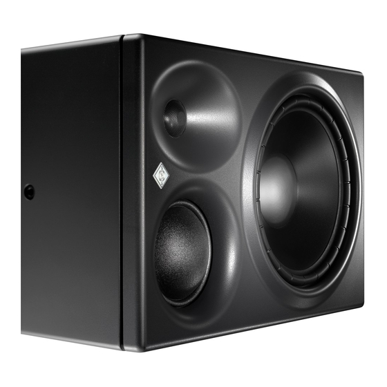
Product overview The KH 310 comes in two variants named “left” and “right” (see figure). It is also possi- ble to use a “left” in the “right” position, and vice versa. Both variants can also be used as a center loudspeaker. Information about positioning your KH 310 can be found from page 8. - Page 8 Back panel KH 310 A 5 ANALOG INPUT socket (XLR) 0 ACOUSTICAL CONTROLS switches 6 GROUND switch A Threaded inserts for Neumann mounting hard- (Connects/disconnects ground) ware 7 DISPLAY BRIGHTNESS switch B Handles with mounting holes (Dims the Neumann logo)
-
Page 9: Installing And Connecting The Kh 310
Installing and connecting the KH 310 CAUTION Danger of injury and material damage due to tipping/dropping of the product! If improperly mounted, the product and/or the mounting hardware (e.g. rack) can tip over or drop down. Always have the product mounted by a qualified specialist according to local, national and international regulations and standards. -
Page 10: Preparing The Room
To place the loudspeaker on a flat surface: Attach the supplied self-adhesive feet to the bottom of the cabinet. This reduces the risk of scratching the surface and acoustically isolates the loudspeaker from the surface. Preparing the room Arrange all acoustically relevant surfaces and objects symmetrically on either side of the listening axis of the room (left/right). - Page 11 0° -30° +30° Front Left Front Center Front Right -30° +30° Arranging the Copy the diagram “Installation angles” that can be found at the end of this operating manual. loudspeakers Place the diagram at the listening position or center of the listening area. Using a tape measure, place the loudspeakers at the same distance from the center of the dia- gram “Installation angles”.
- Page 12 If the loudspeakers cannot be placed at the same distance from the listening position: Compensate for distance differences > 1 cm ( ") by delaying closer loudspeakers by 30 µs/ cm (76 µs/inch). KH 310 D KH 310 D KH 310 D If you are using the KH 310 D: Use the DELAY rotary switches F to compensate for distance differences (see page 16).
-
Page 13: Connecting Audio Signals
12) or via an adapter (RCA-XLR) to the AES3 INPUT socket (XLR) J (see page 12) Connecting analog signals to the KH 310 A and the KH 310 D Only connect analog signals to the KH 310 A. Connecting Connect the left and right output of your analog audio source to the XLR input sockets of XLR cables... - Page 14 Connecting digital signals to the KH 310 D KH 310 D KH 310 D KH 310 D Connecting Connect the digital AES3 or S/P-DIF-output signal of your audio source to the AES3 AES3 cables INPUT socket H or J of the respective KH 310 D. See figure below. The KH 310 D loudspeaker only supports non-encoded AES3 and S/P-DIF signals.
- Page 15 KH 310 D KH 310 D KH 310 D Connecting multiple KH 310 D loudspeakers together Use the AES3 INPUT H and OUTPUT socket (BNC) I . T-pieces are not required (see figure below). Make an appropriate setting (“DIGITAL A” or “DIGITAL B”) on the SIGNAL SELECT rotary switch G.
-
Page 16: Connecting/Disconnecting The Kh 310 To/From The Mains Power Supply
Connecting/disconnecting the KH 310 to/from the mains power supply To connect the KH 310 to the mains power supply: Make sure that the on/off switch D is set to “0”. Connect the IEC connector of the supplied mains cable to the mains socket E. Power Source Connect the mains plug of the mains cable to a suitable wall socket. -
Page 17: Adjusting The Acoustical Level
The same loudspeaker installed in different positions in the same room may require different acoustical control settings. In a symmetrical installation, left/right pairs (front or back) will probably have the same acoustical control settings. Before using your loudspeaker system for the first time, calibrate the frequency response of the loudspeakers in the room in order to obtain the desired response. -
Page 18: Compensating For Video Delay (Lip Sync)
Set the OUTPUT LEVEL switch 9 and the INPUT GAIN control 8 of your loudspeakers so that the desired acoustic level is obtained. Recommended sound pressure levels: Application Sound pressure level Film 85 dB(C) Broadcast 79 to 83 dB(C) Music No defined reference levels If the Neumann logo flashes red, the loudspeaker‘s protection system has been activated. -
Page 19: Activating Ground Lift
KH 310 D KH 310 D KH 310 D Example Loudspeaker A listening distance: 1.50 m Loudspeaker B listening distance: 1.65 m Time-of-flight difference: 0.15 m So loudspeaker A should be delayed by the time equivalent of 0.15 m which is 0.436 ms (0.15 m / 3.44 cm x 0.1 ms). -
Page 20: Adjusting The Brightness Of The Neumann Logo
It might be possible to eliminate the noise by disconnecting the ground from the input signals (activating ground lift). To activate ground lift: Reconnect the signal cables and set the GROUND switch 6 to “LIFT”. This internally disconnects pin 1 of the ANALOG INPUT socket (XLR) 5 from the loudspeaker’s chassis ground (see diagram “Pin assignment of the XLR socket”... -
Page 21: Troubleshooting
Troubleshooting Problem Cause Solution The Neumann logo is off, no sound The KH 310’s internal Have the product checked by an autho- is heard from the KH 310 main fuse has blown. rized Neumann service partner. The Neumann logo is off or not The Neumann logo is Switch on the Neumann logo clearly visible, but sound is heard... - Page 22 16.2 l/28.3 l Weight KH 310 A: 13.0 kg (28 lbs 11 oz) KH 310 D: 13.1 kg (28 lbs 14 oz) These are the sample rates for which the delay setting value shown on the back panel is valid.
-
Page 23: Accessories
Drivers magnetically shielded bass, midrange, treble 210 mm (8 "), 75 mm (3"), 25 mm (1") Mounting points 2 x M8 thread on side panel, depth 25 mm (1"), Rear panel screws for attaching the LH 41 base plate Mounting holes in the handles Cabinet surface finish, Color Painted wood and polyurethane, Anthracite (RAL 7021) or other RAL color. -
Page 24: Manufacturer Declarations
Manufacturer Declarations Guarantee For the current terms and conditions of the product guarantee, please visit www.neumann.com. In compliance with the following requirements • WEEE (2012/19/EU) Please dispose of the product at the end of its operational lifetime by taking it to your local collection point or recycling center for such equipment. -
Page 25: System Block Diagram
System Block Diagram/System-Blockdiagramm/Synoptique Système/ Diagrama de Bloques del Sistema Pin assignment of the XLR socket/ Buchsenbelegung XLR/ KH 310 D only S/P-DIF can be received on the BNC Brochage de la prise XLR/ connectors with a suitable adapter Switched-mode Asignación de la hembra XLR/ BNC: AES3 Output Power Supply Power on... - Page 26 Free-Field Response | Freifeld-Frequenzgang | Réponse en Group Delay | Gruppenlaufzeit | Temps de propagation de champ libre | Respuesta en frecuencia en campo libre groupe | Retardo de grupo II | KH 310...
- Page 27 Harmonic Distortion at 90 dB SPL | Klirrfaktor bei 90 dB SPL Harmonic Distortion at 95 dB SPL | Klirrfaktor bei 95 dB SPL Distorsion harmonique à 90 dB SPL | Distorsión armónica total Distorsion harmonique à 95 dB SPL | Distorsión armónica total a 90 dB SPL a 95 dB SPL KH 310 | III...
- Page 28 Maximum SPL at 1 m (1 % and 3 %) | Maximaler SPL bei 1 m Acoustical Controls | Akustikregler | Effet des correcteurs de (1 % und 3 %) | Niveau SPL maximal, à 1 m (1 % et 3 %) | SPL compensation acoustiques | Regulador acústico máximo a 1 m (1 % y 3 %) IV | KH 310...
- Page 29 Cumulative Spectral Decay | Zerfalls spektrum | Décroissance spectrale cumulée | Caída espectral acumulada KH 310 | V...
- Page 30 Horizontal Directivity Plot | Horizontales Abstrahlverhalten Directivité horizontale | Directividad horizontal -24,0--21,0 -21,0--18,0 -18,0--15,0 -15,0--12,0 -12,0--9,0 -9,0--6,0 -6,0--3,0 -3,0-0,0 0,0-3,0 Angle (°) Frequency (Hz) VI | KH 310...
- Page 31 Vertical Directivity Plot | Vertikales Abstrahlverhalten Directivité verticale | Directividad vertical -24,0--21,0 -21,0--18,0 -18,0--15,0 -15,0--12,0 -12,0--9,0 -9,0--6,0 -6,0--3,0 -3,0-0,0 0,0-3,0 Angle (°) Frequency (Hz) KH 310 | VII...
-
Page 32: Installation Angles
Installation angles/Aufstellwinkel/Angles d�installation/Ángulos de colocación 22.5° 22.5° ° ° ° ° ° ° ° ° ° ° ° ° ° ° ° ° ° ° ° ° ° ° ° ° ° ° ° ° ° ° ° ° VIII | KH 310... -
Page 33: Delay Lookup Table
Digital Delay Lookup Table/Digital Delay Lookup Table/ Digital Delay Lookup Table/Digital Delay Lookup Table Switch 1 (25.6 ms) Switch 2 (1.6 ms) Position Time [ms] Distance [m] Distance [Imperial] Frames Time [ms] Distance [m] Distance [Imperial] Frames [feet] [inches] 50 Hz 60 Hz [feet] [inches]... - Page 34 Digital Delay Lookup Table/Digital Delay Lookup Table/ Digital Delay Lookup Table/Digital Delay Lookup Table Switch 3 (0.1 ms) Position Time [ms] Distance [m] Distance [Imperial] Frames [feet] [inches] 50 Hz 60 Hz 0.000 0.034 0.069 0.103 0.138 0.172 0.206 0.241 0.275 0.310 0.344...
- Page 35 03/15 · 554654/A02...
Need help?
Do you have a question about the KH 310 A and is the answer not in the manual?
Questions and answers