
Subscribe to Our Youtube Channel
Related Manuals for Neumann.Berlin KH 420


Summary of Contents for Neumann.Berlin KH 420
- Page 1 KH 420 Active Studio Monitor Operating ManuaL georg neumann gmbh · Leipziger str. 112 · 10117 berLin · germany teL +49 (0)30 / 41 77 24-0 · fax -50 · headoffice@neumann.com · www.neumann.com...
-
Page 3: Table Of Contents
..........13 Connecting/disconnecting the KH 420 to/from the mains power supply . -
Page 4: Important Safety Instructions
• If condensation has formed on the product, e.g. because it was moved from a cold environ- ment to a warm one, allow the product to acclimatize to room temperature before using it. • Do not overload wall outlets and extension cables as this may result in fire and electric shock. 2 | KH 420... - Page 5 • using the product within the operating conditions and limitations described in this opera- ting manual. “Improper use” means using the product other than as described in this operating manual, or under operating conditions which differ from those described herein. KH 420 | 3...
-
Page 6: The Kh 420 Studio Monitor
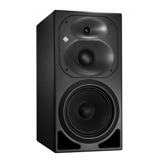
The KH 420 studio monitor Thank you for purchasing a Neumann studio monitor. The KH 420 features a Mathematically Modeled Dispersion™ Waveguide (MMD™), flexible acoustical controls, various input options and an extensive range of mounting hardware. This allows the loudspeaker to be used in diverse acoustical conditions, with any source equipment and in a wide variety of physical locations. -
Page 7: Product Overview
To refit the woofer ring, align the pegs with the holes and gently push until the woofer ring is fully inserted. KH 420 | 5... - Page 8 8 Threaded inserts for mounting hardware Remove inserted plastic plugs before attaching mounting hardware. 9 Accelerated Heat Tunneling™ cooling fins (AHT™) 6 | KH 420...
- Page 9 • PARAMETRIC EQUALIZER | FREQUENCY [Hz] Always have the DIM 1 installed by an autho- • PARAMETRIC EQUALIZER | FREQUENCY RANGE [Hz] rized Neumann service partner. G GROUND switch (Connects/disconnects ground) H ANALOG INPUT socket (XLR) KH 420 | 7...
-
Page 10: Installing And Connecting The Kh 420
Installing and connecting the KH 420 CAUTION Danger of injury and material damage due to tipping/dropping of the product! If improperly mounted, the product and/or the mounting hardware (e.g. rack) can tip over or drop down. Always have the product mounted by a qualified specialist according to local, national and international regulations and standards. - Page 11 Flush mounting The benefi ts of fl ush mounting are reduced cabinet edge diff raction (smoother midrange), the KH 420 increased bass driver loading (reduced bass distortion), and elimination of rear wall cancella- tions (fl atter bass response). KH 420 | 9...
-
Page 12: Preparing The Room
Similarly, avoid these distances from solid side walls or a solid ceiling. Respecting these positioning limitations reduces the chances of dips and peaks in the low frequency res- ponse (comb filtering) caused by strong reflections. 10 | KH 420... - Page 13 Place the diagram at the listening position or center of the listening area. Using a tape measure, place the loudspeakers at the same distance from the center of the dia- gram “Installation angles”. To ensure good imaging, do this at an accuracy of at least 1 cm "). KH 420 | 11...
- Page 14 (center, front left/right, surround left/right) ANSI/SMPTE 202M: 0°, ±22.5°, arrays to the surround left and to the surround right, plus optional subwoofer(s) • 7.1 systems: 0°, ±30°, ±90°, ±150°, plus optional subwoofer(s) (center, front left/right, side left/right, back left/right) 12 | KH 420...
-
Page 15: Connecting Audio Signals
Digital signals can only be connected when the DIM 1 module is installed. Connecting Connecting Connect the left and right output of your analog audio source to the XLR input sockets of the XLR cables XLR cables respective loudspeaker. Signal A Signal B Analog Source KH 420 | 13... - Page 16 Left Right Center Surround left Surround right Back left Back right A clock input is not required because loudspeakers are not audio sources and the converters are clocked to a very stable internally generated clock source. 14 | KH 420...
- Page 17 75 Ω termination. Set back panel switch to “DIGITAL A” Set back panel switch to “DIGITAL B” Subframe A - left signal Subframe B - right signal RCA, BNC or XLR Digital Source: AES 3 or S/P-DIF KH 420 | 15...
-
Page 18: Connecting/Disconnecting The Kh 420 To/From The Mains Power Supply
Connecting/disconnecting the KH 420 to/from the mains power supply To connect the KH 420 to the mains power supply: Make sure that the on/off switch E is set to “0”. Connect the IEC connector of the supplied mains cable to the mains socket D. -
Page 19: Configuring And Using The Kh 420
Conversely, switching off the loudspeaker immediately mutes the audio. Adjusting the frequency response When all its acoustical controls are set to 0 dB, the KH 420 loudspeaker is designed to have a flat frequency response in anechoic conditions. When the loudspeaker is installed in your monitoring environment, the response changes. - Page 20 -5.0 -3.0 -1.0 -7.5 -4.5 -2.0 for 0 dBu BASS TREBLE PARAMETRIC EQUALIZER 25-80 50-160 100-320 GAIN [dB] FREQUENCY FREQUENCY RANGE [Hz] Position 25-80 50-160 100-320 Max. input level 24 dBu (*18 dBu for analog delayed) 18 | KH 420...
-
Page 21: Adjusting The Acoustical Level
This is particularly true when setting the parametric equalizer. Adjusting the acoustical level On your KH 420 loudspeakers, set the OUTPUT LEVEL switch A to the lowest possible value of 94 dB SPL and the INPUT GAIN control B to −15 dB. -
Page 22: Compensating For Video Delay (Lip Sync)
Examples of sound pressure levels as a function of the input and output level of the KH 420: Input signal −20 (0.775 V) (0.775 V) (1.23 V) (77.5 mV) [dBu] INPUT GAIN control B −15 −4 −15 [dB] OUTPUT LEVEL switch A... -
Page 23: Activating Ground Lift
This internally disconnects pin 1 of the ANALOG INPUT socket (XLR) H from the loudspeaker’s chassis ground (see diagram “Pin assignment of the XLR socket” on page 14). For safety reasons, the electronics chassis ground is always connected to the mains power earth pin. KH 420 | 21... -
Page 24: Adjusting The Brightness Of The Neumann Logo
Solution The Neumann logo is off, no The KH 420’s internal main fuse Have the product checked by an sound is heard from the KH 420 has blown. authorized Neumann service partner. The Neumann logo is off or not The Neumann logo is switched off... -
Page 25: Specifications
Solution There is hum or buzz coming Bad cabling or ground loop in the Check all cabling to eliminate the from the KH 420 when the audio installation. cause of the problem, change from cable is connected. unbalanced to balanced cabling, or use the GROUND switch G (see page 21). - Page 26 ") External volume 93 l Weight 35.0 kg (77 lbs 3 oz) (+ 100 g (3 oz) when the DIM 1 is fitted) Drivers magnetically shielded bass, midrange, treble 250 mm (10"), 75 mm (3"), 25 mm (1") 24 | KH 420...
-
Page 27: Accessories
Safety: CAN/CSA-C22.2 No. 60065 Acoustical measurements, block diagram and pin assignment Additional technical data such as acoustical measurements, a block diagram of the KH 420 and the pin assignment of the XLR socket can be found at the end of this operating manual. -
Page 28: Manufacturer Declarations
This class B digital apparatus complies with the Canadian ICES-003. Changes or modifications made to this equipment not expressly approved by Neumann may void the FCC authoriza- tion to operate this equipment. 26 | KH 420... -
Page 29: System Block Diagram
Vous trouverez ci après les courbes correspondant aux mesures acoustiques effectuées en chambre sourde, à une distance de 1 mètre du moniteur. Las siguientes mediciones acústicas se han realizado bajo condiciones de baja reflexión a una distancia de 1 m. KH 420 | I... - Page 30 Free-Field Response | Freifeld-Frequenzgang | Réponse en Harmonic Distortion at 90 dB SPL | Klirrfaktor bei 90 dB SPL champ libre | Respuesta en frecuencia en campo libre Distorsion harmonique à 90 dB SPL | Distorsión armónica total a 90 dB SPL II | KH 420...
- Page 31 Harmonic Distortion at 100 dB SPL | Klirrfaktor bei 100 Distorsion harmonique à 95 dB SPL | Distorsión armónica total dB SPL | Distorsion harmonique à 100 dB SPL | Distorsión a 95 dB SPL armónica total a 100 dB SPL KH 420 | III...
- Page 32 1 m (1 %, 3 % und 10 %) | Niveau SPL maximal, à 1 m (1 %, 3 % et 10 %) | SPL máximo a 1 m (1 %, 3 % y 10 %) IV | KH 420...
- Page 33 Acoustical Controls | Akustikregler | Effet des correcteurs de Parametric Equalizer | Parametrischer Equalizer compensation acoustiques | Regulador acústico Égaliseur paramétrique | Ecualizador paramétrico KH 420 | V...
- Page 34 Cumulative Spectral Decay | Zerfalls spektrum | Décroissance spectrale cumulée | Caída espectral acumulada VI | KH 420...
- Page 35 Horizontal Directivity Plot (Vertical Cabinet Orientation) | Horizontales Abstrahlverhalten (Vertikale Gehäuseausrichtung) Directivité horizontale (Orientation verticale du coff ret) | Directividad horizontal (Orientación vertical del gabinete) -24 –-21 -21–-18 -18–-15 -15–-12 -12–-9 -9–-6 -6–-3 -3-0 Angle (°) Frequency (Hz) KH 420 | VII...
- Page 36 Vertical Directivity Plot (Vertical Cabinet Orientation) | Vertikales Abstrahlverhalten (Vertikale Gehäuseausrichtung) Directivité verticale (Orientation verticale du coff ret) | Directividad vertical (Orientación vertical del gabinete) -24 –-21 -21–-18 -18–-15 -15–-12 -12–-9 -9–-6 -6–-3 -3-0 Angle (°) Frequency (Hz) VIII | KH 420...
- Page 37 Horizontal Directivity Plot (Horizontal Cabinet Orientation) | Horizontales Abstrahlverhalten (Horizontale Gehäuseausrichtung) Directivité horizontale (Orientation horizontale du coff ret) | Directividad horizontal (Orientación horizontal del gabinete) -24 –-21 -21–-18 -18–-15 -15–-12 -12–-9 -9–-6 -6–-3 -3-0 Angle (°) Frequency (Hz) KH 420 | IX...
- Page 38 Vertical Directivity Plot (Horizontal Cabinet Orientation) | Vertikales Abstrahlverhalten (Horizontale Gehäuseausrichtung) Directivité verticale (Orientation horizontale du coff ret) | Directividad vertical (Orientación horizontal del gabinete) -24–-21 -21–-18 -18–-15 -15–-12 -12–-9 -9–-6 -6–-3 -3-0 Angle (°) Frequency (Hz) X | KH 420...
-
Page 39: Installation Angles
Installation angles/Aufstellwinkel/Angles d�installation/Ángulos de colocación 22.5° 22.5° ° ° ° ° ° ° ° ° ° ° ° ° ° ° ° ° ° ° ° ° ° ° ° ° ° ° ° ° ° ° ° ° KH 420 | XI... -
Page 40: Delay Lookup Table
3.853 204.8 70.451 12.8 4.403 230.4 79.258 14.4 4.954 256.0 88.064 16.0 5.504 281.6 96.870 17.6 6.054 307.2 105.677 19.2 6.605 332.8 114.483 10.0 20.8 7.155 358.4 123.290 10.8 22.4 7.706 384.0 132.096 11.5 24.0 8.256 XII | KH 420... - Page 41 Digital Delay Lookup Table/Digital Delay Lookup Table/ Digital Delay Lookup Table/Digital Delay Lookup Table Switch 3 (0.1 ms) Position Time [ms] Distance [m] Distance [Imperial] Frames [feet] [inches] 50 Hz 60 Hz 0.000 0.034 0.069 0.103 0.138 0.172 0.206 0.241 0.275 0.310 0.344 0.378 0.413 0.447 0.482 0.516 KH 420 | XIII...
- Page 42 04/14 · 554623/a01...
Need help?
Do you have a question about the KH 420 and is the answer not in the manual?
Questions and answers