Table of Contents
Advertisement
Series 601MM-1/2HP
Please read this manual and the enclosed safety materials carefully!
Fasten the manual near the garage door after installation.
The door WILL NOT CLOSE unless the Protector System
properly aligned.
Periodic checks of the opener are required to ensure safe operation.
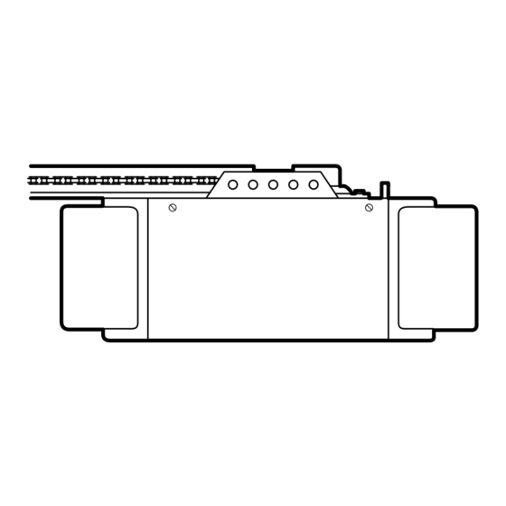
The model number label is located on the front end panel of your opener as
shown.
Garage Door Opener
For Residential Use Only
Series 651-2MM-1/2HP
Owner's Manual
Made exclusively for
Master Mechanic
Chicago, IL 60614
Complies with
UL 325
Regulations
effective
January 1, 1993.
Series 151MM-1/4HP
®
is connected and
®
Advertisement
Table of Contents

Subscribe to Our Youtube Channel
Related Manuals for Chamberlain Series 651-2MM-1/2HP


Summary of Contents for Chamberlain Series 651-2MM-1/2HP
- Page 1 Regulations effective ® January 1, 1993. Garage Door Opener For Residential Use Only Series 651-2MM-1/2HP Series 601MM-1/2HP Series 151MM-1/4HP Owner’s Manual Please read this manual and the enclosed safety materials carefully! Fasten the manual near the garage door after installation.
-
Page 2: Table Of Contents
Contents Page Contents Page A review of safety alert symbols........2 Install the lights and lenses ........19 You'll need tools............3 Attach manual release rope and handle....19 Safety information regarding garage door Electrical requirements..........20 locks and ropes............3 The Protector System ® ..........21 Testing your garage door for sticking, Install the safety reversing sensor .....22, 23 binding and balance...........3... -
Page 3: You'll Need Tools
You'll Need Tools During assembly, installation and adjustment of the opener, instructions will call for hand tools shown below. Pencil Carpenter's Level Hack Saw Tape Measure Wire Cutters Drill Claw Hammer 3/16", 5/16" and 5/32" Drill Bits Pliers 1/2" and 7/16" Sockets Stepladder Screwdriver Adjustable End Wrench... -
Page 4: Illustration Of Sectional Door Installation
SECTIONAL Door Installation Before you begin, survey your garage area to see whether any of the conditions below apply FINISHED CEILING to your installation. Support bracket & fastening hardware is required. Horizontal and vertical reinforcement See page 17. is needed for lightweight garage doors Slack in Chain Tension (fiberglass, steel, aluminum, door is Normal When... -
Page 5: Illustration Of One-Piece Door Installation
One-Piece Door without Track ONE-PIECE Door Installation Before you begin, survey your garage area to see whether any of the conditions below apply to your installation. Header Wall Closed Position Cable Pulley Bracket Trolley Cable Access Door Header Bracket T-rail Door Bracket Manual... -
Page 6: Carton Inventory
Carton Inventory Your garage door opener is packaged in one carton which contains all parts illustrated below. If anything is missing, carefully check the packing material. Parts may be "stuck" in the foam. Hardware for assembly and installation is shown on page 7. Model 651-2MM Only Model 651-2MM Only Models 601MM &151MM... -
Page 7: Hardware Inventory
Group all hardware found in all packages contained in the rail and opener cartons into the three kits illustrated below. Assembly Hardware Kit 41A2848 Hex Screw Washered Screw Carriage Bolt 5/16"-18x7/8" (3) 5/16"-18 (5) 5/16"-18x1/2" (2) Master Link (2) 1/4"-20x1/2" (12) (mounted in opener) Trolley Lock Nut... -
Page 8: Assembly Section: Pages
Hex Screws Assembly Section: Pages 8 – 11 5/16"-18x7/8" To avoid installation difficulties, do not run the garage door opener until instructed to do so. Assembly Step 1 Cable Pulley Bracket T-RAIL BACK Assemble the T-rail & (TO OPENER) Attach the Cable Pulley Bracket Square Carriage •... -
Page 9: Install Trolley
Hardware Shown Actual Size Assembly Step 2 Install the Trolley on the T-rail Shaft Inner Nut 5/16" Trolley Trolley Lock Washer • Attach the threaded shaft to the trolley with the 5/16" 5/16"-18 lock washer and nuts as shown. Lock Washer 5/16"... -
Page 10: Install Chain/Cable
Chain & Cable Cable Link Bar Pulley Push pins of master link bar through Chamberlain '92 cable loop and hole in front end of trolley. Push cap over pins and into 8/22/90 - 3/6/92 Install Chain & Cable notches. Slide clip-on spring over... -
Page 11: Tighten The Chain And Cable
Assembly Step 5 Tighten the Chain & Cable • Spin the inner nut and lock washer down the Lock threaded shaft, away from the trolley. Inner Nut Outer Nut Washer To Tighten • To tighten the chain, turn outer nut in the direction Outer Nut shown. -
Page 12: Installation Section: Pages
Installation Section: Pages 12 – 27 Installation Step 1 WARNING Determine Header Bracket Location Installation procedures vary according to garage If the header bracket is not rigidly fastened to a structural support on the header wall or door types. Follow the instructions which apply to ceiling, the safety reverse system may not your door. -
Page 13: One-Piece Door
ONE-PIECE Door Without Track Read the Safety Instructions on page 12. They also apply to doors without tracks. Unfinished Header Wall Ceiling Vertical Centerline • Close the door and mark the inside vertical centerline of Structural Supports your garage door. Extend the line onto the header wall above door. -
Page 14: Install The Header Bracket
You can attach the header bracket either to the Installation Step 2 wall above the garage door, or to the ceiling. Follow the instructions which will work best for Install the Header Bracket your particular requirements. Fasten the Header Bracket to the Wall •... -
Page 15: Attach The T-Rail To Header Bracket
Installation Step 3 Attach the T-rail to the Header Bracket • Position the opener on the garage floor below the header bracket. Use packing material as a Header Wall protective base. Header If the door spring is in the way you'll need help. Bracket Have someone hold the opener securely on a temporary support to allow the T-rail to clear... -
Page 16: Position The Opener
Installation Step 4 CAUTION Position the Opener To prevent damage to steel, aluminum, Follow instructions which apply to your door type fiberglass or glass panel doors, do not rest the as illustrated. opener on the door without using a 2x4. SECTIONAL Door &... -
Page 17: Hang The Opener
Installation Step 5 WARNING Hang the Opener The opener could fall and injure someone if it is not properly secured. Fasten the opener securely to structural supports of the garage. Two representative installations are shown. Yours may be different. Hanging brackets should be angled, Figure 1, to provide rigid support. -
Page 18: Install The Door Control
Installation Step 6 WARNING Install the Door Control Children operating or playing with a garage door opener can injure themselves or others. • Strip 1/4" of insulation from one end of the bell The garage door could close and cause wire;... -
Page 19: Install The Lights And Lenses
Installation Step 7 Install the Light(s) & the Lens(es) Install the Light(s) • Install a 75 watt maximum light bulb in (each) socket. The light(s) will turn ON and remain lit for (Model 651-2MM approximately 4-1/2 minutes when power is Lens Only) connected. -
Page 20: Electrical Requirements
Installation Step 9 WARNING Electrical Requirements To prevent electrocution or fire, installation and wiring must be in compliance with local electrical and building codes. Do NOT use an extension cord, 2-wire adapter, or change the plug in any way to make it fit To reduce the risk of electric shock, your garage your outlet. -
Page 21: The Protector System
The Protector System ® Information you'll need before you begin the installation of the safety reversing sensor. WARNING The safety reversing sensor must be connected Without a properly working safety reversing and aligned correctly before the garage door sensor, persons (particularly children) could opener will move in the down direction. -
Page 22: Install The Safety Reversing Sensor
Installation Step 10 Install the Safety Reversing Sensor Figures 2 and 3 show assembly of brackets and Figure 2 "C" wrap based on the recommended installation of Mounting Bracket the sensors on each side of the garage door as With Square Holes shown on page 21. - Page 23 • Incorrect wiring between sensors and opener. • Loosen the receiving eye wing nut to allow slight • An open wire (wire break). The Chamberlain Group, Inc. rotation of unit. Adjust sensor vertically and 2. If the sending eye indicator light glows steadily but Attaching Sensor to "C"...
-
Page 24: Fasten Door Bracket (Sectional Door)
Installation Step 11 CAUTION Fasten Door Bracket To prevent damage to steel, aluminum, Follow instructions which apply to your door type fiberglass or glass panel doors, always as illustrated below or on page 25. reinforce the inside of the door both vertically and horizontally with an angle iron. -
Page 25: Fasten Door Bracket (One-Piece Door)
All ONE-PIECE Door Installation Procedure Please read and comply with the warnings and reinforcement instructions on page 24. They apply to one-piece doors also. Header Wall – Finished Ceiling – 2x4 Support Header Horizontal and vertical Bracket Door Optional reinforcement is needed for Placement Bracket lightweight garage doors... -
Page 26: Connect Door Arm To Trolley (Sectional Door)
Installation Step 12 Connect Door Arm to Trolley Follow instructions which apply to your door type as illustrated below and on page 27. SECTIONAL Doors Only Make sure garage door is fully closed. Pull the manual release handle to disconnect the outer trolley from the inner trolley. -
Page 27: Connect Door Arm To Trolley (One-Piece Door)
All ONE-PIECE Doors Assemble the Door Arm: Door Bracket Ring • Fasten the straight and curved door arm sections Fastener Nuts together to the longest possible length (with a Lock 5/16"-18 Washers 2 or 3 hole overlap). 5/16" • With the door closed, connect the straight door Clevis Pin Straight arm section to the door bracket with a clevis pin. -
Page 28: Adjustment Section: Pages
Adjustment Section: Pages 28 – 30 Adjustment Step 1 WARNING Adjust the UP and DOWN Limits Improper adjustment of the travel limits will interfere with the proper operation of the safety reverse system. The door might not Limit adjustment settings regulate the points at reverse properly when required and could which the door will stop when moving up or down. -
Page 29: Force Adjustments
Adjustment Step 2 WARNING Adjust the Force Too much force on the door will interfere with the proper operation of the safety reverse system. The door might not reverse properly Force adjustment controls are located on the back when required and could seriously injure or kill panel of the opener. -
Page 30: Test The Protector System
Adjustment Step 3 WARNING Test the Protector System ® Without a properly working safety reversing sensor, persons (particularly children) could be seriously injured or killed if trapped by a • Press the remote control push button to open closing garage door. Repeat this test once a the door. -
Page 31: Operation Safety Instructions
IMPORTANT SAFETY INSTRUCTIONS WARNING WARNING To reduce the risk of severe injury or death to persons: 1. READ AND FOLLOW ALL INSTRUCTIONS. 2. Do not permit children either to operate or to play with the opener. Keep remote control in a location inaccessible to children. -
Page 32: Operation Of Your Opener
Operation of Your Opener Activate opener with any of the following devices: WARNING • The Remote Control. Hold push button down until the door starts to move. • The Door Control. Hold push bar or button down Weak or broken springs could allow an open until the door starts to move. -
Page 33: Receiver And Remote Control Programming
Receiver and Remote Control Programming To comply with FCC rules, adjustment or modifications of this receiver and/or transmitter are prohibited, except for changing the code setting or WARNING replacing the battery. THERE ARE NO OTHER USER SERVICEABLE PARTS. Children operating or playing with a garage door opener can injure themselves or others. -
Page 34: Having A Problem
Having a Problem? Situation Probable Cause & Solution 1. Does the opener have electric power? Plug a lamp into the outlet. If it doesn't light, The opener doesn't check the fuse box or the circuit breaker. (Some outlets are controlled by a wall switch.) operate from either the door control or 2. - Page 35 Having a Problem? (continued) Situation Probable Cause & Solution The door opens but 1. If the opener lights blink, check the safety reversing sensor. See page 23. won't close: 2. If the opener lights do not blink and it is a new installation, check the down force. See Adjustment Step 2, page 29.
-
Page 36: Repair Parts, Rail Assembly
Repair Parts Rail Assembly Parts PART DESCRIPTION 1A995 Master link kit 41A3489 Complete trolley assembly 183B112 Rail Braces (each) 183B111 T-rail – center sections (each) 183B113 T-rail – end sections (each) 41A3473 Chain and cable 41B2616 Cable pulley bracket assy. 83A4 Rail grease NOT SHOWN... -
Page 37: Repair Parts, Opener Assembly
Repair Parts Opener Assembly Parts Models 151MM Model 651-2MM Models 651-2MM & 601MM Model 651-2MM Models 601MM & 151MM (Down) LIMIT SWITCH ASSY. Contact Brown Wire Grey Wire Drive Gear Center Limit (Up) Yellow Contact Contact Wire PART KEY PART DESCRIPTION NO. -
Page 38: Accessories
Accessories Available For Your Opener 7702CB Outside Quick Release: 856MM Multi-Function Mini Remote Control: Required for a garage with NO With key ring & Velcro fastening access door. strip. 760MM Outside Keylock: Opens the garage door automatically 853MM Multi-Function Standard Size from outside when remote control is Remote Control: not handy. -
Page 39: Index
Index Access Door/Outside Quick Release Accessory....................4, 5 Chain Tension ..............................4, 5, 11 Electrical Safety Warnings........................2, 20, 31 Garage Door Testing for balance, binding and sticking....................3, 28, 31 Determining high point of travel: Sectional door..............................12 One-piece door ..............................13 Disabling existing locks............................3, 11 Force Controls Adjustment procedures.............................29 Problems that might require force adjustments ..................34, 35... -
Page 40: How To Order Repair Parts
MASTER MECHANIC/CHAMBERLAIN GARAGE DOOR OPENER ONE-YEAR LIMITED WARRANTY The Chamberlain Group, Inc. (“Seller”) warrants to the first retail purchaser of this product that it is free from defect in materials and/or workmanship for a period of one year from the date of purchase. The proper operation of this product is dependent on your compliance with the Owner’s Manual instructions regarding installation, operation, maintenance and testing.
Need help?
Do you have a question about the Series 651-2MM-1/2HP and is the answer not in the manual?
Questions and answers