Table of Contents
Advertisement
Quick Links
Advertisement
Table of Contents

Related Manuals for Focusrite RedNet MP8R


Summary of Contents for Focusrite RedNet MP8R
-
Page 1: User Guide
User Guide www.focusrite.com FFFA001146-01... -
Page 2: Important Safety Instructions
IMPORTANT SAFETY INSTRUCTIONS Read these instructions. Keep these instructions. Heed all warnings. Follow all instructions. Do not use this apparatus near water. Clean only with dry cloth. Do not block any ventilation openings. Install in accordance with the manufacturer’s instructions. Do not install near any heat sources such as radiators, heat registers, stoves, or other apparatus (including amplifiers) that produce heat. - Page 3 1. Do not modify this unit! This product, when installed as indicated in the instructions contained in this manual, meets FCC requirements. Modifications not expressly approved by Focusrite may void your authority, granted by the FCC, to use this product.
-
Page 4: Table Of Contents
RedNet MP8R Connections and Features ........ -
Page 5: About This User Guide
About this User Guide This User Guide applies only to the RedNet MP8R Mic Preamplifier. It provides information about installing a RedNet MP8R and how to connect it into your system. A RedNet System User Guide is also available from the RedNet product pages of the Focusrite website. -
Page 6: Introduction
INTRODUCTION Thank you for purchasing the Focusrite RedNet MP8R. RedNet MP8R is an 8-channel remote-controlled microphone preamplifier and A/D for the Dante audio-over-IP network. Specifically tailored for the road, live-sound and broadcast environments, each unit features network and power redundancy, rugged construction with latching connectors, remote control and remote monitoring. -
Page 7: Gain Compensated Split Outputs
Gain Compensated Split Outputs The RedNet MP8R is able to provide two outputs from each mic channel: one direct and a second automatically gain-compensated to deliver a constant level. This arrangement allows one engineer (FOH, say) to control the analogue mic gain without affecting the signal level being received by a second engineer on the network. -
Page 8: Installation Guide
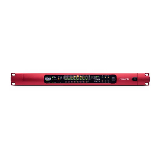
INSTALLATION GUIDE RedNet MP8R Connections and Features Front Panel AC Power Switch Switches power to both PSUs. Power Indicators: • PSU A – Illuminates when an AC input is applied and all DC outputs are present. • PSU B – Illuminates when an AC input is applied and all DC outputs are present. - Page 9 Front Panel . . . Continued OLED Display Indicates the currently selected channel’s network name and its gain value and if either Front Panel Lockout or Gain Compensation is active. Also changes to display local and network configuration settings when in INFO mode. See below. Local Control Buttons: •...
-
Page 10: Rear Panel
Latching etherCON connector for the Dante network. Use standard Cat 5e or Cat 6 network cable to connect to a local Ethernet switch to connect the RedNet MP8R to the RedNet network. Adjacent to each network socket are LEDs which illuminate to indicate a valid network connection plus network activity. -
Page 11: Power Connection
Power Connection IEC Power Cord Retaining Clips RedNet MP8R is supplied with two IEC power cord retaining clips. These prevent accidental disconnection of a power cord during use. When the unit is first installed, the retaining clips will need to be attached to the power input sockets on the rear panel. -
Page 12: Physical Characteristics
RedNet MP8R dimensions are illustrated in the diagram above. RedNet MP8R requires 1U of vertical rack space and at least 440mm of rack depth, to allow for cables. RedNet MP8R weighs 5.75 kg and for installations in a fixed environment (eg., a studio), the front-panel mounting screws will provide adequate support. -
Page 13: Rednet Mp8R Operation
If a Network Master is not present then the unit can be chosen as the Network Master by the user. Pull Up and Pull Down Operation RedNet MP8R is able to operate at a specified pull up or pull down percentage as selected in the Dante Controller application. -
Page 14: Other Rednet System Components
RedNet Control will reflect the status of the RedNet units present in the system, presenting an image representing each hardware unit. The illustration above shows the RedNet MP8R RedNet Control image. The signal level, gain and input function settings are indicated for each channel. -
Page 15: Id (Identification)
Notes: - The default is “Off” - 16 channels are available, allowing a maximum of 16 independent RedNet MP8R control paths - Two devices should not be set to the same MIDI channel - MIDI channel selection is saved with the computer, not the device. Therefore, when controlling the same unit from a different computer, the MIDI channel allocation may no longer be the same www.focusrite.com... -
Page 16: Appendix
APPENDIX Connector Pinouts Ethernet Connector Cat 6 Core Connector type: RJ-45 receptacle White + Orange Applies to: Ethernet (Dante) Orange White + Green Blue White + Blue Green White + Brown Brown XLR Connectors Connector type: XLR-3 receptacle Signal Applies to: Audio Input Screen Hot (+ve) -
Page 17: Performance And Specifications
PERFORMANCE AND SPECIFICATIONS Microphone Inputs Gain Range 0dB to 55dB in 1dB steps Electronically Balanced, Zin = 2.4kΩ/10kΩ (Switchable); Inputs default to 2.4kΩ when unit Type is unpowered Maximum Input Level 29dBu ±0.5; min gain with pad for 0dBFS, Rs = 150Ω Minimum Input Level -46dBu ±0.5;... - Page 18 Indicators Primary PSU (A) Green LED. Illuminates when an AC input is applied and all DC outputs are present. Secondary PSU (B) Green LED. Illuminates when an AC input is applied and all DC outputs are present. Green LED. Indicates that a network connection is present on primary port when in Primary network redundant mode.
-
Page 19: Focusrite Rednet Warranty And Service
In the event of a Manufacturing Defect becoming evident in a product within 12 months from the date of the original purchase Focusrite will ensure that the product is repaired or replaced free of charge. A Manufacturing Defect is defined as a defect in the performance of the product as described and published by Focusrite.
Need help?
Do you have a question about the RedNet MP8R and is the answer not in the manual?
Questions and answers