
Related Manuals for Focusrite ISA828 MkII


Summary of Contents for Focusrite ISA828 MkII
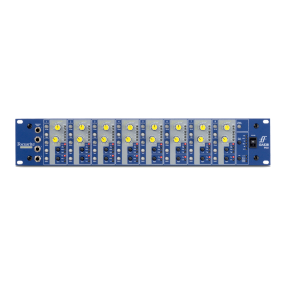
- Page 1 ISA828 MkII Eight channel mic pre and optional A-D card with Dante User Guide www.focusrite.com FA0145-04...
-
Page 2: Table Of Contents
........... . . Focusrite RedNet Warranty and Service... -
Page 3: About This User Guide
Mic pre to be added to a Dante network. If you feel that additional information might be of assistance, be sure to consult the site: https://pro.focusrite.com/technical-support, which contains a comprehensive collection of common technical support queries. Pro Tools® and Pro Tools | HD are trademarks or registered trademarks of Avid Technology, Inc. -
Page 4: Introduction
– a dial for calibration is provided on the rear panel. To maintain pristine Focusrite quality in the digital domain, an Analogue-to-Digital interface card may be fitted into the option slot on the rear panel. This provides access to a Dante network and features AES3, S/PDIF and ADAT signals. -
Page 5: Isa 828 Mkii Controls And Features
ISA 828 MKII CONTROLS AND FEATURES Front Panel LED meter Input channels 1–8 source Instrument inputs A-D option card: clock Power for channels 1–4 and sync selection switch Channel Controls Selects the high (30-60 dB) mic gain 10 dB stepped Mic/Line Gain switch range for the Gain switch Mic: 0-30 / 30-60 Line: -20 +10 Applies +48V phantom power to the... -
Page 6: Line Input
Channel Controls... Line Input The Gain switch sets the gain at between -20 dB and +10 dB in 10 dB steps. Continuous gain adjustment of up to 20 dB can be added using the Trim control. Instrument Input The Instrument inputs are accessed via standard 1/4” mono jacks on the front panel. The level is set using the Trim control only and is continuously adjustable from +10 dB to +40 dB. -
Page 7: Channel Meters
Channel Meters The LED meters can be switched to display signal level at two different audio paths, determined by the setting of the Meters Pre A-D switch on the front panel: • Meters Pre A-D switch OFF – LEDs show the signal at the channel output. This is the default setting and shows the level being sent to external recorders/outboard effects. -
Page 8: Rear Panel
Rear Panel Slot for A-D A-D external Analogue option card inputs 1-8 outputs 1-8 Mains Meter Trim Line input jacks Mic input XLRs inlet control AC Mains Inlet Standard IEC receptacle for AC mains. ISA 828 MkII features a ‘Universal’ PSU, enabling it to operate on any supply voltage between 100 V and 240 V AC. -
Page 9: A-D Option Card
A-D Option Card The optional ISA ADN8 A-D card can be retrofitted to an ISA 828 MkII at any time. Engineering experience is not required as the card can easily be installed by the user. Note that the ISA 828 MkII does not support the earlier ISA 8-Channel A-D card. Once fitted, configuration of the card is carried out over the network using either RedNet Control or the Dante Controller software application. -
Page 10: A-D Card Clock And Sync Switches
A-D Option Card... A-D Card Clock and Sync Switches Clock select Allows the user to select the internal sample frequency: 44.1kHz, 48kHz, 88.2kHz, 96kHz, 176.4kHz, or 192kHz. Allows the ISA ADN8 A-D card to be slaved to an external Word Clock source. Press the switch to toggle between standard and Dante clock. -
Page 11: Physical Characteristics
PHYSICAL CHARACTERISTICS 325.0mm / 12.8” 465.0mm / 18.3” 63.6mm / 2.5” Case dimensions are illustrated in the diagram above. ISA 828 MkII requires 2U of vertical rack space. Allow an additional 75mm of rack depth behind the unit to allow for cables. ISA 828 MkII weighs 7.05 kg and for installations in a fixed environment (eg., a studio rack), the front-panel rack mountings* will provide adequate support. -
Page 12: Appendices
APPENDICES 1. Connector Pinouts Mic Input Signal Connector: XLR-3 female Screen Hot (+ve) Cold (–ve) Line Input Signal Connector: Balanced (TRS) 1/4” Jack socket Hot (+ve) Ring Cold (–ve) Tip Ring Sleeve Sleeve Ground Instrument Input Signal Connector: Unbalanced (TS) 1/4” Jack socket Hot (+ve) Sleeve Ground... - Page 13 1. Connector Pinouts... ISA ADN8 Option Card: AES3 Outputs Signal Connector: DB25 female (AES59 digital) Out channels 7/8 Out channels 7/8 – Ground Out channels 5/6 Out channels 5/6 – Ground Out channels 3/4 Out channels 3/4 – Screw binding-posts use the standard UNC 4/40 thread Ground Out channels 1/2 Out channels 1/2...
-
Page 14: Preamp Input Impedance
Appendices... 2. Preamp Input Impedance A major element of the sound of a mic pre is related to the interaction between the specific microphone being used and the type of mic preamp interface technology it is connected to. The main area in which this interaction has an effect is the level and frequency response of the microphone, as follows: Level Professional microphones tend to have low output impedances and so more level can be achieved by... - Page 15 2. Pre Amp Impedance... impedance. Matching the mic preamp resistance to the microphone output impedance (eg., making a preamp input impedance 200 Ω to match a 200 Ω microphone) still reduces the microphone output and signal to noise ratio by 6 dB, which is undesirable. To minimise microphone loading, and to maximise signal to noise ratio, preamps have traditionally been designed to have an input impedance about ten times greater than the average microphone, around 1.2 kΩ...
-
Page 16: Pro Tools Interfacing
Appendices... 3. Pro Tools Interfacing • Analogue out to Pro Tools | HD ISA 828 MkII DB25 male – DB25 male 8ch analogue Red 16Line Pro Tools interface • Dante to Pro Tools | HD ISA 828 MkII Dante Network RedNet HD32R RJ45 –... -
Page 17: Performance And Specifications
PERFORMANCE AND SPECIFICATIONS Microphone Inputs All measurements taken at minimum gain, Z In: medium, unless otherwise stated. Measurements taken at the analogue outputs 0 to 30 dB or 30 to 60 dB (with ‘30-60’ switch enabled), in 10 dB steps, Gain Range plus 0 to 20 dB of continuous trim +7 dBu... - Page 18 Performance and Specifications . . . Connectivity Front panel Instrument inputs 4 x 1/4” mono jack Rear Panel Microphone inputs 8 x XLR-3 female Line level inputs 8 x 1/4” balanced jack Line level outputs 1 x DB25 female (AES59 Tascam Analogue) A-D inputs 1 x DB25 female (AES59 Tascam Analogue) Digital Card Slot...
-
Page 19: Focusrite Rednet Warranty And Service
In the event of a Manufacturing Defect becoming evident in a product within 12 months from the date of the original purchase Focusrite will ensure that the product is repaired or replaced free of charge. A Manufacturing Defect is defined as a defect in the performance of the product as described and published by Focusrite.
Need help?
Do you have a question about the ISA828 MkII and is the answer not in the manual?
Questions and answers