Sony DCR-TRV230E Service Manual
Digital video camera recorder
Hide thumbs
Also See for DCR-TRV230E:
- Service manual (75 pages) ,
- Operating instructions manual (216 pages) ,
- Operating instructions manual (216 pages)
Table of Contents
Advertisement
SERVICE MANUAL
SERVICE MANUAL
Ver 1.0 2001. 02
Video camera
recorder
System
Video recording system
2 rotary heads
Helical scaning system
Audio recording system
Rotary heads, PCM system
Quantization: 12 bits (Fs 32 kHz,
stereo 1, stereo 2), 16 bits
(Fs 48 kHz, stereo)
Video signal
PAL colour, CCIR standards
Recommended cassette
Hi8/Digital8 video cassette
Recording/playback time (using
90 min. Hi8 video cassette)
SP mode: 1 hour
LP mode: 1 hour and 30 minuites
Fastforward/rewind time (using
90 min. Hi8 video cassette)
Approx. 5 min.
Viewfinder
Electric Viewfinder, Monochrome
Image device
3 mm (1/6 type CCD)
(Charge Coupled Device)
Approx. 800 000 pixels
(Effective: Approx. 400 000 pixels)
Lens
Combined power zoom lens
Filter diameter 37 mm (1 1/2 in.)
25× (Optical), 700×* (Digital)
*800× (DCR-TRV235E/TRV430E)
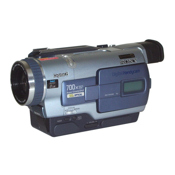
DCR-TRV230E/TRV235E/TRV325E/
TRV330E/TRV430E/TRV530E
Photo : DCR-TRV325E
RMT-814
SPECIFICATIONS
Focal length
2.4 - 60 mm (1/8 - 2 3/8 in.)
When converted to a 35 mm still
camera
46 - 1 150 mm (1 13/16 - 45 3/8 in.)
Colour temperature
Auto
Minimum illumination
6 lx (lux) (F 1.6)
0 lx (lux) (in the NightShot mode)*
* Objects unable to be seen due to
the dark can be shot with infrared
lighting.
Input/output
connectors
S video input/output
4-pin mini DIN
Luminance signal: 1 Vp-p,
75 Ω (ohms), unbalanced
Chrominance signal: 0.3 Vp-p, 75 Ω
(ohms), unbalanced
Audio/Video input/output
AV MINIJACK, 1 Vp-p, 75 Ω
(ohms), unbalanced, sync negative
327 mV, (at output impedance more
than 47 kΩ (kilohms))
Output impedance with less than
2.2 kΩ (kilohms)/Stereo minijack
(ø 3.5 mm)
Input impedance more than 47 kΩ
(kilohms)
DIGITAL VIDEO CAMERA RECORDER
DCR-TRV230E/TRV235E/TRV325E/
DCR-TRV230E/TRV325E/TRV330E
Hong Kong Model
DCR-TRV230E/TRV330E/TRV530E
For MECHANISM ADJUSTMENT, refer to the "8mm
Video MECHANICAL ADJUSTMENT MANUAL
M2000 MECHANISM " (9-929-861-11).
Headphone jack
Stereo minijack (ø 3.5 mm)
USB jack (DCR-TRV325E/TRV330E/
TRV430E/TRV530E)
mini-B
LANC
jack
Stereo mini-minijack (ø 2.5 mm)
MIC jack
Stereo minijack (ø 3.5 mm)
DV input/output
4-pin connector
LCD screen
Picture
DCR-TRV230E/TRV235E/
TRV325E/TRV330E:
6.2 cm (2.5 type)
50.3 × 37.4 mm (2 × 1 1/2 in.)
DCR-TRV430E:
7.5 cm (3 type)
61.0 × 43.8 mm(2 1/2 × 1 3/4 in.)
DCR-TRV530E:
8.8 cm (3.5 type)
72.2 × 50.4 mm (2 7/8 × 2 in.)
Total dot number
DCR-TRV230E: E, HK, AUS/
TRV330E: E, HK, AUS, JE, CN:
61 600 (280 × 220)
DCR-TRV230E: AEP, UK/TRV235E/
TRV325E/TRV330E: AEP, UK/
TRV430E/TRV530E:
123 200 (560 × 220)
RMT-814
AEP Model
TRV330E/TRV430E/TRV530E
UK Model
E Model
Australian Model
Chinese Model
Tourist Model
DCR-TRV330E/TRV530E
M2000 MECHANISM
IX
General
Power requirements
7.2 V (battery pack)
8.4 V (AC power adaptor)
Average power consumption
(when using the battery pack)
During camera recording using
LCD
DCR-TRV230E/TRV235E/
TRV325E/TRV330E: 3.9 W
DCR-TRV430E/TRV530E: 4.2 W
Viewfinder
3.0 W
Operating temperature
0 °C to 40 °C (32 °F to 104 °F)
Recommended charging
temperature
10 °C to 30 °C (50 °F to 86 °F)
Storage temperature
–20 °C to +60 °C (–4 °F to +140 °F)
Dimensions (Approx.)
85 × 102 × 205.5 mm
(3 3/8 × 4 1/8 × 8 1/8 in.) (w/h/d)
Mass (approx.)
DCR-TRV230E/TRV235E:
880 g (1 lb 15 oz)
DCR-TRV325E/TRV330E:
900 g (1 lb 15 oz)
DCR-TRV430E/TRV530E:
930 g (2 lb 0 oz)
excluding the battery pack, cassette
and shoulder strap
— Continued on next page —
Advertisement
Table of Contents


Need help?
Do you have a question about the DCR-TRV230E and is the answer not in the manual?
Questions and answers