Table of Contents
Advertisement
Quick Links
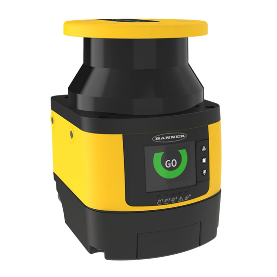
SX5 Safety Scanner Demo Kit Setup Instructions
Demo Kit DK-SX5-B Components List
•
Two-dimensional laser scanner effectively protects personnel and
stationary and mobile systems within a user-designated area
•
Individually define up to six Safety Zones and two Warning Zones
using a PC
•
Safety Zone range of 5.5 meters at 70 mm resolution or 3 meters
at 40 mm resolution
•
Highly flexible Safety and Warning Zones can be set to match the
shape of the work area
•
275° sensing angle
•
Suitable for horizontal, vertical, and AGV applications
First Steps
1. Download the SX5soft software from www.bannerengineering.com and install on a computer.
2. Launch the software.
3. Connect the power jack of the power supply into the mating connection located at the top of the I/O box.
4. Connect the 8-in Euro-style connector of the I/O Box to the matching connector on the SX5 scanner.
5. Plug the power supply into a wall outlet.
6. Open the rubber dust cover at the front of the SX5 scanner and connect the Ethernet cable's 4-pin Euro-style connector.
Connect the RJ45 end to your computer.
We recommend using the USB-to-Ethernet adapter (not included with the kit). This allows you to have an adapter configured for
Ethernet communication with the SX5 and keep the computer's built-in Ethernet adapter available for other uses.
Review of Display
Typical display icons seen during normal set up for static operation, assuming that a Warning Zone and manual reset is defined
All zones are clear
Display icons for diagnostic notes, warnings, and errors (19 icons possible)
Original Document
209666 Rev. A
Model
SX5-B
STP-M12D-406
Box with S22 Touch with In/Out Functions
Power Supply, 24 V, 1 A
within the configuration.
Warning zone interrupted
19 March 2019
Description
SX5 Safety Scanner
Cordset, M12 D-Code to RJ45
Safety Zone (SZ)
Warning Zone (WZ)
Safety zone interrupted
Waiting for a restart interlock
209666
Advertisement
Table of Contents

Related Manuals for Banner SX5 Series


Summary of Contents for Banner SX5 Series
- Page 1 SX5 Safety Scanner Demo Kit Setup Instructions Demo Kit DK-SX5-B Components List Model Description SX5-B SX5 Safety Scanner STP-M12D-406 Cordset, M12 D-Code to RJ45 Box with S22 Touch with In/Out Functions Power Supply, 24 V, 1 A • Two-dimensional laser scanner effectively protects personnel and stationary and mobile systems within a user-designated area •...
- Page 2 SX5 Safety Scanner Demo Kit Setup Instructions Downloading a new Override is active Clean the window Muting expired Check the input configuration sequence (zone switching) Selectable Menu Functions include: • Hardware information, such as name, part number, serial number, and firmware version •...
- Page 3 SX5 Safety Scanner Demo Kit Setup Instructions 3. Go to the Scanner menu and select Discovery. The software searches for any scanner connected to the network. The discovered demo kit SX5-B scanner is listed under the Discovery window with its assigned IP address. 4.
- Page 4 SX5 Safety Scanner Demo Kit Setup Instructions 11. Click on the right arrow to advance to the next screen. The Detection Configuration screen displays. This screen is for the Detection Configuration of the Safety Zone and, if included, the Warning Zone(s). Make no changes to the default settings on this screen for demo kit configuration 1. The Number of Scans can be set from 2 to as high as 16 if there are insects or other floating objects that could trip the scanner outputs.
- Page 5 The SX5-B safety scanner does not have available external device monitoring (EDM). The safety outputs (OSSD1 and OSSD2) will need to be connected to a safety-rated module or controller that has EDM monitoring (if necessary), such as Banner's UM-FA-FA module or the SC26/XS26 controllers.
- Page 6 SX5 Safety Scanner Demo Kit Setup Instructions 6. Select the rectangle pattern and enter the X, Y coordinates as shown (Start: -300, 0 and End: 300, 300). Click Draw. The red rectangle pattern for the safety zone is created. 7. Follow the same steps as for Demonstration Configuration #1 to upload the new configuration file to the scanner. 8.
- Page 7 4. While on the Monitoring Screen, click OK to the Warning box and OK to the Fault box. 5. Refresh the Monitoring screen by clicking on "Monitoring" at the tool bar. The screen status should be showing a green "GO". © Banner Engineering Corp. All rights reserved...
Need help?
Do you have a question about the SX5 Series and is the answer not in the manual?
Questions and answers