Table of Contents
Advertisement
Advertisement
Table of Contents

Subscribe to Our Youtube Channel
Related Manuals for Banner AG4 Series


Summary of Contents for Banner AG4 Series
- Page 1 Buy: www.ValinOnline.com | Phone 844-385-3099 | Email: CustomerService@valin.com...
-
Page 2: Safety Standards Applicable To Use Of This Product
Important . . . read this page before proceeding! In the United States, the functions that the Banner AG4 Series Safety Laser Scanner is intended to perform are regulated by the Occupational Safety and Health Administration (OSHA). Outside of the United States, these functions are regulated by other agencies, organizations, and governments. -
Page 3: About This Document
Banner AG4 Series Safety Laser Scanner About this Document The information for applying and configuring the Banner AG4 Safety Laser Scanner (the Scanner) is covered in several documents to simplify access to information. The documents and configuration program for the Scanner are on the CD that comes with the product. -
Page 4: Table Of Contents
Banner AG4 Series Safety Laser Scanner Table of Contents Safety Standards Applicable to Use of this Product ..........2 Certificate of Adequacy ....................2 About this Document ...................... 3 1. Overview ........................7 1.1 Status Display ......................7 1.2 Mounting System (Optional)..................8 1.3 Machine Interface X1 ConfigPlug ................ - Page 5 Banner AG4 Series Safety Laser Scanner 3. Installation ......................26 3.1 Basic Installation Procedure................... 27 3.2 Protective Field and Warning Field Considerations ..........28 3.3 Mechanical Installation Considerations ..............29 3.3.1 Unmonitored Areas ....................... 29 3.3.2 Needle- and Cone-Shaped Protective Field Contours ........... 31 3.3.3 Adjacent Scanners ......................
- Page 6 Banner AG4 Series Safety Laser Scanner 4.6.1 Resetting the System ....................69 4.7 Status Indicators ....................69 4.8 Normal Operation ....................69 4.8.1 System Power-Up ......................70 4.8.2 During Run Mode ......................70 4.9 Determining Response Time .................. 70 4.10 Periodic Checkout Requirements ................. 71 5.
-
Page 7: Overview
Banner AG4 Series Safety Laser Scanner 1. Overview The Banner AG4 Safety Laser Scanner (the Scanner) is an optical, two-dimensional measuring Safety Laser Scanner. The Scanner emits periodic light pulses via a rotating deflection mirror. The light pulses reflect back from objects in the sensing field and are then detected by the Scanner receiver. -
Page 8: Mounting System (Optional)
Banner AG4 Series Safety Laser Scanner LED Diagnostic Key Meaning Sensor function is active; the active Protective Field is clear. 1, green Flashes @ Fault on the Field Pair control 2 Hz inputs. Active Warning Field is interrupted. Flashes @ Front screen is dirty. -
Page 9: Product Labels
Carefully read, understand and follow the Instruction Manuals before using or installing this Scanner. The literature is contained within the software Help menu or can be downloaded at Banner website. The Scanner is intended for safeguarding machine hazards and collision avoidance on mobile vehicles. -
Page 10: Security Protocol And Checkout Procedures
If there is any doubt about whether or not your machinery is compatible with the Scanner, contact Banner's Application Engineers at the factory. Failure to follow all instructions and warnings could lead to serious bodily injury or death. -
Page 11: Passwords
Banner AG4 Series Safety Laser Scanner The safe design and construction of the machine. The safe implementation of the Scanner. Providing all relevant information to the user (e.g., all documentation provided with the AG4). Compliance with all regulations and directives that allow the user to safely put the machine into operation. -
Page 12: Handling The Scanner
Banner AG4 Series Safety Laser Scanner 1.10 Handling the Scanner Observe the permissible environmental conditions for storage and operation. Front Screen and Scatter Screens — The Scanner’s front screen and scatter screens must be clean, free of damage and properly installed. -
Page 13: Start/Restart (Reset) Interlock
Banner AG4 Series Safety Laser Scanner 1.12.1 Start/Restart (Reset) Interlock WARNING . . . MANUAL and AUTOMATIC START/RESTART (RESET) Application of power to the Scanner components, the clearing of the Protected Field (PF), or the reset of a start/restart interlock condition MUST NOT initiate dangerous machine motion. -
Page 14: Start Test
Banner AG4 Series Safety Laser Scanner Machine control circuitry is designed so that one or more initiation devices must be engaged (i.e., a conscious act is required) to start the machine – in addition to the Scanner turning ON its safety outputs (OSSD1 and OSSD2). - Page 15 Banner AG4 Series Safety Laser Scanner Note: Due to the timing requirements, it is recommended that the selection of Field Pairs 5, 6, 7, or 8 be made via PC, PES, or PLC logic. Additional switches or sensors can be used to enable (allow) Field Pair switchover.
- Page 16 Banner AG4 Series Safety Laser Scanner Table 1. Input Logic for Field Pair Control Control Input Wire Field Pair Description Field pair 1 is active Field pair 2 is active Field pair 3 is active Field pair 4 is active...
-
Page 17: Reference Contour (Surface) Monitoring
Banner AG4 Series Safety Laser Scanner 1.12.5 Reference Contour (Surface) Monitoring The reference contour (surface) monitoring function prevents unintentional misalignment and deliberate manipulation of the Scanner. If the Protective Field contains a reference contour (surface), the Scanner monitors both the Protective Field (for intrusions) and the reference surface (for field position). - Page 18 Banner AG4 Series Safety Laser Scanner be configured for a minimum of 80 ms to a maximum of 640 milliseconds (default = 160 ms). See Section 4 or the AG4Soft manual for more information. Alarm 1 (Auxiliary 1) output (X1 – 5) is configurable to provide status of the following; output turns OFF when: None (output is held OFF) ...
-
Page 19: Models And Specifications
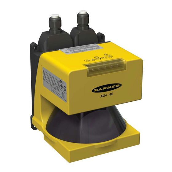
Banner AG4 Series Safety Laser Scanner 2. Models and Specifications 2.1 Models, Accessories and Replacement Parts Model Description AG4-4E 4 m max. range Laser Scanner; includes a 9-pin X2 plug, and a software CD that includes both hardware and software manuals; cordsets and bracket not included. Requires AG4-CPD15-.. machine interface cordset and AG4-PCD9-.. -
Page 20: Replacement Parts
Banner AG4 Series Safety Laser Scanner 2.1.3 Replacement Parts AG4-WIN1 Window with seal for AG4 Laser Scanner AG4- CPD15 Straight Config plug (connector), 15 pin, for AG4 auto-configuration AG4-PCD9 Straight plug (connector) and dust plug, 9 pin AG4 for X2 interface... - Page 21 Banner AG4 Series Safety Laser Scanner PNP open-collector transistor Alarm (Auxiliary) Outputs 1 & 2 Rated operating voltage: supply voltage (UB) -4 V Max. source current: 100 mA Residual voltage: 4 V or less Operation mode: Switching method of operation mode (set below)
-
Page 22: Dimensions
Banner AG4 Series Safety Laser Scanner 2.3 Dimensions R Cable bending radius (measurement is cable b Beam level All dimensions in mm. dependent); AG4-CPD15-.. minimum bend A Interface X1 for connection with control system radius 25 mm (1”) static, 89 mm (3.5”) flexible... - Page 23 Banner AG4 Series Safety Laser Scanner All dimensions in mm. Figure 2-2. AG4-MBK-1 Mounting system (optional accessory) dimensions Buy: www.ValinOnline.com | Phone 844-385-3099 | Email: CustomerService@valin.com...
-
Page 24: Connector Plug Assignments
Banner AG4 Series Safety Laser Scanner 2.4 Connector Plug Assignments X1 plug interface assignment Color code Signal Description blue 0V dc 24V dc common violet Reset Input, start/restart (reset) switch connection brown + 24V dc Supply voltage orange FP 1... - Page 25 Banner AG4 Series Safety Laser Scanner Interface assignment, plug X2 Plug X2 as RS 232 port Signal Description - - - Reserved Data communication, send Data communication, receive - - - Reserved GND/shield Ground/shield RS 232 Reserved – Not connected –...
-
Page 26: Installation
Banner AG4 Series Safety Laser Scanner 3. Installation Before installing the Scanner, read Sections 1 and 3 of this manual in their entirety. The System’s ability to perform its safety guarding function depends upon the appropriateness of the application and upon its proper mechanical and electrical installation and interfacing to the guarded machine. -
Page 27: Basic Installation Procedure
Banner AG4 Series Safety Laser Scanner 3.1 Basic Installation Procedure Note: A horizontal Protective Field is considered to be 30º or less from a level floor or walking surface. Identify the appropriate application from the choices in the Configuration Wizard (see table below). -
Page 28: Protective Field And Warning Field Considerations
Scanners), or prevent the Scanner from being used as a climbing aid. Ensure that these means do not impair the field of view. NOTE: See AG4 Series Safety Laser Scanner Application Guide (P/N 147900) for application check list items and application examples. -
Page 29: Mechanical Installation Considerations
Banner AG4 Series Safety Laser Scanner 3.3 Mechanical Installation Considerations Many factors influence the layout of the Scanner’s mechanical installation. For stationary applications, these include separation (safety) distance, supplemental safeguarding (hard guarding), unmonitored areas (shadows or areas behind the Scanner), adjacent Scanners, and the height of the Protective Field (in horizontal applications). In addition, mobile applications must take into account the stopping performance and distance of the mobile vehicle which the Scanner is controlling. - Page 30 Banner AG4 Series Safety Laser Scanner Recessing into the machine surface Physical cover Scanner Machine Figure 3-2. Recessing into the Machine Contour "Shadowing" Within the Protective Field WARNING . . . SHADOWING WITHIN THE PROTECTIVE FIELD Permanent and moveable objects in the Protective Field can create a shadow that results in an unprotected zone that may provide an access route to the hazard.
-
Page 31: Needle- And Cone-Shaped Protective Field Contours
Banner AG4 Series Safety Laser Scanner 3.3.2 Needle- and Cone-Shaped Protective Field Contours CAUTION . . . NEEDLE- AND CONE-SHAPED PROTECTIVE FIELD CONTOURS Any safety distance calculations must consider and resolve the effects of needle- or cone-shaped Protective Fields. Boundaries or contours that rely on too few measurement points (e.g., one or two) may not reliably turn OFF the OSSDs when an object is present. -
Page 32: Adjacent Scanners
Banner AG4 Series Safety Laser Scanner 3.3.3 Adjacent Scanners WARNING . . . ADJACENT SCANNERS Scanners that have a clear line of sight to another Scanner and that share the same detection plane with it, must be adjusted or shielded so that their light pulses are not detected by the adjacent Scanners, or 40 ms must be added to the response time of all adjacent Scanners. -
Page 33: Positioning Horizontal Protective Fields For Stationary Applications
Banner AG4 Series Safety Laser Scanner 3.3.3 Positioning Horizontal Protective Fields for Stationary Applications Height of the Protective Field Above the Floor or Walking Surface The Protective Field should not be located more than 1000 mm above the floor H. -
Page 34: Minimum Safety (Separation) Distance - Stationary Applications (Us Standards)
Banner AG4 Series Safety Laser Scanner WARNING . . . PROTECTIVE FIELD HEIGHT (STATIONARY HORIZONTAL FIELDS) Where the height of a horizontal Protective Field is H > 300 mm, there is a risk that a person can go undetected beneath the field. If it is possible for an individual to crawl undetected under the Protective Field and access the hazard, install supplemental guarding to prevent this access. - Page 35 Banner AG4 Series Safety Laser Scanner Dpf Considerations Vertical Protective Field Applications (Normal Approach) For Detection Capability (Resolution), where d ≤ 64 mm (2.5"), the formula for Dpf is: Dpf = 3.4 x (d – 7 mm) Dpf = 3.4 x (d - 0.275") where d = the Scanner’s Detection Capability (Resolution)
-
Page 36: Minimum Safety Distance - Stationary Applications (European Standards)
Banner AG4 Series Safety Laser Scanner is the additional distance needed to account for error due to reflections from retro reflective or shiny surfaces that refl are present in the scanning plane. No Retro-reflectors: Z refl Retro-reflectors located within the scanning plane of the Protective Field: Z = 100 mm (4") - Page 37 Banner AG4 Series Safety Laser Scanner Notes: The above formula is derived from ISO 13855 (2002). If S is greater than 500 mm, then K = 1600 mm/sec can be used instead of the 2000 mm/sec speed, however, if the 1600 mm/sec value is used, then S can never be less than 500 mm.
-
Page 38: Pass-Through Hazards
Banner AG4 Series Safety Laser Scanner Additional Scanner-Specific Distance Factors Two Scanner-specific factors must be considered when calculating the Minimum Safety distance: Z & Z refl Measurement Tolerance Factor is the additional distance needed to account for distance measurement error. The value for Z is a function of the distance from the Scanner (rotary mirror’s center point) to the furthest point of the Protective... -
Page 39: Reset (Start/Restart) Switch Location
Banner AG4 Series Safety Laser Scanner 3.3.7 Reset (Start/Restart) Switch Location The reset switch must be mounted at a location that complies with the warning below. If any hazardous areas are not in view from the switch location, additional means of safeguarding must be provided. The switch should be protected from accidental or unintended actuation (e.g., through the use of rings or guards). -
Page 40: Additional Installation Considerations For Mobile Applications
Banner AG4 Series Safety Laser Scanner Figure 3-11. An example of supplemental safeguarding Figure 3-11 shows an example of supplemental safeguarding inside a robotic work cell. The EZ-SCREEN LP safety light screen, in conjunction with the hard guarding, is the primary safeguard. Supplemental safeguarding (such as Scanners used as area guards) is required in areas that cannot be viewed from the reset switch (i.e., behind the robot and the... -
Page 41: Mounting
Banner AG4 Series Safety Laser Scanner The user must instruct all individuals that may interact with the mobile vehicle (at a minimum): not to approach the vehicle directly or from the sides while moving familiarize with warning signals or lights/beacon ... -
Page 42: Protective Field Area - Length And Width
Banner AG4 Series Safety Laser Scanner Maximum Protective Field range: AG4-4E = 4 m (13.2'); AG4-6E = 6.25 m (20.6') Start/Restart Interlock selectable (Manual or Auto reset) Default = Automatic Start and Restart enabled (Auto) Start/Restart (Reset) Interlock The default configuration is automatic start and restart (automatic reset) with a 2 second delay after the Protective Field becomes clear. - Page 43 Banner AG4 Series Safety Laser Scanner WARNING . . . DETERMINE CORRECT STOP TIME Stop time (T ) must include the response time of all relevant devices or controls that react to stop the mobile vehicle. If all devices are not included, the calculated Minimum Distance (D) will be too short.
- Page 44 Banner AG4 Series Safety Laser Scanner = [V x (T )] + D where: = Stopping distance in mm = the maximum velocity as stated by the manufacturer of the mobile vehicle = maximum stop time (in seconds) of the mobile vehicle (see note 1 below)
- Page 45 Banner AG4 Series Safety Laser Scanner Figure 3-14. Diagram to determine the additional distance Z with lack of floor clearance H Application-Specific Additions is the additional distance needed to account for factors that can otherwise affect the safe application of the Scanner.
-
Page 46: Mobile Side Guarding On Agvs (Vertical Protective Fields)
Banner AG4 Series Safety Laser Scanner 3.4.4 Mobile Side Guarding on AGVs (Vertical Protective Fields) If the Additional Side Distance Z cannot be complied with or if additional safeguarding is otherwise required, additional AG4 vertical Protective Fields can be used (see Application Guide p/n 147900). -
Page 47: Electrical Connections
This must be done per local wiring code for low-voltage dc control cables and may require installation of electrical conduit. See Sections 2.1.1 and 2.4 for information about Banner-supplied cables. Do the same with the PC interface cable if it is to be permanently installed; if this connection is only to be used during configuration (or troubleshooting), route the cable to the PC such that it does not interrupt the scanning field. -
Page 48: Initial Electrical Connections
Banner AG4 Series Safety Laser Scanner 1 X1 Machine Interface (15-pin sub-D) 2 X2 PC Interface (9-pin sub-D) 3 X2 PC Interface cable 4 X2 Dust/protective cap Figure 3-16. Scanner Interconnections 3.5.2 Initial Electrical Connections Ensure that electrical power is not applied to the Scanner until told to do so. Do not connect any wires to the machine control circuits (i.e., OSSD outputs) at this time. -
Page 49: Initial Power-Up And Configuration Of The Scanner
Banner AG4 Series Safety Laser Scanner 3.6.1 Initial Power-Up and Configuration of the Scanner Verify that: Power has been removed from (or is not available to) the guarded machine, its controls or actuators; The machine control circuit or the safety module is not connected to the OSSD outputs at this time (permanent ... -
Page 50: Trip Test (Protective And Warning Field Verification)
Banner AG4 Series Safety Laser Scanner In RUN mode, observe the Scanner's status indicators to determine status, see Table 8 and Section 5. If a status indicator begins to flash at any time, the Scanner has entered an error or lockout condition. See Section 5.1 for further information. -
Page 51: Electrical Interface To The Guarded Machine
Banner AG4 Series Safety Laser Scanner Figure 3-17. Scanner trip tests – horizontal (field perimeter) and vertical (off the floor) Repeat steps 1 through 4 for each of the Field Pairs that have been configured if Field Pair Switchover is used. -
Page 52: Fsd Interfacing Connections
Banner AG4 Series Safety Laser Scanner Final switching devices (FSDs) typically accomplish this when the OSSDs go to an OFF state. See Figure 3-19. Refer to the output specifications in Section 2.2 and the warnings below before making OSSD output connections and interfacing the Scanner to the machine. -
Page 53: Machine Primary Control Elements And External Device Monitoring
Banner AG4 Series Safety Laser Scanner and the MPCEs are located in different enclosures. For this reason, dual-channel control with EDM monitoring should be used in any installation where the FSDs are located remotely from the MPCEs. Single-Channel Control Single-channel control uses a series connection of FSD contacts to form a safe switching point. After this point in the machine’s safety-related control system, failures can occur that would result in the loss of the safety function (such as a... -
Page 54: Notice Regarding Mpces
Banner AG4 Series Safety Laser Scanner The principle of fault exclusion allows the designer to design out the possibility of various failures and justify it through the risk assessment process to meet the required level of safety performance, such as the requirements of Category 2, 3 or 4. - Page 55 Banner AG4 Series Safety Laser Scanner Figure 3-18. Hookup with FSD inputs Buy: www.ValinOnline.com | Phone 844-385-3099 | Email: CustomerService@valin.com...
- Page 56 Banner AG4 Series Safety Laser Scanner Figure 3-19. Hookup using UM module Buy: www.ValinOnline.com | Phone 844-385-3099 | Email: CustomerService@valin.com...
- Page 57 Banner AG4 Series Safety Laser Scanner Figure 3-20. Hookup to the SC22-3 Safety Controller Buy: www.ValinOnline.com | Phone 844-385-3099 | Email: CustomerService@valin.com...
-
Page 58: System Operation And Configuration
Banner AG4 Series Safety Laser Scanner 4. System Operation and Configuration 4.1 Security Protocol Certain procedures for installing, maintaining and operating the Scanner must be performed by either Designated Persons or Qualified Persons. A Designated Person is identified and designated in writing, by the employer, as being appropriately trained to perform the specified checkout procedures on the Scanner. - Page 59 Banner AG4 Series Safety Laser Scanner NOTE: A dialog box may appear that says that there is a problem in identifying a serial port. If so, see Section 4.3.1 Establishing Communications Between the PC and the Scanner. A dialog box should appear and ask if you would like to edit the configuration with the wizard; if so, click OK. If not prompted, the wizard can also be accessed by clicking on the ―...
- Page 60 Banner AG4 Series Safety Laser Scanner Select ― Freely Selectable Presettings‖ (for the purposes of this walk-through). While the resolution is fixed at 70 mm, this option allows the most flexibility in learning the wizard. The restart behavior default option is ― Restart Interlock‖ (Manual Reset). If Automatic restart (auto reset) is chosen, the ―...
- Page 61 Banner AG4 Series Safety Laser Scanner The final dialog boxes in the wizard are considered ― Administrative Parameters‖ and allow configuration of the functionality of Alarm Output 1 (see Section 1.12.6), the amount of measurement data that is communicated (see Section 1.12.5), and the baud rate of the X2 PC serial interface.
- Page 62 Banner AG4 Series Safety Laser Scanner After these parameters have been configured (use defaults for the walk-through), click OK to return to the main Configuration screen, which is indicated by the yellow highlighted tab on the top toolbar (i.e., Operating Mode Tabs).
- Page 63 Banner AG4 Series Safety Laser Scanner It should be noted that the proper ―Ope rating Mode‖ tab must be highlighted (yellow) for the appropriate options within the Menu Bar to be active. These options are generally duplicated via the Operating Mode Icons (some listed below).
-
Page 64: Configuration Wizard: Changing Protective And Warning Fields
Banner AG4 Series Safety Laser Scanner 4.2.2 Configuration Wizard: Changing Protective and Warning Fields To modify or create the shape of the Protective and Warning Fields, click on ―Pro tective/Warning Fields definition‖ tab on the Operating Mode Tabs. Notice that the selection of the Operating Mode icons has changed. (See AG4Soft Software Manual for complete descriptions.) - Page 65 Banner AG4 Series Safety Laser Scanner Field definition icons 20 through 23 are typically used to create general field shapes. ― Enter Protective/Warning Field numerically‖ (20) creates a rectangular field by entering a distance in millimeters to the front edge and to both sides.
-
Page 66: Configuration Wizard: Saving The Configuration
Banner AG4 Series Safety Laser Scanner The cursor can also be used to click and drag to create a zoom box, in which the values of opposite corners are displayed as the ―Po sition‖ and ―En d position‖. Left-click to ― set‖ a point (Position). Right-click to ―f inish‖ (End position). -
Page 67: Establishing Communications Between The Pc And The Scanner
Banner AG4 Series Safety Laser Scanner Manipulating the Uploaded Configuration The configuration can be changed via the wizard (Configuration Operating Mode tab highlighted: Configuration > Wizard), or by manually changing settings and fields via the ―Co nfiguration‖ and the ―Pr otective/Warning Fields definition‖... -
Page 68: Opening A Configuration File (".Rs" Files)
Banner AG4 Series Safety Laser Scanner Open AG4Soft program Connect the AG4-PCD9-xx serial cordset to the AG4-PC9USB-1 (or at the X2 connector on the AG4) Note: If repeated communication loss occurs, check for secure connections, ensure AG4-PCD9-xx cordset (with RS232 communication) are used, and/or shorten the overall cable length. -
Page 69: Downloading A Configuration To The Scanner
Banner AG4 Series Safety Laser Scanner Configuration ―. rs‖ files are accessible from the top Menu Bar: click on File > Load configuration data from file and select an ―.r s‖ file to open, then click on Protective/Warning Fields > Transfer changed Protective/Warning Fields from PC to Scanner. -
Page 70: System Power-Up
Banner AG4 Series Safety Laser Scanner Restart Interlock with Start Interlock (Manual Reset) Automatic Restart Interlock with Start Interlock (Automatic Reset with manual power-up) Automatic Restart Interlock with Automatic Start (Automatic Reset) Automatic Restart Interlock with Start Test (Automatic Reset with test at power-up) In any case, the clearing of the Protected Field (PF), or the reset of a start/restart interlock condition MUST NOT initiate dangerous machine motion. -
Page 71: Periodic Checkout Requirements
Banner AG4 Series Safety Laser Scanner Protective Field (PF) response time: Time until the Scanner switches off the OSSD 1 and OSSD 2 safety outputs or switching function (Default = 80 ms). Warning Field (WF) response time: Time until the Scanner switches off the Alarm output (Default = 80 ms). -
Page 72: Troubleshooting And Maintenance
Create a service file with the configuration and diagnostics software and send this service file for remote diagnostics to Banner (see AG4soft Software Instruction Manual for more information). Refer to Figure 5-1 for LED names and locations. - Page 73 Banner AG4 Series Safety Laser Scanner Five LEDs on the housing front show the Scanner's operating status. LED Diagnostic Key Meaning Sensor function is active; the active Protective Field is clear. 1, green Flashes @ Fault on the Field Pair control 2 Hz inputs.
-
Page 74: Led Status Displays
Banner AG4 Series Safety Laser Scanner 5.1.2 LED Status Displays Table 9. LED status displays LEDs Status Activity Gree Yellow Gree Yellow • Boot process, configuration process • Safety outputs or switching function are switched off. 2 x (1) 2 x (1) • Boot process, configuration process •... -
Page 75: Led Warning And Error Displays
Banner AG4 Series Safety Laser Scanner 5.1.3 LED Warning and Error Displays Table 10. LED diagnostic codes (see signal key at bottom) LED signals Status Activity Gree Yell Gree Yell • The sensor function is active; the active Protective Field is free. -
Page 76: Scanner Error Codes
Banner AG4 Series Safety Laser Scanner 5.1.2 Scanner Error Codes A diagnostics list can be created with the AG4Soft software. The incidents that occurred during the Scanner operation are listed in this diagnostics list. Each incident is given with place and number. The meaning of the incidents is shown in the following table. - Page 77 Banner AG4 Series Safety Laser Scanner Place Number Meaning Activity Safety outputs or switching function (OSSDs) cannot 1110 Check the connection/wiring of the OSSDs. be switched, short-circuit with 0 V DC or +24 V DC. Safety outputs or switching function (OSSDs) cannot...
- Page 78 Banner AG4 Series Safety Laser Scanner Place Number Meaning Activity Safety outputs or switching function (OSSDs) cannot Check the connection/wiring of the OSSDs. If reset is not successful, 1906 be switched, internal or external short-circuit. contact customer service Read back error on the safety outputs or switching Check the connection/wiring of the OSSDs.
- Page 79 Banner AG4 Series Safety Laser Scanner Place Number Meaning Activity Motion Monitoring, a Protective Field length does not Check all parameters in the wizard, calculate the Protective Fields again 2018 match the predefined braking distance of the vehicle. and start the transfer again.
- Page 80 Banner AG4 Series Safety Laser Scanner Place Number Meaning Activity The Protective Field switchover performed does not comply with the specifications programmed in the 2800 Check the activation of the Protective Fields in the program wizard. Scanner. More than 2 Protective Fields are activated during 2800 Check the activation of the control inputs FP1 - FP4.
- Page 81 Banner AG4 Series Safety Laser Scanner Place Number Meaning Activity Scanner 3203 has optical glare caused by another device. Switch off the supply voltage and start the Scanner again. Motion Monitor, Field Pair activated wrong several Check the activation of the Protective Fields in the speed matrix and the 3402 times.
-
Page 82: Communication Errors And Loss Of Communication
Banner AG4 Series Safety Laser Scanner 5.2 Communication Errors and Loss of Communication See Section 4.3 ―Con necting to the Scanner‖ and Section 4.3.1 ― Establishing Communications Between the PC and the Scanner‖ for general information concern such items as ―Co nfiguring the PC Serial Port‖, ― Loss of Communications‖, and USB-to-serial adaptors, including the AG4-PCD9USB-1. -
Page 83: Electrical And Optical Noise
Checking for sources of optical noise: Turn off the Scanner. Then use a Banner BT-1 Beam Tracker to check for light at the AG4 front screen (window) by press the ―RC V ‖ button on the BT-1 and moving across the full length of the window with the BT-1 lenses facing away from the AG4. -
Page 84: Cleaning The Scatter Screens
Banner AG4 Series Safety Laser Scanner Wet with cloth soaked in AG4 cleanser Particles/drops, smearing Wipe free in one swipe with cleaning cloth Water drops Wipe free in one swipe with cleaning cloth Wet with cloth soaked in AG4 cleanser... -
Page 85: Changing The Front Screen (Window)
Banner AG4 Series Safety Laser Scanner 5.4.4 Changing the Front Screen (Window) If the front screen is scratched, replace it. Only a Qualified Person may change the front screen. It is changed in two steps: Change the front screen Calibrate the front screen When replacing the Scanner front screen due to contamination or similar: Perform all work in a dust-free environment if possible. -
Page 86: Calibrating The Front Screen (Window)
Banner AG4 Series Safety Laser Scanner Check that there is no gap of light between the front screen and the housing. Fix the front screen with the fixing plates. 10. Support while screwing the fixing plates with a little pressure on the furthest outside edge of the front screen. -
Page 87: Scanner Replacement Procedure
(window) as described in Section 5.4.2. The Scanner contains no other field-replaceable components. If repair is necessary, do not attempt to repair yourself; return the unit to the factory, as follows. Contact a Banner Factory Application Engineer at the address or numbers listed on the back cover of this document, or below: Banner Engineering Corp.,... -
Page 88: Safety System Testing
Study each procedure in its entirety, to understand each step thoroughly before beginning. Refer all questions to a Banner applications engineer, at the address or numbers listed on the back cover of this manual. Checkouts must be performed as detailed in Section 6.1 below and results must be recorded and kept in the appropriate place (e.g., near the machine, and/or in a technical file). -
Page 89: Commissioning Checkout
Banner AG4 Series Safety Laser Scanner 6.2 Commissioning Checkout Perform this checkout procedure as part of the Scanner installation (after it has been interfaced to the guarded machine as described in Sections 3.5 and 3.7), or whenever changes are made to the system (either a new configuration of the Scanner or changes to the machine). - Page 90 14. Test the machine stopping response time, using an instrument designed for that purpose, to verify that it is the same or less than the overall system response time specified by the machine manufacturer. (A Banner Applications Engineer can recommend a suitable instrument.)
-
Page 91: Shift/Daily Checkout
Tester: Designated Person or Qualified Person (as described in Section 4.1). Refer to the procedure contained on the Daily Checkout card (Banner p/n 147899) contained on the software disc included with the Scanner. If the checkout card is missing, contact Banner Engineering or download at Banner website. -
Page 92: Glossary
Banner AG4 Series Safety Laser Scanner 7. Glossary 7.1 List of Abbreviations European Conformity mark Danger Zone External Device Monitoring Final Switching Device International Electrotechnical Commission IP... Ingress Protection International Organization for Standardization Light Emitting Diode OSSD Output Signal Switching Device... - Page 93 Banner AG4 Series Safety Laser Scanner Protective Field – The Scanner effective Separation (safety) distance/Safety distance that is required to stop the machine before a person who enters the Protective Field reaches the machine and is specified in ISO 13855 and associated standards.
-
Page 94: Ec Declaration Of Conformity
Minneapolis, MN 55441-5019 USA We herewith declare that the Banner AG4 Series Safety Laser Scanner for industrial control is in conformity with the provisions of the Machinery Directive (Directive 98/37/EC Machinery Directive [valid until 29 December 2009] and 2006/42/EC Machinery Directive), and all essential Health and Safety Requirements have been met.
Need help?
Do you have a question about the AG4 Series and is the answer not in the manual?
Questions and answers