
Subscribe to Our Youtube Channel
Related Manuals for ATV 22X MINITRAX III


Summary of Contents for ATV 22X MINITRAX III
- Page 1 INSTRUCTION MANUAL 22X MINITRAX III DOME CAMERA Please read this manual thoroughly before use and keep it handy for future reference.
-
Page 2: Explanation Of Graphical Symbols
CAUTION EXPLANATION OF GRAPHICAL SYMBOLS The lightning flash with arrowhead symbol, within an equilateral triangle, is intended to alert the user to the presence of uninsulated “dangerous voltage” within the product’s enclosure that may be of sufficient magnitude to constitute a risk of electric shock to persons. -
Page 3: Fcc Compliance Statement
FCC COMPLIANCE STATEMENT FCC INFORMATION: This equipment has been tested and found to comply with the limits for a Class A digital device, pursuant to Part 15 of the FCC Rules. These limits are designed to provide reasonable protection against harmful interference when the equipment is operated in a commercial environment. -
Page 4: Important Safety Instructions
IMPORTANT SAFETY INSTRUCTIONS 1. Read these instructions. 2. Keep these instructions. 3. Heed all warnings. 4. Follow all instructions. 5. Clean only with dry cloth. 6. Do not block any ventilation openings. Install in accordance with the manufacturer’s instructions. 7. Do not install near any heat sources such as radiators, heat registers, stoves, or other apparatus (including amplifiers) that produce heat. -
Page 5: Table Of Contents
Table of Contents Chapter 1 — Introduction......................1 1.1 Features ............................. 1 Chapter 2 — Installation and Configuration ................. 2 2.1 Package Contents..........................2 2.2 Installation ............................3 2.3 Basic Configuration of Dome Camera System ................ 4 2.4 Setting Dome Camera Termination ..................... 5 2.5 Setting Dome Camera Address (ID) .................... -
Page 6: Chapter 1 - Introduction
Chapter 1 — Introduction 1.1 Features The dome camera and the keyboard controller make up the building blocks for any surveillance/security system. Using multiple keyboard controllers and multiple dome cameras, no place is too large for monitoring. Extensible and flexible architecture facilitates remote control functions for a variety of external switching devices such as multiplexers and DVRs. -
Page 7: Chapter 2 - Installation And Configuration
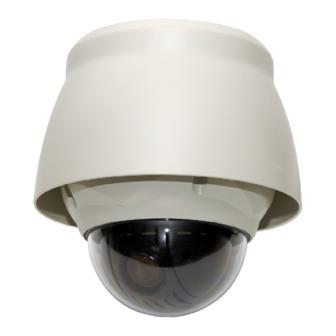
Chapter 2 — Installation and Configuration 2.1 Package Contents The dome camera is designed with a compact, small size, hard dome camera housing. The housing is constructed of aluminum, steel and plastic. The housing is designed to be mounted on a wall or a ceiling. The housing meets the Protection Classification IP66 standards for dust and moisture resistance. -
Page 8: Installation
2.2 Installation You need one optional mount kit of the wall mount and the ceiling mount to install. The wall or ceiling mount must be attached to a structural object such as hard wood, concrete that will support the weight of the mount and dome camera. The use of a solid backboard is recommended when attaching to gypsum walls. -
Page 9: Basic Configuration Of Dome Camera System
2.3 Basic Configuration of Dome Camera System Figure 1 – Basic Installation Diagram The dome camera must be installed by qualified service personnel in accordance with all local and federal electrical and building codes. -
Page 10: Setting Dome Camera Termination
Figure 2 – Layout of DIP Switches NOTE: Open the switch cover (position “a”) and change the setting of DIP switches. The cover should be closed after setting DIP switches. 2.4 Setting Dome Camera Termination The device which is connected at end of line, whether it is a dome camera or keyboard controller, must have the cable for communication terminated by setting the appropriate DIP switch. - Page 11 Example: Port 1 = Dome 1, Port 2 = Dome 2 … Port 16 = Dome 16. If more than 16 dome cameras are installed using two or more multiplexers, ID of the dome camera should be ID of MUX x No. of camera IN. (e.g. multiplexer ID= n, Camera IN= m then ID of Dome =16x(n-1)+m ) DOME ID (16) (32)
- Page 12 DOME ID (16) (32) (64) (128) Figure 4.2 – Setting Dome Camera Address (ID)
- Page 13 DOME ID (16) (32) (64) (128) Figure 4.3 – Setting Dome Camera Address (ID)
- Page 14 DOME ID (16) (32) (64) (128) Figure 4.4 – Setting Dome Camera Address (ID)
- Page 15 DOME ID (16) (32) (64) (128) Figure 4.5 – Setting Dome Camera Address (ID)
- Page 16 DOME ID (16) (32) (64) (128) Figure 4.6 – Setting Dome Camera Address (ID)
-
Page 17: Setting Dome Camera Protocol And Video
2.6 Setting Dome Camera Protocol and Video If a dome camera is to be installed with the keyboard controller, select the default protocol. Consult service personnel if a dome camera is installed with device other than a keyboard controller. S2-D1 You can set video type with DIP switch. -
Page 18: Getting Started
• Connecting Alarms A1,A2,A3,A4 (Alarm Input 1,2,3,4) You can use external devices to signal the dome camera to react on events. Mechanical or electrical switches can be wired to the A1,A2,A3,A4 (Alarm Input 1,2,3,4) and G (Ground) connectors. See Chapter 3 — Program and Operation for configuring alarm input. G (Ground) NOTE: All the connectors marked G or GND are common. -
Page 19: Chapter 3 - Program And Operation
The dome can move the OSD position in the OSD position setup. (AREA TITLE) (AF AE) (FUNC TITLE (CTRL KEY TO MOVE) SAVE AND EXIT(ESC TO CANCEL) (ALARM MESSAGE) (DOME ID…) (ANGLE…) OSD Position Setup Chapter 3 — Program and Operation 3.1 Dome Camera Selection Before you program or operate a dome camera, you must select the dome camera by pressing No. -
Page 20: How To Control The On-Screen Menu Utility
3.3 How to control the On-Screen Menu Utility Function Button Call the On-screen menu utility. MENU Navigate through the menu items. Joystick up or down Go into the sub-menu items. Joystick left or right or IRIS Open Joystick left or right or Change value. - Page 21 4. Twist the Joystick to change the alphanumeric characters and move the next position by pushing the Joystick to the left or right. Or move down to the character table and press the CTRL or IRIS Open key at the desired character then the cursor position moves to the next position automatically.
-
Page 22: Preset (Shortcut: Prst)
Press the SCAN key on the angle field to display with the small OSD. Then the screen will show as below. AUTO SCAN AREA SETUP (CTRL KEY) NUMBER01 START : ----- ----- : ----- ----- EXIT(ESC TO EXIT) The setting procedure is the same as above. NOTE: 09: AUTO-PAN mode (endless panning) 3.5 Preset (Shortcut: PRST) - Page 23 4. After aiming the camera (view direction and lens control), release the CTRL key. The cursor will be on the “TITLE” after saving data then twist the Joystick or press the Tele or Wide key to edit the Preset title. Follow the procedure of the Auto Scan above to edit titles. 5.
-
Page 24: Shortcut Of Preset Program
The position, which is marked with the *, already has the Preset view assigned. Press the PRST key on the * to review the stored Preset. The camera will show the stored Preset scene. PRESET AREA SETUP (CTRL KEY) NUMBER 001 TILT 000.0 000.0 EXIT(ESC TO EXIT) - Page 25 : Auto Scan (1 ~ 8, 10 ~ 17) : Pattern (1 ~ 8) : Tour (1 ~ 8) Follow the steps below to program the Tours: 1. Press the MENU key to display the main menu on the monitor. Scroll to Tour and push the Joystick to the right to enter the Tour menu.
-
Page 26: Pattern (Shortcut: Ptrn)
3.8 Pattern (Shortcut: PTRN) The Pattern feature records user control of the selected dome camera. Up to 8 Patterns can be stored and played back by pressing No. + PTRN keys subsequently. PATTERN SETUP (CTRL KEY) TITLE PERCENT 01 : P01 00.0% 02 : P02 00.0%... -
Page 27: Alarm
3.9 Alarm ALARM SETUP PRI FUN IN HLD LATCH 001 NO --- OFF OFF --- OFF OFF --- OFF OFF DWELL ALARM OUT SETUP SAVE AND EXIT(ESC TO CANCEL) : alarm input number PRI(Priority) : The lower number has higher priority. (0 ~ 4) FUN(Function) : Stored function number to be called by alarm. -
Page 28: Privacy Zone
TITLE : up to 12 characters. SWAP : Swap the start point for the end point. 1. Select “NUMBER” and set the desired number by pushing the Joystick to the left or right. 2. To edit the “TITLE”, follow the procedure of the Auto Scan above to edit titles. 3. -
Page 29: Camera Menu
3. Place the cursor at the “TITLE” field. Twist the Joystick to enter the title edit mode. Follow the procedure of the Auto Scan above to edit titles. 4. To turn the stored zone On or Off, twist the Joystick or press the Tele or Wide key. 5. - Page 30 FOCUS LIMIT This distance is approximate value and the focus operate from the setting value. CAUTION: Avoid continuous, 24-hour use of the auto focus. This will shorten the lifespan of the lens. • WB (White Balance) CONTROL WB SETUP MODE : AWB R GAIN : ---...
- Page 31 OFF / ON (NOTE: When ON, BACKLIGHT will be disabled.) WDR LEVEL LOW / MIDLOW / MID / MIDHIGH / HIGH NIGHT SHOT AUTO / ON / OFF / GLOBAL NOTE: Values in ( ) are for PAL Camera. The WDR operates in AE1 mode only. NOTE: When BACKLIGHT set BLC or HLC, focus issues may occur in certain lighting conditions.
-
Page 32: Dome Setup
3.13 Dome Setup CONFIGURATION MENU LANGUAGE : ENGLISH HOME FUNCTION SETUP OSD DISPLAY VIEW ANGLE SETUP INITIALIZE DATA ORIGIN OFFSET DOME RESET SYSTEM MENU SYSTEM INFORMATION SAVE AND EXIT(ESC TO CANCEL) • LANGUAGE SETUP LANGUAGE : Select the desired language. •... - Page 33 • OSD DISPLAY OSD DISPLAY SETUP CAMERA TITLE : DOMEID VIEW DIRECTION : OFF DOME OSD : ON AREA TITLE : OFF PRESET TITLE : CONSTANT FOCUS EXPOSURE : ON OSD POSITION SETUP SAVE AND EXIT(ESC TO CANCEL) CAMERA TITLE : up to 6 characters VIEW DIRECTION : ON / OFF...
- Page 34 • VIEW ANGLE SETUP VIEW ANGLE SETUP PANNING RANGE FLIP : 90° TILT LIMIT : OFF SAVE AND EXIT(ESC TO CANCEL) FLIP: OFF, AUTO, 90°, 100°, 110°, 120°, OFF: The dome camera moves until 90° vertically. AUTO: When the camera reaches the floor directly above the moving object, it will stop. At that time, release the Joystick instantly and pull it down again to run the auto-flip function.
- Page 35 • INITIALIZE DATA INITIALIZE DATA FACTORY DEFAULT ERASE PROGRAMMED DATA PRESET FOCUS DEFAULT EXIT(ESC TO EXIT) FACTORY DEFAULT Select “FACTORY DEFAULT” to initialize the data. FACTORY DEFAULT ARE YOU SURE ? CANCEL ERASE PROGRAMMED DATA Erase all stored data from the Flash-ROM of the selected dome camera. You will be asked to enter ON or OFF.
- Page 36 • ORIGIN OFFSET OFFSET SETUP (CTRL KEY) PAN OFFSET : 000.0 TILT OFFSET : 000.0 ENABLE : OFF SAVE AND EXIT(ESC TO CANCEL) This feature is useful to align a new dome camera exactly the same as the previously installed dome camera.
- Page 37 MOTOR SETUP Motor Setup menu provides the pan and tilt speed of a camera. User can set the desired speed with pushing the Joystick to the left or right. During operation, pressing 153 + ON keys will change the speed to the SLOW mode and pressing 153 + OFF keys will change the speed to the Normal mode.
-
Page 38: Function Run
WHITE DEFECT COMPENSATION White defect of CCD sensor will be compensated. WHITE DEFECT COMPENSATION ARE YOU SURE ? CANCEL • SYSTEM INFORMATION SYSTEM INFORMATION CAMERA TYPE : xxxxx-Vx.xxxx H/W VERSION : Vx.xx-xxxx ROM VERSION : Vx.xxxxx PROTOCOL : xxxx BAUDRATE : 9600 EXIT(ESC TO EXIT) The system information provides essential information about the dome camera if service is... -
Page 39: Factory Setup
- HOME Select “HOME” and press the CTRL key. The dome camera goes to the default position that it returns to after an assigned period of inactivity passes. The default position may be a Preset, Tour, Pattern or no action. - AUTO PAN You can execute the endless auto pan to turn in one direction continuously by selecting Auto Pan. -
Page 40: Appendix A - Specifications
Appendix A — Specifications 22X MINITRAX III DOME CAMERA MODEL MODULE CCD Type 1/4" Type Super HAD CCD II Optical / Digital Zoom 22X / 16X Max Resolution 700 TVL Focal Length f = 3.9mm ~ 85.8mm 3.9mm – 49.5° (H) Angle of View 85.8mm –... - Page 41 Figure 6 – Dimension...
-
Page 42: Appendix B - Troubleshooting
Appendix B — Troubleshooting If problems occur, verify the installation of the camera with the instructions in this manual and with other operating equipment. Isolate the problem to the specific piece of equipment in the system and refer to the equipment manual for further information. Problem Possible Solution Verify that power is connected to all pieces of... -
Page 43: Home Position
On-screen Menu The text overlay menu system used for setting dome features. The utility is accessed using a keystroke combination. The utility provides settings for camera functions, zoom, alarm, text display, and password protection. Flip Allows the dome to automatically turn 180 degrees when the camera tilts to its lower limit and stays in that position for a brief delay. -
Page 44: Slow Shutter
Slow Shutter Setting used to improve the quality of video obtained in extreme low-light situations. When the Slow Shutter setting is enabled, low-light information is collected over multiple fields based on the Shutter Limit setting. As a result, video may appear blurred or choppy in extreme low-light situations. -
Page 45: Appendix D - Short Cut Key
Appendix D — Short Cut Key Short Cut Key Function PRST Pop up Preset setup menu TOUR Pop up Tour setup menu PTRN Pop up Pattern setup menu SCAN Pop up Auto Scan setup menu No.+ CTRL+ PRST Store the current view at the selected number Short Cut Key Function Short Cut Key... -
Page 46: Appendix E - Wall Mount
Appendix E — Wall Mount The wall mounting plate must be attached to a structural object such as concrete that will support the weight of the mount and Dome Camera. 1. Select a suitable mounting location and verify there is sufficient cable to reach the middle of the Wall Mount. -
Page 47: Appendix F - Ceiling Mount
Appendix F — Ceiling Mount The ceiling mounting plate must be attached to a structural object such as concrete that will support the weight of the mount and Dome Camera. 1. Select a suitable mounting location and verify there is sufficient cable to connect with cables from the housing. - Page 48 22X MINITRAX III DOME CAMERA Printed in Korea 50303340A...
Need help?
Do you have a question about the 22X MINITRAX III and is the answer not in the manual?
Questions and answers