Table of Contents
Advertisement
Quick Links
Advertisement
Chapters
Table of Contents
Troubleshooting

Related Manuals for Compal JHL90


Summary of Contents for Compal JHL90
- Page 1 Service Manual JHL90...
-
Page 3: Chapter 1 System Description Specification
Chapter 1 System Description Specification... -
Page 5: Table Of Contents
Contents Chapter 1 System Description Specification 1. SCOPE ....................1-2 One 2.5” W, 9.5mm H Hard Disk, Up to 250GB......1-2 Optical Disc Drive ................1-2 Touch Pad:..................1-2 Keyboard ..................1-2 Display Device ................1-2 Camera..................1-3 Keyboard ..................1-3 2. Communications ..................1-4 Wireless LAN .................1-4 Modem...................1-4 Bluetooth ..................1-4 3. - Page 7 JHL90 Service Manual IMPORTANT SAFETY INSTRUCTIONS When using your telephone equipment, basic safety precautions should always be followed to reduce the risk of fire, electric shock and injury to persons, including the following: ★ Do not use this product near water, for example, near a bathtub, washbowl, and kitchen sink or laundry tub, in a wet basement or near a swimming pool.
-
Page 8: Scope
JHL90 Service Manual SCOPE This document describes the functional specifications for the Compal Notebook personal computer JHL90 series. The system is hardware and software compatible with the IBM PC/ATX personal computer. One 2.5” W, 9.5mm H Hard Disk, Up to 250GB •... -
Page 9: Camera
JHL90 Service Manual 1440 x 900 WXGA+Resolution Brightness: 185 Nit (Type) • COLOR TFT/WXGA LCD (CMO N154Z1-L02 Glare) Dimensions: 344.5 (W) x 222.5 (H) x 6.5 (D) mm (max) 1680 x 1050 WSXGA+ Resolution Brightness: 200 Nit (Type) • COLOR TFT/WXGA LCD (LPL LP154WE2-TLA7) Dimensions: 344.0 (W) x 222.0 (H) x 6.5 (D) mm (max) -
Page 10: Communications
JHL90 Service Manual Communications Wireless LAN • Wireless LAN & WiMAX mini card: module maker: Intel PCI Express base specification compliant Wireless LAN mini card: 802.11 abgn,marker: shirley peak Modem • Internal Modem with MDC solution (MDC 3.3/1.5): module maker: Askey Bluetooth •... -
Page 11: Mechanical Specification
JHL90 Service Manual Mechanical Specification • FOR15.4” JHL90 14.11” (W) x 10.19” (D) x 1.54” (H) [358.5mm (W) x 259mm (D) x 39.2mm (H)] 5.8 lb~5.3 lb (including: HDD, CD-ROM, and BATT module) Option Pack: • AC adapter: 444g • HDD Pack: 160g (9.5mm) •... - Page 13 Chapter 2 Software Specification...
- Page 15 Contents Chapter 2 Software Specification 1. System Components Summary .............. 2-1 2. System Controls ..................2-5 Buttons ..................2-5 System status indicators..............2-5 3. Core BIOS Features ................2-6 Multi Boot..................2-6 Quiet Boot..................2-6 Boot Block ..................2-6 4. Thermal management................2-7 5. Power Management for ACPI mode ............2-7 Introduction..................2-7 System Time-outs ................2-7 System Power Management............2-7...
- Page 16 10. System Setup ..................2-15 10.1 Invoking setup ................2-15 10.2 Setup screens................2-15 11. OS Compatibility ..................2-20 12. Software Specification for EC-FW............2-20 12.1 General purpose ................2-20 12.2 Features ..................2-20 12.3 Types of EC-FW provided............2-20 12.4 Hot keys for system control ............2-28 12.5 External Buttons status report and control........2-29 12.6 IOMP button.................2-29 12.7 Adapter loading control..............2-30 12.8 External LEDs status report and control ........2-30...
-
Page 17: System Components Summary
2.26GHz, 1066MHz FSB, 3MB L2 cache 2.40GHz. 1066MHz FSB, 3MB L2 cache. – 667/800/1066 MHz FSB support – Intel Montevina platform: – JHL90/JHT00: Cantiga PM + ICH9M. Core Logic – HL91/JHT01: Cantiga GM + ICH9M. – No on board memory –... - Page 18 – JHL91/JHT01: One internal analog Microphone. – Askey/AgereAM5/CastleNet/Moto V.92/56K bps; V.90/56K bps – JHL91/JHT01 LAN: 10/100Mbps, Realtek RTL8102e – JHL90/JHT00 LAN: 10/100/1000Mbps, Realtek RTL8111c On-board – Wireless LAN, 802.11a/g/n, Intel Shirley Peak (option) Comms – 802.16e Mobile WiMAX and 802.11abgn, Intel Echo Peak (TBC) –...
- Page 19 – S-Video in x 1 – Microphone-in x 1 – Headphone-out jack x 1 – DC-in jack x 1 – Mini Card x3 (JHL90) / Mini Card x2 I/O Ports (JHL91/JHT01/JHT00) – Media Card Reader (SD/MMC/MS/MS pro) x 1 – RJ-11 jack x 1 for 56Kbps V.90/92 Modem x 1 –...
- Page 20 JHL90 Service Manual – Life Cycle: 70% Design Capacity after 300 Cycles in 25 degrees C. 6-cell Li-On, 18650 type, 4800/5200mAh, CBB-look Battery A30. 9-cell Li-On, 18650 type, 7200/7800mAh.(Option for JHL90) – Phoenix First BIOS – 2048KB Flash BIOS ROM –...
-
Page 21: System Controls
JHL90 Service Manual System Controls Buttons 2.1.1 Power Button The activity of the power button is as follows: • If system is Off/Hibernate: System will be turned on while Power switch is depressed by more than 100 ms. • If system is in Standby state: System will resume while Power switch is depressed by more than 100 ms. -
Page 22: Core Bios Features
JHL90 Service Manual Core BIOS Features Multi Boot The notebook can support Multi-Boot for selecting the boot sequence of Hard Drive, Removable Devices, CD-ROM/DVD Drive and Network in Setup. Quiet Boot Quiet Boot replaces the customary technical messages during POST with a more visually pleasing and comfortable display (OEM screen). -
Page 23: Thermal Management
JHL90 Service Manual Thermal management Please refer to Keyboard BIOS specification. Power Management for ACPI mode Introduction The notebook supports ACPI. The system will dynamically switch to ACPI mode for configuration and power management when an ACPI OS is loaded. -
Page 24: Hibernation
JHL90 Service Manual The operating system detects when the system is idle and places the CPU in one of the 3 CPU low power states (C1, C2 or C3) depending on how much latency it believes the system can afford. -
Page 25: Acpi (Advanced Configuration And Power Interface)
JHL90 Service Manual ACPI (Advanced Configuration and Power Interface) Introduction The Advanced Configuration and Power Interface (ACPI) is a well-specified power management and configuration mechanism. It evolves the existing collection of power management codes, APM, PnP BIOS, and Etc. ACPI Sleep Status BIOS must support the following sleep states - S3, S4 and S5. -
Page 26: Storage Devices And Batteries
JHL90 Service Manual Critical low battery (depends on ACPI OS setting) Press Lid switch (depends on ACPI OS setting) Press Power Button (depends on ACPI OS setting) Press Lid switch (depends on ACPI OS setting) Press Power Button (depends on ACPI OS... -
Page 27: Miscellaneous Features
JHL90 Service Manual Miscellaneous Features Single BIOS ROM The system BIOS and Keyboard BIOS share one single flash ROM. The size of the flash ROM is 2MB. USB Support This feature allows the use of a USB keyboard to access BIOS Setup and to be used in DOS without additional drivers. -
Page 28: Customer Specific Features
JHL90 Service Manual • Video modes supported on the secondary display path (need VGA driver support) Supported video modes and timings please refer to the technical reference of VGA vendor. In particular, text mode and standard VGA modes are not supported. -
Page 29: Eeprom
JHL90 Service Manual • System version - 32 alphanumeric characters • UUID - 32 Hexadecimal numbers Type 2: • System manufacturer name - 16 alphanumeric characters • Motherboard Product name - ‘JHL9X or JHT0X’ • System serial number - 64 alphanumeric characters with 12-character bundle... - Page 30 JHL90 Service Manual Reserved for keyboard F5h - F6h Reserved 2 bytes for keyboard used Unused F7h - FDh Unused EEPROM initialized flag Set to AAh when the EEPROM get initialized. Assettag number 200h - 23Fh 64 bytes for DMI Type 3...
-
Page 31: System Setup
JHL90 Service Manual 10. System Setup 10.1 Invoking setup The setup function can be invoked by pressing F2 when “Press <F2> to enter Setup” message is prompted on the bottom of screen during POST or by selecting <Enter Setup> in Boot Menu after pressing F12. -
Page 32: System Memory
JHL90 Service Manual System Memory This field reports the memory size of system base memory. The size is fixed to 640KB. Extended Memory This field reports the memory size of the extended memory with an integer in the system, but 32Bit SMI will occupy 1 MB and UMA frame buffer (Integrated VGA uses only). - Page 33 JHL90 Service Manual 10.2.2 TPM State (JHL90/JHT00) Phoenix SecureCore(tm) Setup Utility TPM State Current TPM State: Enabled/Disabled and Activated/Deactivated Change TPM State: [No Change] ↑↓ select Item F1 Help F5/F6 Change Values F9 Setup Defaults ←→ select menu Enter Select 4 Sub-Menu F10 Save and Exit...
-
Page 34: Exit Saving Changes
JHL90 Service Manual 10.2.3 Exit Phoenix SecureCore(tm) Setup Utility Exit Saving Changes Exit Discarding Changes Load Setup Defaults Discard Changes Save Changes ↑↓ select Item F1 Help F5/F6 Change Values F9 Setup Defaults ←→ select menu Enter Select 4 Sub-Menu F10 Save and Exit... -
Page 35: Load Setup Defaults
JHL90 Service Manual Yes: Save configuration and exit SETUP No: Exit SETUP without saving changes and reboot. Load Setup Defaults Allows the user to load default configuration to CMOS. The following message is prompted when user press “Enter” on the item. -
Page 36: Os Compatibility
JHL90 Service Manual 11. OS Compatibility Windows Vista 32-bit Windows Vista 64-bit 12. Software Specification for EC-FW 12.1 General purpose • Define the standard interface, special OEM features and OEM EC commands of EC BIOS. 12.2 Features • Advanced Power Management 1.2 support •... - Page 37 JHL90 Service Manual 12.3.1 Command set 40h-4Fh for OEM defined through Port60/64, Port62/66 and Port68/6C • Command Set via port 60/64, 62/66 and 68/6C. DATA Description return Boot fail restart 0x01- Boot fail restart, write in a byte to EC...
- Page 38 JHL90 Service Manual DATA Description return fan speed read Reading FAN speed from FAN1 One Word Reading FAN speed from FAN2 None Fan RPM control by EC None default Fan RPM value, and Fan RPM control by None Speaker mute On/Off or LED control...
- Page 39 JHL90 Service Manual DATA Description return FAN off None FAN on speed1 None FAN on speed2 None Throttling enable None Auto into S2R (Delay about 4 Secs) or S2D and resume by timeout, This command provided engineer to verify S2R or S2D and resume function is OK...
- Page 40 JHL90 Service Manual DATA Description return Get battery information 19 bytes 12.3.2 Command set 50h-5Fh for OEM defined through Port60/64, Port62/66 and Port68/6C Command Set (from system’s point of view) via 60/64, 62/66 and 68/6C. DATA Description return Get Docking status.
- Page 41 JHL90 Service Manual DATA Description return Lid open Lid closed External device plugged External device removed Bluetooth wake up event Input device event Scr expand event Display change (LCD, CRT) Cpu fast event Cpu slow event Battery life in critical low state (LLB)
- Page 42 JHL90 Service Manual DATA Description return pressed One touch button application don’t None allow to send scan code (user button) if user pressed Mute on None Mute off None Disable AC power source None Enable AC power source None Enable LID switch resume function...
- Page 43 JHL90 Service Manual DATA Description return Turn LCD back-light on None Turn LCD back-light off None Select EX keyboard Matrix None Select US keyboard Matrix None Select JP keyboard Matrix None Select UK keyboard Matrix None EC into ACPI mode...
-
Page 44: Hot Keys For System Control
JHL90 Service Manual 12.4 Hot keys for system control • Definitions All Fn Key will support Sticky key mode. Function Description Fn + Esc None Fn + F1 Enters S3 sleep state Fn + F2 Wireless/Bluetooth Turn on/off Fn + F3... -
Page 45: External Buttons Status Report And Control
JHL90 Service Manual In this status, when user pressed Fn+F2, AP will be showed user that cannot turn on Wireless LAN and Bluetooth. If the devices just only have one whatever Wireless LAN or Bluetooth, the AP won’t be showed anything. -
Page 46: Adapter Loading Control
JHL90 Service Manual 12.6.3 Play / Pause Button • Press/Release short than 2 sec: Play / Pause • Press/Release more than 2 sec: Stop 12.6.4 Last One Button • Press/Release short than 2 sec: Last One • Press/Release more than 2 sec: Volume Down 12.7 Adapter loading control... - Page 47 JHL90 Service Manual 12.8.3 Definitions of AC LED ( • Please refer PDD document. 12.8.4 Definitions of HDD accessing state Blue LED ( • Please refer PDD document. 12.8.5 Definitions of Bluetooth state LED • Please refer PDD document. 12.8.6 Definitions of Wireless State LED •...
-
Page 48: Battery Status Report And Control
JHL90 Service Manual 12.9 Battery status report and control • Define the battery type and battery protection function. 12.9.1 Battery status • There are four battery states for each battery pack depend on the status data getting from Smart battery pack through SMBus: full, normal, low, critical low. -
Page 49: Ec-Fw Power Management Support
JHL90 Service Manual • System should Save to Disk (S2D) or beeping (Low condition) depend on OS setting. 12.9.2 Battery type • The KB-BIOS will support for smart battery pack by SMBus protocol. • ACPI1.0b and PC2001 Compliant, with PC2001 spec “A mobile system must use a Smart Battery or an ACPI control method battery”, our currently design... -
Page 50: Thermal Status Report And Fan Control
JHL90 Service Manual Brightness level changed Contrast level changed SMI CoverLid close Display toggle Battery in critical low Battery in low state Standby request Battery pack plugin Battery pack removed SMI Suspend To RAM request Save To DISK request Docking in... -
Page 51: Three Host Interface Channels Support
JHL90 Service Manual • EC will output voltage to control fan directly. (VGA Thermal Policy) Speed stage Speed down Speed up Fan 1 temperature (°C) temperature (°C) Speed 0 Speed 1 Speed 2 Speed 3 Speed 4 Speed 5 4200... -
Page 52: Acpi Ec Interface Specification Support
JHL90 Service Manual 12.14.2 Hot swapping control • When the device is plugged in, the software automatically initializes the state of that device, checks port swapping, and setup the KBC to handle dual- device operation. In dual-device operation, the internal device is set in the same state as external device. -
Page 53: Ec Name Space Configuration
JHL90 Service Manual Number lock on Number lock off 12.17 EC name space Configuration 12.17.1 Customer EC name space definition Offset Description 00h - 07h Customer EC name space 12.17.2 Project EC name space definition Offset Description Project EC name space 08h - 0Fh 12.17.3 SMBus EC interface ACPI RAM definition... -
Page 54: External Name Space Definition
JHL90 Service Manual 12.17.4 External name space definition Offset Description EXT_NAMESPACE_INDEX EXT_NAMESPACE_BANK EXT_NAMESPACE_DATA 12.17.5 Word registers to Emulate smart selector RAM definition Offset Description SEL_STATE0 Bit0 - PRESENT_A (Set if 1 battery present) Bit1 - PRESENT_B (Set if 2 battery present) - Page 55 JHL90 Service Manual Offset Description Bit1 - password enable, set 1 Bit2 - beep alarm enable, set 1 Bit3 - touch pad button (1:enable) Bit4 - Fn state (1: fn key down) Bit5 - CD/DVD mode selected, set 1 Bit6 - Digitial mode selected, set 1...
- Page 56 JHL90 Service Manual Offset Description Bit1 - ADPOVP (1 = AC_OFF for adaptor improper) Bit2 - BATTLEARN (1 = AC_OFF for battery at learning mode) Bit3 - CMD (1 = AC_OFF for Command) Bit4 - BATTOVP (1 = AC_OFF for battery OVP)
- Page 57 JHL90 Service Manual Offset Description Bit7 - THROTTLING (1: Control HW throttling active) CPU_TEMP: CPU current temperature CPU_TEMP_LOCAL: CPU local temperature SKIN_TEMP90: SKIN temperature address 90 OS Shutdown Temp. For system read setting. (VGA) VGA_TEMP: VGA temperature CPU_DTS: CPU DTS temperature...
- Page 58 JHL90 Service Manual Offset Description C8h-C9h Design Voltage CAh-CBh Design Capacity CCh-CDh Full charge capacity Gasgauge Battery cycle counter D0h-D1h Battery current D2h-D3h Battery average current System power comsumption Battery Volt Battery Temp Battery Average Temp D8h-D9h Battery charge currrent...
- Page 59 JHL90 Service Manual Offset Description Bit3 - Battery shutdown 5% Bit4 - Start to read battery Bit5 - Start to count communication counter Battery stop charge status (low byte) Bit0 - Battery fast charging timeout Bit1 - Battery bad cell...
- Page 60 JHL90 Service Manual Offset Description 2Ch-2Dh Full charge capacity Gasgauge Battery cycle counter Battery current 30h-31h 32h-33h Battery average current System power comsumption Battery Volt Battery Temp Battery Average Temp 38h-39h Battery charge currrent Battery current Temp sample counter Battery Command index for read battery through SMBus...
-
Page 61: Embedded Controller Chipset
JHL90 Service Manual Offset Description Battery stop charge status (low byte) Bit0 - Battery fast charging timeout Bit1 - Battery bad cell Bit2 - Battery communication fail Bit3 - Use for detect battery charging suspend Bit4 - Battery command stop charge... - Page 63 Chapter 3 Hardware...
- Page 65 Contents Chapter 3 Hardware 1. Top View ....................3-1 2. Bottom view .................... 3-2...
-
Page 67: Top View
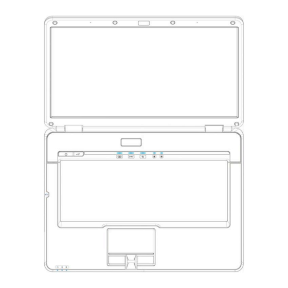
JHL90 Service Manual • Major Sub-assembly Specification • System interconnection (For JHL90) Top View Position Description Position Description MB_PCB F/P Board to MLB USB/Board Function Board to MLB K/B to MLB (25 PIN) Inverter Conn EXP-CARD CONN SPEAKER Conn SATA HDD CONN... -
Page 68: Bottom View
JHL90 Service Manual Bottom view Position Description Position Description RJ45 Audio Jack (black) ODD Conn D-sub FAN to MLB MDC Conn MXM Board Conn Mini PCI Express Conn (H=4.0mm) CPU SOCKET Mini PCI Express Conn (H=9.9mm) H5.2 DDRII 3 IN 1 CARD H9.2 DDRII... - Page 69 Chapter 4 DC-DC Converter...
- Page 71 OVER Current protection:..............4-8 OVER Voltage protection:..............4-9 Under voltage protection:...............4-9 Short circuit protection: ..............4-9 3.10 I/O....................4-9 3.11 BATTERY ..................4-10 4. INVERTER SPECIFICATION JHL90/91 15.4 inch inverter spec ..4-12 Features ..................4-12 Absolute maximum rating ............4-12 Electrical characteristic ..............4-13 Electrical specification ..............4-15 Connector description..............4-15 Safety Protection .................4-16...
-
Page 73: Chapter 4 Dc-Dc Converter
• 6 cells Li-Ion 18650 size smart battery Pack with 53.28Wh capacity • 6 cells Li-Ion 18650 size smart battery Pack with 57.72Wh capacity • 9 cells Li-Ion 18650 size smart battery Pack with 79.92Wh capacity DC-DC CONVERTER JHL90/91 Series Power System block diagram DC/DC 90W/65W ADAPTER +5VALWP... -
Page 74: Jhl90 Adapter Description
JHL90 Service Manual JHL90 Adapter Description This specification defines the performance and characterist ic of 90W AC adapter power supply. It supplies a constant voltage 19V output source for JHL90 series no ebook computer. ature • Accepts universal input from 90V AC to 264V AC •... -
Page 75: Dc-Dc Converter
JHL90 Service Manual DC-DC CONVERTER Description The DC-DC converter is designed to s upply the power for JHL90 series notebook computer of Compal. It supply +5 VALWP, +3VALWP, +1.8VP, +1.5VP, +1.05VSP, +0.9VSP, +VGA_COREP, VG A_1.8VSP for logical system, + CPU_CORE for CPU and supplies for the built-in KB926 microprocessor which handles the keyboard and PMU control functions of the system. - Page 76 JHL90 Service Manual Total regulation 5V±5% depend on VCC static VGA_COREP±5% and Transient Tolerance-- Ripple voltage 100mVp-p max 20mVp-p max@36A 60mVp-p max Item +0.9VSP +3VALWP +1.05VSP nominal voltage +0.9V +3.3V +1.05V Min. current Max. current 1.4A 5.5A 8.16A Peak current 7.85A...
- Page 77 JHL90 Service Manual 1.3500 1.3375 1.3250 1.3125 1.3000 1.2875 1.2750 1.2625 1.2500 1.2375 1.2250 1.2125 1.2000 1.1875 1.1750 1.1625 1.1500 1.1375 1.1250 1.1125 1.1000 1.0875 1.164V 1.0750 1.0625 1.0500 1.0375 1.0250 1.0125 1.0000 0.9875 0.9750 0.9625 0.9500 0.9375 0.9250 0.9125...
- Page 78 JHL90 Service Manual 0.8875 0.8750 0.8625 0.8500 0.8375 0.8250 0.8125 0.8000 0.7875 0.7750 0.7625 0.7500 0.7375 0.7250 0.7125 0.7000 0.6875 0.6750 0.6650 0.6500 0.6375 0.6250 0.6125 0.6000 0.5875 0.5750 0.5625 0.5500 0.5375 0.5250 0.5125 0.5000 0.4875 0.4750 0.4625 0.4500 0.4375...
- Page 79 JHL90 Service Manual 0.4250 0.4125 0.4000 0.3875 0.3750 0.3625 0.3500 0.3375 0.3250 0.3125 0.3000 0.2875 0.2750 0.2625 0.2500 0.2375 0.2250 0.2125 0.2000 0.1875 0.1750 0.1625 0.1500 0.1375 0.1250 0.1125 0.1000 0.8750 0.7500 0.6250 0.5000 0.3750 0.2500 0.1250...
-
Page 80: Charger
JHL90 Service Manual Charger • Controlled by KB926 microprocessor from motherboard • Temperature sense capability for the battery (charge active between 0°C ~ 40°C) • Fast charge current 3Amps (max.) for Li-Ion Battery at system off, approach 25W fast charge at system ON. (depend on system load) •... -
Page 81: Over Voltage Protection
JHL90 Service Manual OVER Voltage protection: • +5VALWP: 5V +00mV of programmed VID level • +1.8VP: 1.8V + (113% ~ 119%) • +1.5VSP: 1.5V + (113% ~ 119%) • +1.05VSP: 1.05V + (113% ~ 119%) • +VGA_Corep: VGA_Corep* (113% ~ 119%) •... -
Page 82: Battery
JHL90 Service Manual 3.10.3 Interface between Power with M/B DC/DC Signals Voltage Description Level SUSP# 0~3.3V Low Active, system suspend control signal 51ON# 0~floating Low Active, POWER ON control signal. FSTCHG 0~3.3V High Active, ENE926 use this pin to control the fast charge of charge... - Page 83 JHL90 Service Manual Battery Configuration 3S2P 3S2P 3S3P Battery Nominal Voltage 11.1 11.1 11.1 Single Cell Chemistry Li-ion Li-ion Li-ion Single Cell Type 18650 18650 18650 Single Cell Capacity 2400 2600 2400 (mAH) Dumb/Smart Battery Smart Battery Smart Battery Smart Battery (SMBus ver.
-
Page 84: Inverter Specification Jhl90/91 15.4 Inch Inverter Spec
JHL90/91 15.4 inch inverter spec Description This inverter is designed to light up the CCFL of LCD for JHL90/91 notebook. This inverter is designed to light up the CCFL of LCD for notebook. It should be supported JHL90/91 15.4 LCD panels. There are two control signals that come from system to control lamp brightness. -
Page 85: Electrical Characteristic
JHL90 Service Manual Storage temperature: - 20°C ~ 70°C Humidity: 0 ~ 90% without condensation MTBF: MIN 50000 hours. (In Compal system) Electrical characteristic Item Symbol Min. Typ. Max. Unit Comment 7.5V (continuous) can work Input voltage INV_PWR 14.8 *Note 1 Input current 0.33... - Page 86 JHL90 Service Manual Turn off 150Vp- voltage Voff PWM=30% (Low side) Voltage Rise Trise 300us PWM=30% time (Low side) Voltage fall time (Low Tfall 300us PWM=30% side) Notes: • The inverter can work in 7.5V input voltae (continuous), but 7.5V electronic characteristic will not be care.
-
Page 87: Electrical Specification
JHL90 Service Manual Electrical specification 4.4.1 Electrical specification Symbol Min. Typ. Max. Unit Comment Vrms Lamp operating voltage (650+/-50) oper mArms DAC_BRIG: 0 V, PWM: 100% mArms DAC_BRIG: 0 V, PWM:30% mArms DAC_BRIG: 1 V, PWM: 100% mArms DAC_BRIG: 1 V, PWM:30% η... -
Page 88: Safety Protection
JHL90 Service Manual Symbol Description Connected to high voltage of LCD lamp Connected to low voltage of LCD lamp Note: Please mark “CAUTION HIGH VOLTAGE” around CN2 Safety Protection 4.6.1 Open lamp protection: When inverter is on open lamp status, any component on inverter should be O.K and inverter is no damaged, no fire and no arcing. -
Page 89: Reliability Requirements
JHL90 Service Manual Reliability Requirements Mean Time Between Failures (MTBF) • 17,000 hours with 90% confidence level. Reference Document Electro-Static Discharge (ESD) Performance Criteria No soft error Air Discharge +/- 10KV Contact Discharge +/- 5KV Regulatory Compliance UL 60950-1 Standard for safety of Information Technology Equipment including Electrical Business Equipment. - Page 90 JHL90 Service Manual CSA C108.8 Electromagnetic Emission from Data Processing Equipment and Electronic Office Machines. Council directive of 3 May 1989 on the approximation of the EMC Directive (89/336/EEC) laws of Member States relating to electromagnetic compatibility. AS/NZS 3548 Limits and methods of measurement of radio interference characteristics of information technology equipment.
-
Page 91: Power Interface
JHL90 Service Manual Power interface Power requirement Voltage Ripple / Load Control Noise Item Description Tolerance Remark signal Min. Max. Peak Normal By VID CPU spec. CPU spec. VR_ON +CPU_CORE control +0.9VS 0.75A 0.9V SUSP +1.05VS 1.05V SUSP +1.5VS 1.5V SYSON 1.8V... -
Page 92: Power Sequence
JHL90 Service Manual Power Sequence 7.3.1 AC exist 4-20... - Page 93 JHL90 Service Manual 7.3.2 Suspend/Resume Sequence 4-21...
- Page 94 JHL90 Service Manual Time Table Item Min. Max. Control Spec. List ICH9 output 11450/Figure19-21, Table19-20, T173 50ns ICH9 output 11450/Figure19-21, Table19-21, T181 110ms ICH9 output 11450/Figure19-21, Table19-21, T182 110ms ICH9 output 11450/Figure19-21, Table19-21, T183 10ms 40ms EC control, SYSON active to SUSP# active time.
-
Page 95: Reset Map
JHL90 Service Manual Reset Map +2.5V +1.5VS/+3VS/1.2VS PCIRST# CH7011 GATE PCIRST# CBRST# CBRST# MGCH IEEE1394 TSB43AB21 SYS_PWROK SYS_PWROK PCIRST# PCIRST# ICH_VGATE H_RESET# GATE VGATE CK408_PWRGD# _CPUCOR CBRST# S1_RST# Slot-S1 +3VALW/+1.5VALW +3V V /+1.5 +3VS/+1.5VS CardBus +CPU_CORE PCIRST# OZ6933 S2_RST# Slot-S2... -
Page 96: Pci Resource Assignment
JHL90 Service Manual PCI resource assignment North Bridge- GMCH • Bus 0, Device 0, Function 0: Host-Hub interface bridge/DRAM controller • Bus 0, Device 1, Function 0: Host-AGP bridge South Bridge- ICH9 • Bus 0, Device 31, Function 0: PCI-LPC bridge •... -
Page 97: Ec Smbus Block
JHL90 Service Manual 10. EC SMBus Block +5VS +5VALW 2N7002 Thermal Sensor OZ168 EMC1402 ADM1032AR R363 R364 2N7002 4.7K_0402_5% 4.7K_0402_5% R432 R433 100K_0402_5% 100K_0402_5% +5VCD EC_SMD2 SM-BUS 2 EC_SMC2 SM-BUS 1 EC_SMC1 EC_SMD1 +5VALW +5VALW +5VALW R381 R382 4.7K_0402_5% 4.7K_0402_5%... - Page 99 Chapter 5 Disassembly Guide...
- Page 101 Contents Chap ter 5 Disassembly Guide Disassembling the Base Unit ..............5-1 Removing the Battery Pack ............5-2 Removing the HDD Module ............5-3 Removing the DDR RAM...............5-5 Disassembling the ODD (CD-ROM/DVD-ROM/CD-RW…) ...5-7 Removing the Keyboard ..............5-9 Removing the Power Board............5-12 Removing the Function Board .............5-13 Removing the Bluetooth Module..........5-14 Removing the TV Tuner Card ............5-15...
-
Page 103: Disassembling The Base Unit
JHL90 Service Manual Disassembling the Base Unit These are the directions for disassembling the base un it. You will need a 5.5mm Nut Driver, a medium size screwdriv These directions are to disassemble the complete unit and are cross- referenced to Chapter 6 for the replacement of component parts. -
Page 104: Removing The Battery Pack
JHL90 Service Manual Removing the Battery Pack To remove the battery pack from the battery bay, follow the steps below: 1. Turn the notebook upside down. 2. Slide the right battery release lock in the direction of the arrow to unlock the battery pack. -
Page 105: Removing The Hdd Module
JHL90 Service Manual Removing the HDD Module Follow the steps below to remove the HDD module 1. Turn the notebook upside down. 2. Remove the two screws securing the HDD compartment cover. 3. Pull up the HDD compartment cover in the direction of the arrow. - Page 106 JHL90 Service Manual 4. Remove the two screws securing the HDD module in place. 5. Pull the tab to remove the HDD module in the direction of the arrow. 6. Remove the four silver screws to take off the HDD case.
-
Page 107: Removing The Ddr Ram
JHL90 Service Manual Removing the DDR RAM Follow the steps below to remove the DDR RAM: 1. Turn the notebook upside down. 2. Remove one screw securing the RAM cover and then remove the cover. 3. Push the latches to release the RAM module. A spring will force one end of... - Page 108 JHL90 Service Manual 4. Grasp the module and pull it out.
-
Page 109: Disassembling The Odd (Cd-Rom/Dvd-Rom/Cd-Rw
JHL90 Service Manual Disassembling the ODD (CD-ROM/DVD-ROM/CD-RW…) Follow the steps below to disassemble the optical drive (ODD): 1. Turn the notebook upside down. 2. Remove three screws securing and remove the thermal cover upward. 3. Remove the screw and insert a flat screwdriver into the slot as shown and... - Page 110 JHL90 Service Manual 4. Remove two screws from the bracket plate, and then remove the bracket plate.
-
Page 111: Removing The Keyboard
JHL90 Service Manual Removing the Keyboard en the display panel and follow the steps below to remove the keyboard. 1. Turn the notebook upside down than remove three screws. 2. Between the keyboard and cover insert a screw driver then Lift up the strip... - Page 112 JHL90 Service Manual 3. Remove 3 screws securing the keyboard. 4. Turn over the keyboard, revealing the keyboard cable underneath. 5-10...
- Page 113 JHL90 Service Manual 5. Use a thin tool such as a screwdriver to lever up the connector bracket and disconnect the keyboard cable from the motherboard. 6. Lift and remove the keyboard. 5-11...
-
Page 114: Removing The Power Board
JHL90 Service Manual Removing the Power Board To remove the LCD module, first remove the keyboard. Then follow the steps below: 1. Remove two screws securing the power board to the logic upper. 2. Disconnect the power board cable as shown and remove the power board. -
Page 115: Removing The Function Board
JHL90 Service Manual Removing the Function Board To remove the front board, first remove the logic upper as described in the preceding sections. Then follow the steps below: 1. Remove three screws securing the Function board to the logic upper. -
Page 116: Removing The Bluetooth Module
JHL90 Service Manual Removing the Bluetooth Module To remove the Bluetooth module, first remove the keyboard. Then follow the steps below: 1. Remove one screw securing the Bluetooth module to the logic upper. 2. Disconnect the Bluetooth cable and remove the Bluetooth module. -
Page 117: Removing The Tv Tuner Card
JHL90 Service Manual Removing the TV Tuner Card To remove the TV tuner card, follow the steps below: 1. Disconnect the TV tuner card. 2. Remove two screws securing the TV tuner card and cable to the motherboard. 5-15... - Page 118 JHL90 Service Manual 3. Then remove the TV card and remove cable. 5-16...
-
Page 119: Removing The Modem Card
JHL90 Service Manual 1.10 Removing the Modem card To remove the Modem card, follow the steps below: 1. Turn the notebook over. Remove two screws from the modem card. 2. Remove the Modem card and remove cable. CAUTION: Do not touch the connectors on the Modem card or on the computer. -
Page 120: Removing The System Fan
JHL90 Service Manual 1.11 Removing the System Fan To remove the system fan. Then follow the steps below: 1. Turn the notebook over. Remove three screws securing the system fan. 2. Disconnect the fan and lift out the system fan. -
Page 121: Removing The Thermal Module
JHL90 Service Manual 1.12 Removing the Thermal Module To remove the thermal module, first remove the Modem card. Then follow the steps below: 1. Turn the notebook over. Remove four spring screws securing the thermal module to the motherboard. 2. Lift and remove the thermal module from the motherboard. -
Page 122: Removing The Cpu
JHL90 Service Manual 1.13 Removing the CPU To remove the CPU, first remove the Modem card, and thermal module. Then follow the steps below: 1. Turn the cam on the CPU socket with a flat-blade screwdriver so that the notch on the cam is aligned with the open side of the CPU socket to unlock the CPU. -
Page 123: Removing The Lcd Module
JHL90 Service Manual 1.14 Removing the LCD Module To remove the LCD module, first remove the keyboard. Then follow the steps below: 1. Disconnect the L CD power (LVDS), CMOS, and microphone cables and pull the wireless and TV tuner card ante nnas free from the laptop as shown. - Page 124 JHL90 Service Manual 3. Turn the Notebook over remove two screws and LVDS cable. 4. Them remove all cable and LCD module. 5-22...
-
Page 125: Disassembling The Display And The Inverter Board
JHL90 Service Manual 1.15 Disassembling the Display and the Inverter Board To disassemble the display and inverter board, first remove the keyboard. Then follow these steps: 1. Remove six screw pads as shown. 2. Remove the six screws securing the LCD bezel to the LCD module. - Page 126 JHL90 Service Manual 3. Carefully insert your fingers between the display and the LCD bezel as indicated by the arrow, and gently pry up the LCD bezel. 4. Remove the five screws mounting the display, inverter board, and LVDS/CMOS cable to the LCD cover.
- Page 127 JHL90 Service Manual 5. Disconnect the two connectors on either side of the inverter board. Remove the inverter board. 6. Gently lift out the display. Remove eight screws securing the hinges to the display. 5-25...
- Page 128 JHL90 Service Manual 7. Detach the LVDS cable from the back of the LCD panel. 5-26...
-
Page 129: Removing The Camera Module
JHL90 Service Manual 1.16 Removing the Came ra Module To remove the camera module, first remove the keyboard, LCD module, LCD display, and inverter board. Then follow these steps: 1. Disconnect the CMOS cable from the camera module. 2. Remove four screws securing the camera module to the LCD cover. Remove the camera module. -
Page 130: Removing The Logic Upper
JHL90 Service Manual 1.17 Removing the Logic Upper To remove the logic upper, first remove the battery pack, HDD, memory module, ODD, keyboard, power board, wireless LAN, system fan, thermal module, CPU, Bluetooth module, and LCD module as described in the preceding secti ons. - Page 131 JHL90 Service Manual 3. Lift off the logic upper. 5-29...
-
Page 132: Removing The Motherboard
JHL90 Service Manual 1.18 Removing the Motherboard To remove the motherboard, first remove the logic upper, LED board and CIR board as described in the preceding sections. Then follow the steps below: 1. Remove three screws securing the motherboard to the logic upper. -
Page 133: Removing The Vga Board
JHL90 Service Manual 1.19 Removing the VGA Board To remove the VGA board, first remov e the motherboard as described in the preceding sections. Then follow the steps below: 1. Remove four spring screws securing the VGA heat sink to the VGA board. - Page 134 JHL90 Service Manual 3. Remove the two M2.5x3 screws securing the VGA board to the motherboard. 4. Remove the VGA board. 5-32...
-
Page 135: Removing The Cir
JHL90 Service Manual 1.20 Removing the CIR 1. Remove one screw from the CIR. .21 Removing the USB Board To remove the logic upper, LED board, and motherboard as described in the preceding sections. Then follow the steps below: 1. Remove the USB board, and then remove one screw, TV card cable and svideo-in cable. -
Page 136: Removing The Rj11 Cable
JHL90 Service Manual 1.22 Removing the RJ11 Cable To remove the RJ11 Cable, first remove the logic upper, LED board, and motherboard as described in the preceding sections. Then follow the steps below 1. Lift the RJ11 Cable from its housing and detac h the cable to remove it from the logic upper. -
Page 137: Removing The Fingerprinter Module
JHL90 Service Manual 1.23 Removing the Fingerprinter Module To remove the fingerprinter module, first remove the logic upper as described in the preceding sections. Then follow the steps below: 1. Remove the screw securing the fingerprinter module to the rear side of the logic upper. -
Page 138: Removing The Touch Pad
JHL90 Service Manual 1.24 Removing the Touch Pad To remove the touch pad board, first remove the logic upper as described in the preceding sections. Then follow the steps below: 1. Remove one screw securing the touch pad to the rear side of the logic upper. - Page 139 Chapter 6 Testing and Troubleshooting...
- Page 141 Contents Chap ter 6 Testing and Troubleshooting PERFORM VISUAL INSPECTION ............6- Troubleshooting Flowchart..............Power Supply Troubleshooting ............... 6-5 Procedure 1 Power Status Check ..........6-6 Procedure 2 Adaptor / battery replacement ........Procedure 3 Power supply connection check ........6-7 Procedure 4 Diagnostic check ......
- Page 142 11.1 Procedure 1 Audio CD check .............6-26 .2 Procedure 2 Drive cleaning check ..........6-26 .3 Procedure 3 Software check............6-26 11.4 Proced ure 4 Diagnostic test............6-26 .5 Procedure 5 Connection check and replacement check....6-26 12. Modem Troubleshooting ................6-28 12.1 Procedure 1 Telephone line connection check ......6-29 12.2 Procedure 2 Modem card connection check........6-29 12.3 Procedure 3 Modem replacement check ........6-29 13.
-
Page 143: Perform Visual Inspection
JHL90 Service Manual The purpose of this chapter is to provide a systematic method of isolating problems you may have with the JHL90 series Notebook Computer. We assume that you have a basic understanding of DOS-based computer systems as well as knowledge of standard troubleshooting procedures. - Page 144 JHL90 Service Manual START Connect the AC adapter to the DC-IN socket Perform the Power Supply Troubleshootin g procedures in Is the DC-IN LED on? section 6-2 Perform the Power Supply Troubleshooting procedur es in Is the Battery LED on?
- Page 145 JHL90 Service Manual Perform the keyboard Does typed characters appear correctly? Troublesh ooting procedures in section 6-5 Insert the diagnostics disk into FDD. Then run the diagnostics test program. Perform the FDD Troubleshooting procedures Is the diagnostics test loaded? in section 6-4...
- Page 146 JHL90 Service Manual If the diagnostics program cannot detect an error, the problem may be intermitten The test program should be executed several times to isolate the problem. When problem has been located, perform the appropriate troubleshooting procedures as follows: •...
-
Page 147: Power Supply Troubleshooting
JHL90 Service Manual Power Supply Troubleshooting START Check Power Supply Status (Procedure 1) Replace adaptor / battery Are the DC-IN and (Procedure 2) Battery LEDs lit? Check powe r supply nnections (Procedure 3) Run diagnostic p rogram Can you turn the... - Page 148 JHL90 Service Manual The power supply controls many functions and components. To determine if the power sup ply is functioning properly, start with Procedure 1 and continue with the other P rocedures as instructed. The flowchart in Figure 6-2 gives a summary of the process.
-
Page 149: Procedure 3 Power Supply Connection Check
JHL90 Service Manual JHL90 Service Manual Table 2-2 POWER LE Power supply status POWER LED System Power On (LED is solid blue). blue Solid on System Suspended Blue blinking System Power Off. To check the power supply status, install a battery pack and connect an AC adaptor to the DC-IN port on the compute r and to a power supply. -
Page 150: Procedure 4 Diagnostic Check
JHL90 Service Manual Any of the connectors may be disconnected. Perf orm Check 1. Check 1 Disconnect the AC power cord from wall outlet. Check the power cable for breaks. • If the power cord is damaged, connect a new AC power cord. -
Page 151: Procedure 5 Replacement Check
JHL90 Service Manual Procedure 5 Replacement check The system board may be disconnected or damaged. Disassemble the comp uter following the steps described Replacement Proced ures . Check the connection between the AC adaptor and the system board. After checking the connection,... -
Page 152: Display Troubleshooting
JHL90 Service Manual JHL90 Service Manual Display Troubleshooting START Perform external display cheek (Procedure 1) Does the external display function ok? Perform diagnostic check (Procedure 2) Display is not faulty. Continue Was a display problem troubleshooting detected? refer to Figure 2.1... -
Page 153: Procedure 1 External Display Check
JHL90 Service Manual This section describes how to determine if the compu ter’s display is functioning properly. The process is outlined in Figure 6-3. Start with Procedure 1 and continue with the other procedures as instructed. • Procedure 1: External display check •... - Page 154 JHL90 Service Manual Check 3 Replace the LCD module with a new one and test display again. • If the problem still exists, perform Check 4. Check 4 Replace the LCD/FL cable with a new one and test disp lay again.
-
Page 155: Keyboard Troubleshooting
JHL90 Service Manual Keyboard Troubleshooting START Perform external keyboard cheek (Procedure 1) Does the external keyboard function Perform diagnostic check (Procedure 2) Keyboard is not faulty. Continue Was a keyboard problem troubleshooting detected? refer to Figure 2.1 Perform connector and... -
Page 156: Procedure 1 External Keyboard Check
JHL90 Service Manual To determine if the computer’s keyboard is functioning properly, perform the following procedures. Figure 6-5 outlines the process. Start with Procedure 1 a continue with the other procedures as ins tructed. • Procedure 1: External keyboard check •... -
Page 157: External Usb Devices Troubleshooting
JHL90 Service Manual External USB Devices Troubleshooting START Perform external device and connection check (Procedure 1) Does the device function Check USB port when connected to a connection different USB port? Original USB Does an alternative USB device is faulty... -
Page 158: Procedure 1 External Device And Connection Check
JHL90 Service Manual To determine if the computer’s external USB devices are functioning properly perform the following procedures. Figure 6-5 outlines the process. Start with Procedure 1 and continu e as instructed. • Procedure 1: External device and con nection check •... -
Page 159: Crt Troubleshooting
JHL90 Service Manual CRT troubleshooting START Perform CRT connection check (Procedure 1) Replace CRT Does replace CRT cable cable function property? Perform CRT set check (Procedure 2) Use different CRT functioning CRT set Replace system board Figure 6-6 CRT troubleshooting process... -
Page 160: Procedure 1 Crt Connection Check
JHL90 Service Manual To determine if the computer’s CRT port is functioning properly, perform the following procedures. Figure 6-6 outlines the process. Start with Procedure 1 and continue as instructed. • Procedure 1: CRT connection check • Procedure 2: CRT set check... -
Page 161: Hdmi Troubleshooting
JHL90 Service Manual HDMI troubleshooting START Perform HDMI connection check (Procedure 1) Replace HDMI Does replace HDMI cable cable function property? Perform HDMI set check (Procedure 2) Use different HDMI functioning HDMI set Replace system board Figure 6-7 HDMI troubleshooting process... -
Page 162: Procedure 1 Hdmi Connection Check
JHL90 Service Manual To determine if the computer’s HDMI port is functioning properly, perform the following procedures. Figure 6-7 outlines the process. Start with Procedure 1 a continue as instructed. • Procedure 1: HDMI connection check • Procedure 2: HDMI set check... -
Page 163: Touch Pad Troubleshooting
JHL90 Service Manual Touch Pad Troubleshooting START Touch Pad connection check (Procedure 1) Touch Pad replacement check (Procedure 2) Replace system board Figure 6-8 Touch Pad troubleshooting process 6-21... -
Page 164: Procedure 1 Touch Pad Connection Check
JHL90 Service Manual To determine if the computer’s built-in Touch Pad is functioning properly, perform the following procedures. Figure 6-8 outlines the process. Start with Procedure 1 and continue as instructed. • Procedure 1: Touch Pad connection check • Procedure 2:... -
Page 165: Speaker Troubleshooting
JHL90 Service Manual 10. Speaker Troubleshooting START Perform audio source test (Procedure 1) Speakers are not faulty. Continue Do all sources have troubleshooting - same problem? see Figure 2-1 Perform earphone test (Procedure 2) Do earphones function correctly? Perform connection... -
Page 166: Procedure 1 Audio Source Test
JHL90 Service Manual To determine if the computer’s built-in speakers are functioning properly, perform the following procedures. Figure 6-9 outlines the process. First adjust the speaker volume to an appropriate level. Start with Procedure 1 and continue as instructed. • Procedure 1: Audio source test •... -
Page 167: Cd-Rom/Dvd Troubleshooting
JHL90 Service Manual 11. CD-ROM/DVD Troubleshooting START Perform audio CD check (Procedure I) Perform drive- cleaning check Audio CD functions ok? (Procedure 2) Perform software check (Procedure 3) Perform diagnostic test (Procedure 4) Perform connection and replacement check (Procedure 5) -
Page 168: Procedure 1 Audio Cd Check
JHL90 Service Manual This section describes how to determine if the computer’s internal DVD-ROM drive or CD-RW/DVD-ROM drive is functioni ng properly. Figure 6-10 outlines the process. Perform the steps below starting with Procedure 1 and continue with the other procedures as required. - Page 169 JHL90 Service Manual Check 2 The drive or drive cable may be defective or damaged. Replacement Procedures. • If the drive is still not functioning properly, perform Check 3. Check 3 The system board m ay be dam aged. 6-27...
-
Page 170: Modem Troubleshooting
JHL90 Service Manual 12. Modem Troubleshooting START Perform telephone line connection check (Procedure 1) Check / replace Computer unable to telephone line and detect telephone connections signal? Perform connection check (Procedure 2) Perform replacement check (Procedure 3) Replace system board... -
Page 171: Procedure 1 Telephone Line Connection Check
JHL90 Service Manual This section describes how to determine if the computer’s modem is functioning properly. Figure 6-11 outlines the process. Perform the steps below starting wi Procedure 1 and continuing with the other procedures as required. • Procedure 1:... -
Page 172: Express Card Troubleshooting
JHL90 Service Manual 13. Express card Troubleshooting START Perform express card test (procedure 1) Do errors occur Express card unit during express is not faulty card test? Perform express card socket replacement check (Procedure 2) Replace system board Figure 6-12 Express card troubleshooting process... -
Page 173: Procedure 1 Express Card Test
JHL90 Service Manual This section describes how to determine if the express card player is functioning properly. The process is summarized in Figure 6-12. Perform the steps below starting with Procedure 1 and continuing with the other procedures as requi red. -
Page 174: Wireless Lan Troubleshooting
JHL90 Service Manual 14. Wireless LAN Troubleshooting START Perform diagnostic test (Procedure 1) Wireless LAN Was an wireless LAN problem dejected? system is not faulty. Perform connector and replacement check (Procedure 2) Replace wireless LAN antenna/unit Replace system board Figure 6-13 Wireless LAN troubleshooting process... -
Page 175: Procedure 1 Diagnostic Test
JHL90 Service Manual The wireless LAN antenna wire, wireless LAN unit or system board may each be the source of a wireless LAN fault. Any of these components may be damaged. to determine if the computer’s wireless LAN system is functioning properly, perform the following procedures. - Page 176 JHL90 Service Manual Check 3 The wireless LAN unit may be damaged. Replace it with a new one following the instructions in Chapter 4. • If the problem still exists, perform Check 4. Check 4 The system board may be damaged. Replace it with a new one following the instructions in Chapter.
Need help?
Do you have a question about the JHL90 and is the answer not in the manual?
Questions and answers