Table of Contents
Advertisement
Quick Links
Advertisement
Table of Contents

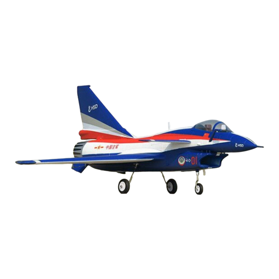
Summary of Contents for HSD J10
- Page 1 10 5mm...
-
Page 2: Safety Precautions And Warnings
Each product from HSD has unique functions that users will need to fully grasp step by step, as the assembly will be completed by you. -
Page 3: Table Of Contents
C O N T E N T S A t t e n t i o n ................0 1 Box Contents..................01 Landing Gear System..............02 Assembly... -
Page 4: Box Contents
ATTENTION: EDF jets require Li-PO batteries with a high discharge rating (Crating) for increased safety and optimal performance. We recommend using Li-Po batteries with a minimum of 40C or above. For 8S systems that require two batteries in series, the C rating must remain the same on both batteries for better consistency and performance. -
Page 5: Landing Gear System
LANDING GEAR SYSTEM: Hatch:standby port for single action Canard Throw Adjustment Canard Mixed controller Input:7.5V Airbrake Elevator Aileron Pilot lamp Manual operation button... -
Page 6: Assembly
ASSEMBLY 1. Install the canards by placing them over the control rod and securing it in place with the provided screws (PM3x5mm). Repeat this step for the other side. PM ×5mm Cockpit can be removed by pressing the sides and lifting up towards the front end. BALANCE OF CANARD MUST BE CONSISTENT 2.1.Insert the wing spar into one of the main wings. - Page 7 3.Install the ventral fin mounts with the glue as shown (omit if pre-installed). Repeat this step for the other side. After the ventral fin mounts are glued, install the ventral fins with the provided screws. 4.Glue the tail exhaust nozzle piece as shown below. First, apply the foam-safe adhesive within the inner slotted area of the rear exhaust exit as shown in the first figure.
- Page 8 6.Glue the J-10 Pitot Tube on the nose cone as shown below. After, apply adhesive to the inner edges of the nose cone and proceed to install it on the nose of the aircraft. 7.Glue the fuel filler pipe onto the right side of the fuselage as shown below. After, turn over the model and glue the antennas in their respective locations on the fuselage.
-
Page 9: A S S E M B L Y O F T H E F I X E D L A N D I N G G E A R
Assembly of the Fixed Landing Gears The J-10 PNP version, as produced by HSD Ltd., can be equipped with fixed landing gears to meet the preferences of certain pilots. When the fixed landing gears are used, the overall all-up weight (AUW) of the aircraft is reduced by the removal of the e-retract system. The fixed landing... -
Page 10: C O N T R O L H O R N A N D S E R V O A R M S E T T I N G
Control Horn and Servo Arm Settings The table to the right shows the factory settings for the Horns Arms control horns and servo arms. Fly the aircraft at factory settings before making changes. After flying ,you may choose to adjust the linkage positions for the desired control response. -
Page 11: Control Direction Tests
Control Direction Tests Assemble the aircraft and bind your transmitter to the receiver before performing this test. After binding a transmitter to the aircraft receiver, set the trims and sub-trims to 0,then adjust the clevises to center the control surfaces. Move the controls on the transmitter to make sure the aircraft control surfaces move in the proper direction. -
Page 12: Manual Settings
Manual settings When experiencing problems with the e-retracts, please refer to the Battery link method following steps: ATTENTION: a.Power on the system and press the button on the control box as shown. Connect the black (negative) anti-spark connectors first, b.Set the landing gears down with the manual button switch and and the red anti-spark connectors after. -
Page 13: Accessories
Accessories HS D A 02- 0 1 HSD A 0 2-0 2 H SDA 0 2 -03 HS D A 02- 0 4 HS D A 02- 0 5 HSD A 0 2-0 6 H SDA 0 2 -07 HSDA 0 2-08... -
Page 14: Accessories
Accessories HS D A 02- 2 1 HSD A 0 2-2 2 H SDA 0 2 -23 HS D A 02- 2 4 HS D A 02- 2 5 HSD A 0 2-2 6 H SDA 0 2 -27 HSDA 0 2-28... -
Page 15: Troubleshooting
TROUBLESHOOTING Problem Cause Solution 1. Charge the batteries 1.Battery is not fully charged 2.Install a fully charged battery 2.Transmitter battery low 3.Check for connection between the 3.Motors not connected ESC and Motor does 4.Replace motor 4.The motor is damaged not turn 5.Consult Radio manual and 5.Reciever is not bound to Tx through bind procedure again... -
Page 16: Model Flying Precautions
MODEL FLYING PRECAUTIONS - Select your flight area carefully. Always choose an open space that is unobstructed from trees and buildings and away from crowed area.Avoid flying in area with roads,electric/telephone poles/wires and water near by or within close proximity to full size air traffic. - Do not fly this model in poor weather.High winds,low visibility,inclement temperatures,rain and storms are to be avoided. - Page 17 10 5mm Distributed by: Banana Hobby California,USA Call or Text(626) 629-8243 WWW.bananaHobby.com...


Need help?
Do you have a question about the J10 and is the answer not in the manual?
Questions and answers