
Related Manuals for elco AEROTOP T


Summary of Contents for elco AEROTOP T
- Page 1 User Manual For Authorized Service Technicians AEROTOP T Air-Water Heat Pump with LOGON B WP61 12/2012 Art. 420010520000...
-
Page 2: Table Of Contents
Flexible Air Outlet............. Controller Unit Installation..........Special Conditions, Installation Location......Outdoor Installation Base/Pedestal Plan............Duct and Cable Bushing………........... 32 Controller Unit…………………………………………..AEROTOP T LOGON B WP61 Troubleshooting....Troubleshooting AEROTOP T Checklist............Initial Startup Sensor Characteristics NTC1, NTC10......System AEROTOP T07(C)-T16............. -
Page 3: Aerotop T
: • AEROTOP T07-T35 Model for outdoor installation • AEROTOP T..X With the right accessories the AEROTOP T are also suitable for • AEROTOP T..R outdoor installation (not T.. C..). • AEROTOP T..RX... -
Page 4: Basic Information
Basic information Legal guidelines Warranty conditions Receiving inspection General information In these cases it is necessary to pro- • The calculations, sizing, installa- vide a heating pipeline. A functional Warranty Conditions installations and putting into servi- heating or heat pump ready pose in Our performance guarantee shall lapse ce related to the products descri- according to the DIN EN 1264 should... -
Page 5: Aerotop T
AEROTOP T heat pump is especially Cascades with up to 4 heat pumps, or Thanks to the clever utilization of the efficient and a cost-saver. This heat... -
Page 6: Aerotop T
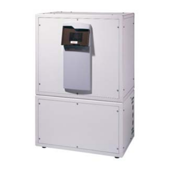
Product Description AEROTOP T Operating the heat pump is prohibited if Enclosure and Special Components Brief Description of the LOGON B The enclosure consists of a frame that the following conditions exist: WP61 Controller • is completely free of thermal bridging,... -
Page 7: Safety, Transport And Installation
• observed. AEROTOP T heat pumps can be • documents of the unit is installed on a level interior floor The accessories and additional mandatory. -
Page 8: Hydraulic Connections, Condensate Drain
Hydraulic Connections, Condensate Drain Heating System Hydraulic Dimensions Heater flow Ø 1” (T07-T16), Connections AEROTOP T heat pumps can be Ø 1 1/4” (T20-T35), connected in any desired layout. flexible. Heater return Ø 1” (T07-T16), The hydraulic connections require Ø 1 1/4” (T20-T35), flexible, flexible ducts to avoid noise trans- Condensate Drain Ø... -
Page 9: Aerotop
Electrical Connections General • Electrical Connections and Control An automatic cutout switch or a Information 3 phase, slow-blow fuse with The electrical connections must be neutral conductor must be provided established in compliance with local externally in compliance with the rules and regulations. -
Page 10: Unit Design, Terminal Assignment
Electrical Connections Unit Design, Terminal Assignment AEROTOP T..C.. Air out Air in Controller terminal assignment of components wired at the factory: Description RVS61 Slot RVS61 Output Low pressure High pressure Flow monitor consumer Condenser pump Process reversal valve Y22 Electrical heater element 1 flow Hot gas temperature sensor 1 Heat pump flow temp. -
Page 11: Electrical Connections
Electrical Connections Unit Design, Terminal Assignment AEROTOP T.. Air in Air out Flow sensor Return sensor Controller terminal assignment of components wired at the factory: Description RVS61 Slot RVS61 Output Low pressure High pressure Process reversal valve Y22 Electrical heater element 1 flow... - Page 12 Electrical Connections Unit Design, Terminal Assignment Air in Air out Flow sensor Return sensor Controller terminal assignment of components wired at the factory: Description RVS61 Slot RVS61 Output Low pressure High pressure Flow monitor consumer Electrical heater element 1 flow (only with AEROTOP T07 to T16) Process reversal valve Y22 Hot gas temperature sensor 1 Heat pump flow temp.
-
Page 13: Switch Box
Electrical Connection Switch box AEROTOP T..C ..6 Legenda: Terminal strip consumer, power Contactor electric heating element station blockage Main incoming supply 3*400V Terminal strip Fan Contactor / oil Fan fuse / control fuse (F3) sump heater Soft-starter and rotary current relay... -
Page 14: Electrical Connection
Electrical Connection Switch box AEROTOP T..CX Legenda: Terminal strip consumer, power Contactor electric heating element station blockage Main incoming supply 3*400V Terminal strip Fan Contactor / oil Fan fuse / control fuse (F3) sump heater Soft-starter and rotary current relay... - Page 15 Electrical Connection Switch box 4 5 8 Electrical Box AEROTOP TX e TRX with LOGON B WP61 Electrical Box AEROTOP T07-T16 with LOGON B WP61 Terminal block consumer (EC block / source flow Terminal block consumer (EC block / source flow monitor) monitor) Terminal block fuse fan / oil sump heater...
-
Page 16: Correct Installation Of An Air-Water Heat Pump
Checklist Correct Installation of an Air-Water Heat Pump AEROTOP T heat pumps are quiet Noise reduction measures considered and efficient. However, incorrectly early on in the development process integrating constructional components result in the fewest additional costs. may result in undesired noise in-... -
Page 17: Requirements, Parameterization, Upkeep
Requirements for Initial Startup The following persons must be Heat Pump Upkeep present to carry out the initial startup The AEROTOP T heat pump does not (Commissioning) The initial startup of the AEROTOP T process: require any special upkeep. However, heat pump must be carried out by our •... -
Page 18: Aerotop T
A Value B Value Fan Speed Settings The fan speed of the air-water 64 % 69 % T35(R) AEROTOP T heat pumps can be 56 % 61 % T32(R) directly adjusted on the LOGON B 72 % 77 % T26(R) WP61 controller (parameter 3010). -
Page 19: Aerotop T
5) Distance from wall: min 20 mm, max 40 mm Left corner setup Right corner setup Widt Dimensions Of Both Cutouts, Recommended Dimensions, Width Heigh Without Insulation Light Well AEROTOP T T07C, T07 1525 1200 T10C, T10 1095 1575 1050 1200 1000 T12C, T12, T14, T16... -
Page 20: Aerotop T
40 mm Dimensions With Dimensions Of Both Cutouts, Minimal Dimensions, Width Width Heigh Noise Dampers Without Insulation Light Well AEROTOP T T07C, T07 1525 1570 1225 635 1200 T10C, T10 1095 1575 1670 1325 1050 635 1200... -
Page 21: Corner Installation
Indoor Installation Corner Installation Installation Notes AEROTOP T07-T35 Insulate cutout with the self- adhesive insulation elements (2). The elements are cut to fit the size of the cutout opening. The width (400 mm) can be adjusted to match the wall thickness. Use a sharp knife to cut the elements to size. -
Page 22: Cutout Insulation Installation
Indoor Installation Cutout Insulation Installation Cutout Insulation The cutout insulation kit is needed to insulate the air intake and output cutouts. The kit includes the following: • 4 star screws • 4 insulating boards: Length and width dependent on heat pump size •... - Page 23 Indoor Installation Cutout Insulation Installation Fastening with Star Screws Use the star screws to additionally fix the insulation boards in place. One star screw per insulation element. Steps • Align in center of cutout insulation • Drill hole diameter is 8.5 Ø. •...
-
Page 24: Parallel Setup With Rigid Duct
T12C, T12, T14, T16 1200 1000 finished floor and completed walls/masonry. Rigid Duct Distance between Cutouts without Insulation Partition Wall Dimension Cutouts AEROTOP T k1 without k1 with partition partition Height k2 Width k3 wall wall T07C, T07 1500 1500... -
Page 25: Parallel Setup With Rigid Duct (With Noise Damper)
1200 1000 600 T20, T26 1400 1200 800 T32, T35 1400 1200 800 Rigid Duct Distance between Cutouts without Insulation Partition Wall Dimension Cutouts AEROTOP T k1 without k1 with Height Width partition partition wall wall T07C, T07 1500 1500... -
Page 26: General Duct Installation Information
Indoor Installation General Duct Installation Information The cause for condensate formation is The following factors promote the for- Condensate always collects at the due to the interplay between the room mation of condensate: coldest spots in a room. In our case, air temperature and the room's humidity this is the outgoing air side of the duct. - Page 27 Indoor Installation Flexible Intake • • Insulate cutout with the insulation Attach duct (5) to duct plates. elements (1). Adjust duct length if needed. Use • a wire cutter to shorten the duct. Attach intake box (2) to heat pump. •...
-
Page 28: Flexible Air Outlet
Indoor Installation Flexible Air Outlet 3, 2 • • Insulate cutout with the insulation Attach oval duct plate (3) to air elements (1). outlet panel. • • Attach air outlet panel (2) to heat Attach round duct plate (4) to wall. pump. -
Page 29: Controller Unit Installation
Indoor Installation Controller Unit Installation The controller unit is to be snapped into the provided opening of the controller panel. Then connect the ready-to-use cable to the controller unit. The controller panel with integrated control unit is pressed into the slot opening (1) at the heat pump enclo- sure. -
Page 30: Outdoor Installation (Not T
The condensate drain must The AEROTOP T heat pump is very be insulated and protected from frost quiet. However, since noise is per- and have a siphon with a min. height of ceived differently by different people, 100 mm routed into a closed drain. -
Page 31: Base/Pedestal Plan
A conduit (NW 250) must AEROTO T07-T16 be installed between building and heat pump for the installation lines (electrical, Min. 800mm hydraulic, and condensate). Setup Base/Pedestal AEROTOP T 1095 1195 Ø 175 1295 T12, T14, T16 1295 T20, T26... -
Page 32: Duct And Cable Bushing
Installation Duct and Cable Bushing Please take note of the base/pedestal Prepunched Opening for Outdoor plan with the required cutout. Installation of an Air-Water Heat The prepunched cover can be lifted Pump A prepunched opening (1) for the lines with a screwdriver or detached with routed from the rear of the enclosure sheet metal nippers. -
Page 33: Controller Unit
Installation Controller Unit The control unit must be mounthed on a internal wall Control unit (3), switch panel (1), of the building control unit bracket and Plexiglas unit cover (2) are supplied with Heat pump in the case of outdoor installa- tion. -
Page 34: Aerotop T Logon B Wp61 Troubleshooting
Troubleshooting/Fault Remedy AEROTOPT LOGON B WP61 Troubleshooting/Fault Remedy Problem Cause Remedy, Action 107: Hot gas compressor Hot gas temperature (B81) too high Not enough coolant Top off coolant Compressor leak Replace compressor Filter dryer dirty Check the difference in temperature between the filter drier inlet and outlet (∆T max = 3) Defective non-return valve Temperature at the compressor inlet and outlet is... - Page 35 Troubleshooting/Fault Remedy AEROTOPT LOGON B WP61 Troubleshooting/Fault Remedy Problem Cause Remedy, Action 225: Low pressure Low pressure problem problem Affects contact E9 at the LOGON B WP61. Low pressure switch in the cooling circuit triggered. Insufficient flow of air through evaporator A1 Ice formation A1 Check thawing function (check sensor) A2 Evaporator dirty...
- Page 36 Troubleshooting/Fault Remedy AEROTOPT LOGON B WP61 Troubleshooting/Fault Remedy Problem Cause Remedy, Action 12: PWW charge temp. The controller stores the potable water tempera- This parameter cannot be reset. If the minimum PWW charging HP too low ture at which the charging with the heat pump temperature is exceeded again the next time potable water is was last interrupted when the heat pump charged, the service function will also be reversed.
-
Page 37: Aerotop T Checklist
Initial Startup AEROTOP T Checklist System/Unit: Date: Task Check Comment Heat Pump Define hydraulic scheme, select and compare with system: Check hydraulic components Overflow valve installed (50% overflow), acc. to system scheme (systems with buffer storage and compact heat pump not required) -
Page 38: Initial Startup
Initial Startup AEROTOP T Checklist Task Check Comment No short-circuit / air intake and outlet next to each other No thermal and sound bridges Foamed insulation in cutout, no direct connection with wall Noise damper: Noise damper must be installed for AEROTOP T20 and later. - Page 39 System Sensor Characteristics NTC 1 k Sensor Characteristics NTC 10 k Sensor Characteristics 1K for Exterior Temperature Sensor B9 T [°C] R[Ohm] T [°C] R[Ohm] T [°C] R[Ohm] -30.0 13'034 2'857 30.0 -29.0 12'324 2'730 31.0 -28.0 11'657 2'610 32.0 -27.0 11'031 2'496...
-
Page 40: Technical Data
Hydraulic Connections R" 1” 1” 1” 1” 1” Water volume incl. connection hoses AEROTOP TC Water volume incl. connection hoses AEROTOP T Rated volume flow, heating nom/min 1500/568 2100/835 2700/999 3070/1171 3100/1300 Pressure loss, heating - AEROTOP TC (nom/min) 8.4/2.1 16.4/4.1... -
Page 41: Aerotop T20-T35
Material: Chrome steel AISI 316, 1.4401 Condenser, heater side Hydraulic connections Zoll 1¼” 1¼” 1¼” 1¼” Water content incl. connection hoses AEROTOP T Volume stream heating operation nom/min 3700/1714 5850/2259 6280/2803 7300/2964 Pressure loss heating operation 14.9/4.5 32.9/7.7 36.1/6.4 46.7/7... -
Page 42: Aerotop T07(C)X-T10(C)X
Material: chromium steel AISI 304 1.4301 Water Heat Exchanger Hydraulic Connections R" 1” 1” Water volume incl. connection hoses AEROTOP TC Water volume incl. connection hoses AEROTOP T Rated volume flow, heating (nom/min.) 1500/568 2100/835 Pressure loss, heating - AEROTOP TC (nom/min.) 8.4/2.1 16.4/4.1... -
Page 43: Aerotop T07R-T16R
Material: Chrome steel AISI 304, 1.4301 Condenser, heater side Hydraulic connections R" 1” 1” 1” 1” 1” Water content incl. connection hoses AEROTOP T Volume stream heating operation nom/min 1500/568 2100/835 2700/999 3070/1171 3100/1300 Pressure loss heating operation nom/min 28.3/4.4 32.9/4.1 33/4.5... -
Page 44: Aerotop T20R-T35R
Fuse WP Material: Chrome steel AISI 304, 1.4301 Condenser, heater side Hydraulic connections R" 1¼” 1¼” 1¼” 1¼” Water content incl. connection hoses AEROTOP T Volume stream heating operation nom/min 3700/1714 5850/2259 6280/2803 7300/2964 Pressure loss heating operation 14.9/4.5 32.9/7.7 36.1/6.4 46.7/7... -
Page 45: Aerotop T07Rx-T10Rx
Fuse WP with electrical insert: 6 kW Material: Chrome steel AISI 304, 1.4301 Condenser, heater side Hydraulic connections R" 1” 1” Water content incl. connection hoses AEROTOP T 1500/568 2100/835 Volume stream heating operation nom/min Pressure loss heating operation 28.3/4.4 32.9/4.1 Minimum volume stream cooling operation (∆t= 5 K) -
Page 46: Ec Declaration Of Conformity
Conformity Declaration EC DECLARATION OF CONFORMITY The manufacturer: Termogamma SA Address: declares that the following products: Air/Water Heat Pumps Types: meet the following guidelines and directives: EC Directives EC Pressure Equipment Directive EC Low Voltage Directive EC Electromagnetic Compatibility Directive Harmonized EN: Biasca, 2 October 2008 2 ottobre 2012... - Page 47 Conformity Declaration EC DECLARATION OF CONFORMITY The manufacturer: Termogamma SA Address: declares that the following products: Air/Water Heat Pumps Types: meet the following guidelines and directives: EC Directives EC Pressure Equipment Directive EC Low Voltage Directive EC Electromagnetic Compatibility Directive Harmonized EN: Biasca, 2 ottobre 2012 Management...
- Page 48 Conformity Declaration EC DECLARATION OF CONFORMITY The manufacturer: Termogamma SA Address: declares that the following products: Air/Water Heat Pumps Types: meet the following guidelines and directives: EC Directives EC Pressure Equipment Directive EC Low Voltage Directive EC Electromagnetic Compatibility Directive Harmonized EN: Biasca, 2 ottobre 2012 Management...
- Page 49 Conformity Declaration EC DECLARATION OF CONFORMITY The manufacturer: Termogamma SA Address: declares that the following products: Air/Water Heat Pumps Types: meet the following guidelines and directives: EC Directives EC Pressure Equipment Directive EC Low Voltage Directive EC Electromagnetic Compatibility Directive Harmonized EN: Biasca, 2 ottobre 2012 Management...
- Page 50 Conformity Declaration EC DECLARATION OF CONFORMITY The manufacturer: Termogamma SA Address: declares that the following products: Air/Water Heat Pumps Types: meet the following guidelines and directives: EC Directives EC Pressure Equipment Directive EC Low Voltage Directive EC Electromagnetic Compatibility Directive Harmonized EN: Biasca, 2 ottobre 2012 Management...
- Page 51 Notes...
- Page 52 Notes...
- Page 53 Notes...
- Page 54 ELCO GmbH Service: D - 64546 Mörfelden-Walldorf ELCO Austria GmbH A - 2544 Leobersdorf ELCOTHERM AG CH - 7324 Vilters ELCO-Rendamax B.V. NL - 1410 AB Naarden ELCO Belgium n.v./s.a. B - 1070 Anderlecht ELCO Italia S.p.A. I - 31023 Resana...
Need help?
Do you have a question about the AEROTOP T and is the answer not in the manual?
Questions and answers