Table of Contents
Advertisement
Planning Document
AEROTOP T
Air-Water Heat Pump
General information
•
Calculations, dimensioning, installations and commissioning
with regard to the products described in this document may only
be executed by proven experts.
•
Locally valid regulations must be observed; they may deviate
from the information in this document.
•
Changes remain reserved.
10/2012
Art. 420010415801
Advertisement
Table of Contents

Related Manuals for elco AEROTOP T Series


Summary of Contents for elco AEROTOP T Series
- Page 1 Planning Document AEROTOP T Air-Water Heat Pump General information • Calculations, dimensioning, installations and commissioning with regard to the products described in this document may only be executed by proven experts. • Locally valid regulations must be observed; they may deviate from the information in this document.
-
Page 2: Table Of Contents
Table of Contents Product overview AEROTOP T................Performance curves overview AEROTOP T at 35°C flow line..........AEROTOP T at 45°C flow line..........Product Description AEROTOP T................Planning hints Correct dimensioning..............Operational limits..............Determination of the heating capacity........Dimensioning of pressure expansion vessels......Dimensioning AEROTOP TC integrated expansion vessel.. -
Page 3: Aerotop T
Product Overview AEROTOP T The high quality air-water heat pump The reversible model of the AEROTOP T AEROTOP T extracts geothermal heat AEROTOP T heat pump series can The standard version is used from the environment and releases it also be used for active cooling. exclusively for heating, indoor or to the heating system at a higher The broad range of AEROTOP T heat... - Page 4 Performance Curves Overview AEROTOP T with 35°C Flow Heating capacity AEROTOP T with 35°C Flow Air intake temperature (°C) Also applies to same models in compact (C), in reversible (R), and mono-phase (M) designs.
- Page 5 Performance Curves Overview AEROTOP T with 45°C Flow Heating capacity AEROTOP T with 45°C Flow Air intake temperature (°C) Also applies to same models in compact (C), in reversible (R), and mono-phase (M) designs.
- Page 6 Product Description AEROTOP T High Degree of Efficiency and Cascade Flexible and Space-Saving Optimized Defrosting Thanks to the new heat pump controller Thanks to the clever utilization of the Thanks to the correspondingly LOGON B WP61, it is possible to link geometric properties of the radial fan, dimensioned air heat exchanger as well and operate several heat generators of...
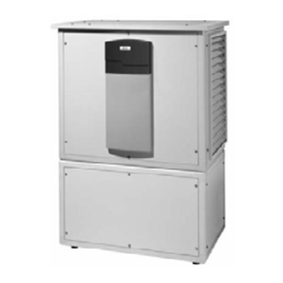
- Page 7 Product Description AEROTOP T Enclosure and Special Components Brief Description of the LOGON B The enclosure consists of a frame that WP61 Controller is completely free of thermal bridging, Plain text display unit, control and sound dampened, and specifically protection of the cooling circuit, defrost developed for use with heat pumps.
-
Page 8: Correct Dimensioning
Planning Notes Correct Dimensioning of the heating capacity Heat Demand and Heat Capacity The correct dimensioning of the air-water pump is a key task. The heat Heat demand of the building pump must meet the heat demand of the building. This demand increases as Heating capacity of the exterior temperature drops but the an air-water heat... -
Page 9: Aerotop T
Planning Notes Operating Limits General Information Pipes, tubes, and air ducts must be Area of Application The rated throughput values for kept as short as possible and routed in The following chart depicts the evaporator and condenser are such a way that pressure and heat loss application area of the air-water heat minimum values. - Page 10 Planning Notes Determining Heat Output and Allowances Oil heater Retrofitting an existing oil or gas heater with heat pump: With hot water Without hot water The heating capacity can be calculated Mid-level Qh = Oil consumption (Ltr.) Qh = Oil consumption (Ltr.) based on the existing average fuel altitude consumption.
- Page 11 Planning Notes Configuration of Pressure Expansion Vessels VN = VA x F x X Vn = Expansion volume VA = System content acc. to list below Temperature-dependent Factor TZ = Average system temperature TZ = (TV + TR)/2 40°C 50°C 60°C 80°C 0,0079...
- Page 12 Planning Notes Configuration of the AEROTOP TC integrated 12 litre expansion vessel General information for the correct Installation example Permissible water volume VA of the configuration AEROTOP T12C, electric heater system The heat pumps AEROTOP T..C can element with maximum capacity of The following table gives the maximum be installed without an additional 2 kW, standard...
- Page 13 Planning Notes Cooling with Heat Pump Systems Active Cooling Insulation for cold water must be The amount of sunlight received by The cooling energy is produced actively vapor-- proof and installed to all each room frequently differs due to using the heat pump to cool. The distributor system elements (pipes, the different cardinal points.
- Page 14 Planning Notes Cooling with Heat Pump Systems Comfortable Room Temperature A room is considered to be thermally comfortable when the room tempera- ture in the summer is below 28°C. This does not apply to air-conditioned rooms. Other factors are affecting thermal comfort ranges as well.
- Page 15 Planning Notes Cooling with Heat Pump Systems Monitoring Function to Prevent Distributor Box Condensate Precipitation To avoid condensation, the integrated Logon B WP61 controller features different monitor functions. 1. Flow Temperature Monitor The temperature is set at the factory to 18°C.
-
Page 16: Fan Rotational Speed
Technical Data AEROTOP T07(C)-T16 Heat pump type AEROTOP T T07(C) T10(C) T12(C) Heating operation For A2/W35 Heating Capacity 11.8 13.7 14.8 Power input Performance number EN14511 Heating operation For A7/W35 Heating Capacity 11.5 13.6 15.8 Power input Performance number EN14511 Condenser Scroll hermetically Maximum current consumption... - Page 17 Technical Data AEROTOP T20-T35 Heat pump type AEROTOP T Heating operation For A2/W35 Heating Capacity 18.9 24.4 30.2 33.4 Power input Performance number EN255 Heating operation for A7/W35 Heating Capacity 22.4 30.8 37.9 39.6 Power input Performance number EN255 Condenser Scroll hermetically Maximum current consumption lmax...
- Page 18 Technical Data AEROTOP T07(C)X-T10(C)X (available in F /I / B) Heat pump type AEROTOP T..X T07X (C) T10X (C) Heating operation For A2/W35 Heating Capacity Power input Performance number EN255 Heating operation for A7/W35 Heating Capacity 11.5 Power input Performance number EN255 Condenser Scroll hermetically Maximum current consumption...
- Page 19 Technical Data AEROTOP T07R-T16R Heat pump type AEROTOP TR T07R T10R T12R T14R T16R Heating operation For A2/W35 Heating Capacity 11.8 13.7 14.8 Power input Performance number EN14511 Heating operation for A7/W35 Heating Capacity 11.5 13.6 15.8 Power input Performance number EN14511 Cooling operation for A35/W18 Cooling Capacity...
- Page 20 Technical Data AEROTOP T20R-T35R Heat pump type AEROTOP TR T20R T26R T32R T35R Heating operation For A2/W35 Heating Capacity 18.9 24.4 30.2 34.4 Power input Performance number EN14511 Heating operation for A7/W35 Heating Capacity 22.4 30.8 37.9 39.6 Power input Performance number EN14511 Cooling operation for A35/W18...
- Page 21 Technical Data AEROTOP T07RX-T10RX (available in F /I / B) Heat pump type AEROTOP T..RX T07RX T10RX Heating operation For A2/W35 Heating Capacity Power input Performance number Heating operation for A7/W35 Heating Capacity 11.5 Power input Performance number Cooling operation for A35/W18 Cooling Capacity Power input...
- Page 22 Technical Data Fan Speed AEROTOP T A Value B Value Fan Speed Settings The fan speed of the air-water 64 % 69 % T35(R) AEROTOP T heat pumps can be 56 % 61 % directly adjusted on the LOGON B T32(R) WP61 controller (parameter 3010).
- Page 23 Technical Data Compact Heat Pump Water Heat Exchanger Pressure Loss The thermal mixing valve integrated Settings of the Integrated Thermal into the compact heat pump routes a Mixing Valve of the Compact Heat part of the flow water back to the Pumps accumulation tank at flow temperatures Important: Already provided with...
-
Page 24: Integrated Pumps
Technical Data Integrated pumps, compact heat pumps Heating pumps AEROTOP T07C/T07CX: GRUNDFOS Pumped Fluid = Water Delivery height Fluid Temperature = 20 °C Density = 998.2 kg/m AEROTOP T10C/T10CX/T12C: GRUNDFOS Pumped Fluid = Water Delivery height Fluid Temperature = 20 °C Density = 998.2 kg/m 977.8... -
Page 25: Remaining Pump Pressure
Technical Data Remaining pump pressure circulation pump Remaining pump pressure AEROTOP T07C Flow rate (l/h) Remaining pump pressure AEROTOP T10C Flow rate (l/h) Remaining pump pressure AEROTOP T12C Flow rate (l/h) -
Page 26: Noise Level
Sound AEROTOP T heat pumps Reduction table for sound: All ELCO-heat pumps are designed for This table can be used to estimate the noise level at the measuring location on the basis of the noise level at the emission location (noise level according to low-noise operation. - Page 27 Checklist Correct Installation of an Air-Water Heat Pump AEROTOP T heat pumps are quiet Noise reduction measures considered and efficient. However, incorrectly early on in the development process integrating constructional components result in the fewest additional costs. may result in undesired noise increases Subsequent measures usually are if the conditions are unfavorable.
- Page 28 Performance Data AEROTOP T07 – T16 (Information according to EN 14511) Serie Type Series AEROTOP T07 AEROTOP T10 AERO TO P T12 AERO TO P T 14 AERO TO P T16 CO P C OP CO P °C °C 12.2 18.3 19.5 23.0...
- Page 29 Performance Data AEROTOP T20 – T35 (Information according to EN 14511) Serie AEROTOP T20 AEROTOP T26 AEROTOP T32 AEROTOP T35 Type Series °C °C 27.5 37.1 45.8 48.6 10.6 25.3 34.7 42.9 44.7 10.2 23.1 32.4 40.0 40.8 21.7 29.9 36.8 38.4 19.7...
-
Page 30: Aerotop T07X – T10X
Performance Data AEROTOP T07X – T10X (Information according to EN 14511) S e rie A E R O T O P T0 7 X A E R O T O P T1 0 X Type Series C O P CO P °... - Page 31 Performance Data AEROTOP T07R – T16R (according to EN 14511-Coolong)
- Page 32 Performance Data AEROTOP T20R – T35R (according to EN 14511-Cooling)
-
Page 33: Safety, Transport And Installation
Setup and Connection Instructions Safety, Transport and Installation Safety Information Setup Installation • • • Compliance with all rules and Setup must be carried out carefully The safety regulations and instructions of all documentation, and accurately. schemes/diagrams must be strictly •... - Page 34 Setup and Connection Instructions Electrical Connections, Installation Types, Hydraulic Connections, Condensate Drain Electrical Connections and Control Indoor Installation For each heat pump we offer hydraulic Information If installed indoors, AEROTOP T heat standard schemes. The integration of The electrical connections must be pumps do not require base or pedestal.
-
Page 35: Conditions, Parameterization, Maintenance
These cases require the use of a heating output is less than initially. all of these conditions having been met, specific construction heating system. ELCO rejects any responsibility for Functional heating or surface-ready Primary focus should be on keeping air system malfunctions or other heating with the heat pump acc. -
Page 36: Unit Dimensions
Indoor Setup Unit Dimensions, Indoor Setup (With optional noise dampers ) Legend Heater flow 1” ( 11/4” from T20) flexible Hydraulic or electrical connections all left or right Heater return flow 1” (11/4” from T20), flexible Condensate drain ¾”, flexible Air inlet (at the rear of the unit) Air outlet (optional left, right or top) Electrical connection... - Page 37 Indoor Installation Unit Dimensions with Noise Dampers With indoor installation all heat pump models can be equipped with noise dampeners. Additional measures must be planned for. Height at Dimensions with Width Width Heigh Noise Damper AEROTOP T T07C, T07 1525 1570 1225 T10C, T10...
- Page 38 Air Connections with Indoor Installation Air Connections, Duct Lengths Air Intake, Associated Unit Dimensions Air Connections If the air ducts are more than 3 meters Due to the radial fan, the available long each side, an accurate design is re- Air intake and air outlet systems must pressure is more than sufficient and be protected with grating and kept...
- Page 39 Air Connections with Indoor Installation Air Outlet, Associated Unit Dimensions Air Outlet If a corner installation is not possible If air intake and air outlet are connected If the heating or utility room has two (e.g. because the room has only one to the same building side (parallel exterior walls, a space-saving corner exterior wall or in case of an existing...
-
Page 40: Corner Setup
Air Connections with Indoor Installation AEROTOP T07 - T35 Corner Setup AEROTOP T07 – T35 Corner Setup Required Accessories: 2) Necessary outside insulation by If the heating or utility room has two AIR IN wall setup kit customer, minimal clearance of light well must not be gone below. -
Page 41: Accessories
Air Connections with Indoor Installation AEROTOP T07-T35 with Noise Dampers (SI + SO) Corner Setup AEROTOP T07 - 35 Corner Setup Required Accessories: 2) Necessary outside insulation by The dimensions of the noise dampers AIR IN wall setup kit customer, minimal clearance of light well must not be gone below. - Page 42 Cutout Plans for Indoor Installation acc. to SIA Standard Wall Installation WP = heat pump, MD = wall opening w/o insulation, Uk = from finished floor = cutout lower edge from finished floor ab FFB = from finished floor *dimensions with noise damper SI and SO AEROTOP T07 (C) AEROTOP T10 (C) AEROTOP T12 (C), 14, 16...
- Page 43 Air Connections with Indoor Installation AIR IN and AIR OUT Wall Installation Accessories AEROTOP T07-T35 AIR IN wall installation AIR OUT wall installation The wall opening can be made either on the left or on the right of the heat pump. AEROTOP T07 –...
- Page 44 Air Connections with Indoor Installation Freely Selectable AIR IN AEROTOP T07 - T16 The use of flexible air ducts offers a Flexible ducts are not possible with 1) The compliance with acoustic limit variety of different air routing and AEROTOP T 20 to 35 models and rigid values must be clarified by airflow options.
- Page 45 Air Connections with Indoor Installation Freely Selectable AIR OUT AEROTOP T07 - T16 The use of flexible air ducts offers a Flexible ducts are not possible 1) The compliance with acoustic limit variety of different air routing and AEROTOP T 20 to 35 models and rigid values must be clarified by airflow options.
- Page 46 Air Connections with Indoor Installation Freely Selectable AIR OUT and AIR IN Accessories (AEROTOP T07 to T16) Corner installation option All variants can also be installed mirror-inverted Parallel installation option All variants can also be installed mirror-inverted...
- Page 47 Air Connections with Indoor Installation Parallel Setup with Rigid Duct (without Noise Damper) Required Accessories: • AIR IN wall setup kit • AIR OUT parallel installation with rigid duct. 1) The compliance with acoustic limit values must be clarified by customer.
- Page 48 Air Connections with Indoor Installation Parallel Setup with Rigid Duct (with Noise Damper) Required Accessories: • • AIR IN wall setup kit SI Noise damper • • AIR OUT parallel setup with rigid SO Noise Damper duct 1) The compliance with acoustic limit values must be clarified by customer.
- Page 49 Cutout Plans for Indoor Installation acc. to SIA Standard Parallel Setup With Rigid Duct With / Without Noise Damper WP = heat pump, MD = wall opening w/o insulation, Uk = from finished floor = cutout lower edge from finished floor ab FFB = from finished floor AEROTOP T07 (C) AEROTOP T10 (C)
-
Page 50: Unit Dimensions
Outdoor Setup Unit Dimensions AEROTOP T.. Outdoor Setup AEROTOP T07-T16 AEROTOP T20-T35 Min. 1200 mm Min. 800mm AEROTOP T.. AEROTOP T.. AEROTOP T..Outdoor setup : Incl. Hoods for Air In / Air Out, protective roof and regulating wall housing. Minimum clearances for service works Flow line heater ø... -
Page 51: Aerotop T
Outdoor Installation Special Conditions, Installation Location Special Rules for Outdoor Installa- Selecting the Installation Site tions Air intake and outlet must be kept Please observe the general setup, in- clean, unobstructed, and free of snow, stallation, and connection instructions. leaves, plants, machinery, etc. Comply Place the heat pump on a level and with min. - Page 52 Outdoor Installation Base/Pedestal Plan Cutouts in Base/Pedestal for AEROTOP T07-T35 The base or pedestal should project beyond each side of the heat pump for about 50 mm and be approx. 300 mm high (adjust to local snow conditions AEROTO T07-T16 as needed).
- Page 53 Installation Duct and Cable Bushing Prepunched Opening for Outdoor Please take note of the base/pedestal Installation of an Air-Water Heat plan with the required cutout. Pump The prepunched cover can be lifted A prepunched opening (1) for the lines with a screwdriver or detached with routed from the rear of the enclosure sheet metal nippers.
- Page 54 Performance Charts AEROTOP T07 (information according to EN 14511) Conditions: Hot water throughput 1500 l/h Air throughput 2500 m3/h Water out temperature (flow) at 35°C and 45°C Flow 35°C Flow 45°C Air intake temperature (°C) Air intake temperature (°C)
- Page 55 Performance Charts AEROTOP T10 (information according to EN 14511) Conditions: Hot water throughput 2100 l/h Air throughput 3‘300 m Water out temperature (flow) at 35°C and 45°C Flow 35°C Flow 45°C Air intake temperature (°C)
- Page 56 Performance Charts AEROTOP T12 (information according to EN 14511) Conditions: Hot water throughput 2’700 l/h Air throughput 5‘300 m Water out temperature (flow) at 35°C and 45°C Flow 35°C Flow 45°C Air intake temperature (°C)
- Page 57 Performance Charts AEROTOP T14 (information according to EN 14511) Conditions: Hot water throughput 3'070 l/h Air throughput 6‘300 m Water out temperature (flow) at 35°C and 45°C Flow 35°C Flow 45°C Air intake temperature (°C)
- Page 58 Performance Charts AEROTOP T16 (information according to EN 14511) Conditions: Hot water throughput 3'100 l/h Air throughput 6‘800 m Water out temperature (flow) at 35°C and 45°C Flow 35°C Flow 45°C Air intake temperature (°C)
- Page 59 Performance Charts AEROTOP T20 (information according to EN 14511) Conditions: Hot water throughput 3‘700 l/h Air throughput 7‘300 m Water out temperature (flow) at 35°C and 45°C Flow 35°C Flow 45°C Air intake temperature (°C)
- Page 60 Performance Charts AEROTOP T26 (information according to EN 14511) Conditions: Hot water throughput 5’850 l/h Air throughput 8’300 m Water out temperature (flow) at 35°C and 45°C Flow 35°C Flow 45°C Air intake temperature (°C)
- Page 61 Performance Charts AEROTOP T32 (information according to EN 14511) Conditions: Hot water throughput 6’280 l/h Air throughput 10‘000 m Water out temperature (flow) at 35°C and 45°C Flow 35°C Flow 45°C Air intake temperature (°C)
- Page 62 Performance Charts AEROTOP T35 (information according to EN 14511) Conditions: Hot water throughput 7‘300 l/h Air throughput 11’000 Water out temperature (flow) at 35°C and 45°C Flow 35°C Flow 45°C Air intake temperature (°C)
- Page 63 Performance Charts AEROTOP T07X (information according to EN 14511) (available in F / I / B) Conditions: Hot water throughput 568 l/h Air throughput 2500m Water out temperature (flow) at 35°C and 45°C Flow 35°C Flow 45°C Air intake temperature (°C)
- Page 64 Performance Charts AEROTOP T10X (information according to EN 14511) (available in F / I / B) Conditions: Hot water throughput 835 l/h Air throughput 3300m Water out temperature (flow) at 35°C and 45°C Flow 35°C Flow 45°C Air intake temperature (°C)
- Page 65 Performance Charts AEROTOP T07R (according to EN 14511– Cooling) Flow 7°C Flow 18°C Flow 7°C Flow 18°C Air intake temperature (°C)
- Page 66 Performance Charts AEROTOP T10R (according to EN 14511– Cooling) Flow 7°C Flow 18°C Flow 7°C Flow 18°C Air intake temperature (°C)
- Page 67 Performance Charts AEROTOP T12R (according to EN 14511– Cooling) Flow 7°C Flow 18°C Flow 7°C Flow 18°C Air intake temperature (°C)
- Page 68 Performance Charts AEROTOP T14R (according to EN 14511– Cooling) Flow 7°C Flow 18°C Flow 7°C Flow 18°C Air intake temperature (°C)
- Page 69 Performance Charts AEROTOP T16R (according to EN 14511– Cooling) Flow 7°C Flow 18°C Air intake temperature (°C)
- Page 70 Performance Charts AEROTOP T20R (according to EN 14511– Cooling) Flow 7°C Flow 18°C Flow 7°C Flow 18°C Air intake temperature (°C)
- Page 71 Performance Charts AEROTOP T26R (according to EN 14511– Cooling) Flow 7°C Flow 18°C Flow 7°C Flow 18°C Air intake temperature (°C)
- Page 72 Performance Charts AEROTOP T32R (according to EN 14511– Cooling) Flow 7°C Flow 18°C Flow 7°C Flow 18°C Air intake temperature (°C)
- Page 73 Performance Charts AEROTOP T35R (according to EN 14511– Cooling) Flow 7°C Flow 18°C Air intake temperature (°C)
- Page 74 Hydraulic Plan Overview Standard Plans (not concluding) Plan Component Optional Standard-Nr. AEROTOP TC 1 AEROTOP TC 1-6 AEROTOP TC 1-6-7 AEROTOP T 1-I AEROTOP T 2-6-H AEROTOP T 2-6-7-H AEROTOP T 2-I AEROTOP T 2-6-I AEROTOP T 2-5-B-I Additional hydraulic suggestions Special planning required! AEROTOP T cascade with PHW separation...
- Page 75 Hydraulic System AEROTOP TC 1 Application / Description: Heat pump directly on heater without buffer storage. Optimal with floor heating with min. 60% constant hot water flow. Function Description: Heating Cycle The heat pump is activated via the internal return sensor and exterior sensor B9 when requesting heat.
- Page 76 Hydraulic System AEROTOP TC 1-6 B9 Exterior sensor B3 Service water sensor B31 Service water sensor A6 Remote control (optional) R6 Electrical heater element Q3 Switchover valve Application / Description: Heat pump directly on heater without buffer storage. Hot water is heated by a coil water heater.
- Page 77 Hydraulic System AEROTOP TC 1-6-7 B9 Exterior sensor A6 Remote control (option) B3 Service water sensor R6 Electrical heater element B6 Collector sensor Q3 Switchover valve B31 Service water sensor Q5 Collector pump Standard 1-6-7 Solar Application / Description: If a difference exists between collector Heat pump directly on heater without sensor B6 and storage sensor B31, the buffer storage.
- Page 78 Hydraulic System AEROTOP TC 1I optional Multiaqua Exterior sensor Heating circuit pump, controlled Storage sensor, top Circulation pump Storage sensor, bottom Electr. heater element (T07-T16) Remote control (option) Multiaqua - service water heating Electrical heater element (optional) Standard 1-I Application / Description: Heat pump uncoupled with buffer storage and adjustable heating circuit.
- Page 79 Hydraulic System AEROTOP T 2-6-H Exterior sensor Electrical heater element (option) B1 Flow sensor Service water sensor Electrical heater element /T07-T16) A6 Remote control (optional) Storage sensor Mixing valve gear Q3 Switchover valve Storage sensor Safety thermostat for floor heating Q9 Circulation pump Q2 Heating pump circuit, controlled Standard 2-6-H...
- Page 80 Hydraulic System AEROTOP T 2-6-7-H Exterior sensor B1 Flow sensor Solar collector pump Service water sensor A6 Remote control (option) Circulation pump Service water sensor R6 Electrical heater element Electrical heater element (T07-T16) Service water sensor Q2 Heating circuit pump, controlled Safety thermostat for floor heating Solar collector sensor Q3 Switchover valve...
- Page 81 Hydraulic System AEROTOP T 2-I optional Multiaqua Exterior sensor Remote control (option) Q9 Circulation pump Storage sensor Electrical heater element (optional) Y1 Mixing valve gear Storage sensor Electr. heater element (T07-T16) Multiaqua - service water heating Flow sensor Heating circuit pump, controlled Standard 2-I Application / Description: Heat pump uncoupled with buffer...
- Page 82 Hydraulic System AEROTOP T 2-6-I A6 Remote control (option) Service water sensor R6 Electrical heater element B1 Flow sensor Storage sensor, bottom N1 Heat pump controller (built-in) B3 Service water sensor Heating circuit pump Y1 Mixing valve gear B4 storage sensor, top Switchover valve B9 Exterior sensor Circulation pump...
- Page 83 Hydraulic System AEROTOP T 2-5-B-I Flow sensor Heat pump controller (built-in) Option: Hot water sensor Heating circuit pump A6 Remote control Storage sensor, top Service water pump Exterior sensor Storage pump Hot water sensor Mixing valve gear Storage sensor, bottom Electrical heater element PHW-loading pump Application / Description:...
- Page 84 Hydraulic System Standard Expansion N Standard-Expansion 2 Note: Standard Expansion N To ensure the Multiaqua service water heat pump is functioning properly, the Electr. heater feed min. flow of 500l/h must be available Reduced rate 1x230 V 16 A in the system in the winter as well as the summer.
- Page 85 Hydraulic System AEROTOP T Cascade with PWH Isolating Circuit A6 Remote control (option) Bar flow temperature sensor Heating circuit pump B1 Flow sensor Service water sensor Circulating pump B3 Service water sensor Storage sensor bottom PWH charge pump B4 Storage sensor top Heat pump controller (built-in) Mixing valve gear B9 Exterior sensor...
- Page 86 Hydraulic System AEROTOP T R with Active Cooling A6 Remote control (option) Storage sensor, bottom Electrical heater element SW B1 Flow sensor Heat pump controller (built-in) Mixing valve gear B4 Storage sensor, top Heating circuit pump Cooling demand B9 Exterior sensor Circulation pump Application / Description: Cooling Cycle...
- Page 87 Notes...
- Page 88 ELCO GmbH Service: D - 64546 Mörfelden-Walldorf ELCO Austria GmbH A - 2544 Leobersdorf ELCOTHERM AG CH - 7324 Vilters ELCO-Rendamax B.V. NL - 1410 AB Naarden ELCO Belgium n.v./s.a. B - 1070 Anderlecht ELCO Italia S.p.A. I - 31023 Resana...
Need help?
Do you have a question about the AEROTOP T Series and is the answer not in the manual?
Questions and answers